23
Fig. 2
Dispenser Installation
Materials Required: • Power Driver
• Phillips Bit
• Phillips Screwdriver
• Cutting Fluid
• 1” Diameter Hole
Saw (Diamond Bit
for Granite or Stone)
• Clear Silicone Caulk
• Safety Glasses
• Magic Marker
Note: If drilling of the countertop is required, be sure to use an approved KC Installer or other
trained professional.
Fig. 4
1. If a 1” hole already exists on the
countertop, go to step 6.
2. If drilling a new hole, it is recommended
the hole be away from the faucet,
preferably in the 10 o’clock or 2 o’clock
position (see gure 1).
3. Use the plastic template provided to
determine the appropriate position from
the sink’s edge, based on what is under
the countertop, the hole should be drilled.
Note the maximum dimension from the
center of the hole to the edge of the sink
is 3.5 inches (see gure 2).
4. Once the location is determined, trace
the 1” diameter hole using a marker
(see gure 3).
5. Drill a 1” diameter hole in the marked
location (see gure 4). Clean the area
around the hole so it is free of debris.
IMPORTANT – Use the proper drill bit for
your surface and use cutting uid to cool
the bit during drilling.
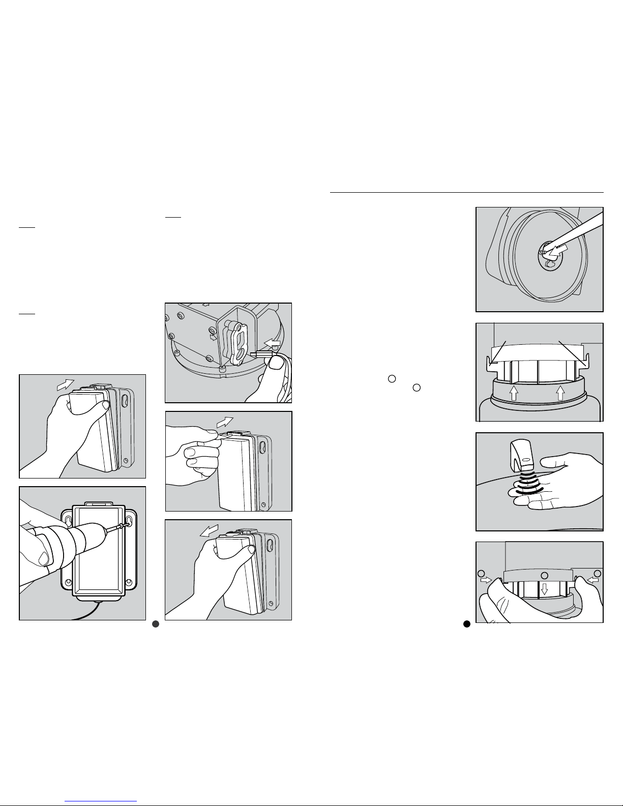
6. Insert the support shaft thru the hole in
the countertop (see gure 5).
7. Rotate the support shaft so the arrow
points toward the sink (see gure 6).
8. Remove the adhesive liner from the
plastic support ring and from the
underside of the countertop, slide it
thru the support shaft and push it until
up until it sticks to the underside of the
countertop (see gure 7).
Note: If the support ring will not sit flush
with the underside of the countertop
due to interference with the sink, use
the optional split support ring provided
instead.
9. Break away the center portion of the
plastic template and discard the piece
removed (see gure 8).
10. Place the plastic template over the
support shaft. Rotate the support shaft
until the exact location of the soap
discharge head is reached. Remove the
template and discard (see gure 9).
11. IMPORTANT – Using a Phillips bit in a
power driver, tighten at full speed the
2 screws on the support shaft until the
plastic heads
break away
. Remove the
remains of the white plastic heads from
the support shaft (see gure 10).
Fig. 1
10:00
Faucet
2:00
Ideal Dispensing
Head Placement
Optional Area
of Installation
Fig. 3
3.5”
Fig. 5
Fig. 9
Fig. 7
Fig. 8
Fig. 6
Fig. 10