1
EN
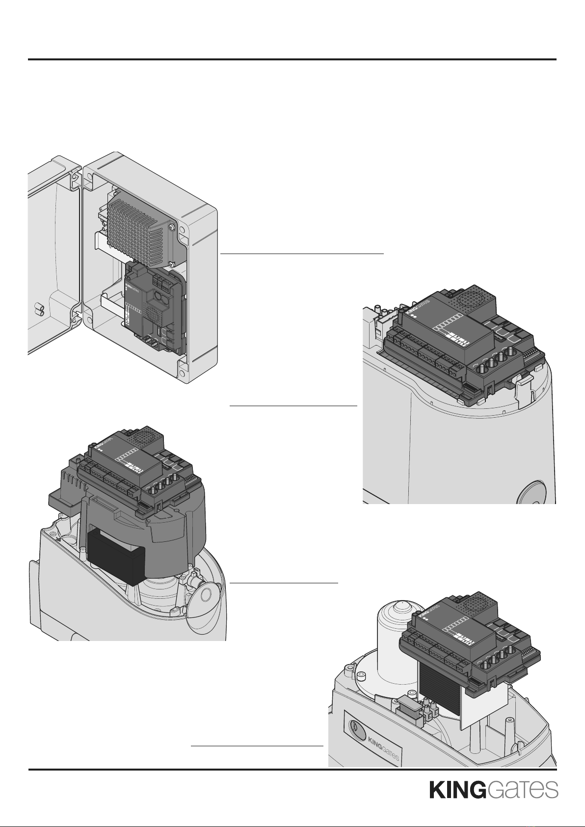
1. Product description
1.1 - Commissioning
To start-up the system, the following steps must be carried out:
1 - Check cabling, tighten all connections and terminals. Follow
cabling standards and regulations of the country/region.
2 - Set the dip switches (par. 3.1) and knobs (par. 3.2) according to
-
tion.
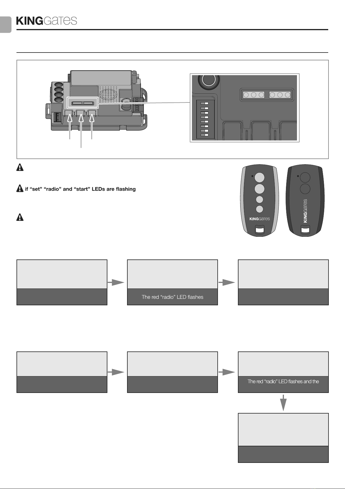
3 - Memorise the transmitters (Paragraph 4).
4 - Programme the gate travel path (Paragraph 5) so that the .
control unit learns the gates open and close points.
5 - Perform the checks described in the “Testing and commissioning”
paragraph (Paragraph 6).
If, after completing these steps, the control unit should
malfunction, consult Paragraph 7, “LEDs indication”, to iden-
tify any issues, and Paragraph 9, “Troubleshooting”, to attempt
to solve it.
1.2 - Main Features
- Flasher control with/without integrated intermittency function (Par-
agraph 9.3).
- Integrated management for electric locks 24V max. 15VA (Para-
graph 9.4).
This output can also be used to control courtesy lights (Paragraph 13).
-
Double NC input for opening and closing limit switch (Paragraph 9.8).
- Inputs for start, stop and pedestrian opening wired commands,
customisable to open, stop and close (Paragraph 9.9).
- Double input for safety devices: “PHO1” during closing and “PHO2”
during closing and/or opening (Paragraph 9.5).
- Possibility of powering 24VDC accessories (Paragraph 9.6).
- Input for gate status pilot light signalling the position of the leaves
(Paragraph 9.7).
- Input for external antenna that can be used for increasing the
range of the transmitters (Paragraph 9.10).
- Staggered closing of gate leaves adjustable through the knob (Par-
agraph 3.2).
- Pause time for automatic re-closing adjustable to between 0 and
180 sec. with knob (Paragraph 3.2).
- Obstacle sensitivity adjustment with knob (Paragraph 3.2).
- Motor force adjustment with knob (Paragraph 3.2).
- Incorporated radio receiver (433.92MHz), compatible with King-
Gates rolling transmitters.
- 6 indication LEDs (Paragraph 7).
- Slow-speed opening and closing (customisable through dedicated
programming).
1.3 - Technical features of the
control unit
Mains power supply* 230 Vac ±10%, 50 - 60 Hz
Motor power supply 24V DC 280W and 10A peak
motor
Warning light power supply 24V max 15W
Gate pilot lamp power supply 24Vdc max 10 W
Accessories’ power supply
(photocells...) 24 Vdc max 10 W
Radio receiver frequency433.920 MHz
Storable remote controls 170
Radio antenna input RG58
Operating temperature -20 ÷ 50 °C
- Automated access command for 1 or 2 24V motors.
fffoooeeepppyyyttteeehhhtttyyyfffiiiccceeepppsssooowwwtttdddnnnaaaeeennnooohhhccctttiiiwwwssspppiiidddfffooonnnoooiiitttaaarrruuugggiiifffnnnoooCCC
eeesssuuunnniiirrroootttooommm