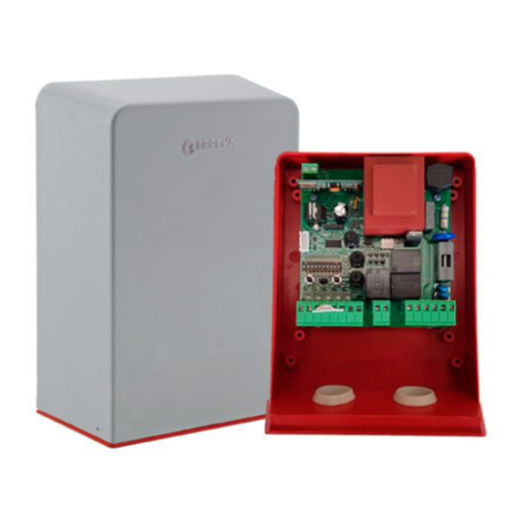
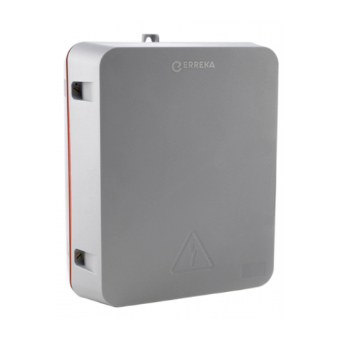
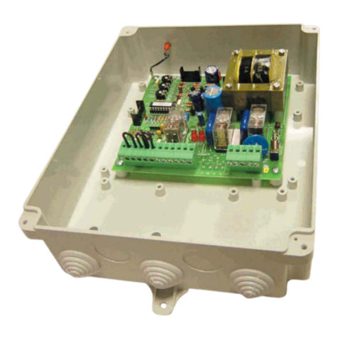
Erreka SMART-D201 Operating instructions

7
SMART-D201(M)
Quick installation and programming guide English
IMPORTANT
NOTE
This quick guide is a summary of the complete installation guide. The guide contains safety warnings and other
explanations that must be taken into account. The most recent versions of this guide and the installation manual
are available at the "Downloads" section on Erreka's website.
http://www.erreka-automation.com
The options and functions described in this guide apply for the firmware version indicated on the circuit. The
firmware, as part of a process of continuous improvement, is subject to new functionalities or upgrades being
included as a result of new versions which are not necessarily compatible with previous ones. For this reason,
some options or functions may differ or be unavailable if your firmware is older than shown in this guide.
E307A
2 x 1mm2
Electrical cables
A: Main power supply
B/F: Flashing light with antenna
C: Photocells (Rx/Tx)
D: Pushbutton/key switch
E:Operator
Elements of the complete installation
NOTE: this control panel is valid for swing
gate operators, for example:
•TEMIS (no encoder or limit switches)
•KAIROS (with or without limit switches)
•ARES 24V
VERY IMPORTANT: the TC closing stopper and
the TA opening stoppers must be installed.
M2-M1-
Lat-
Lit- Lmt4Lmt3
Lmt2
Lit+ SKey
S1
M2+
M1+Lat+ Ph2Ph1 PhVcc PhVcc
S25V
ANT
GND
DKey GND
GND GND GND
Lmt1 GND
J5
J4 J3
J7
J8
COCOCOCO
12345678
9101112131415161718 19 20 21 22 23 24 25 26
LED3
LED4
LED2
FLASH
A.P.
A.T.
EC
(24VDC)
P307Z
DIP1
DEST (LUMI)
FT2
(FT06)
FT1
(FT06)
Peripheral cabling (valid for all cases)
ANT Cable connectors for antenna
EC Electrolock 24 VDC
A.T. Double-leaf opening pushbutton
A.P. Single-leaf opening pushbutton
DEST Flashing light
(ERREKA LUMI)
Configure DIP1 as shown in
figure
FT1 Exterior safety device (ERREKA
FT06 photocell)
FT2 Interior safety device (ERREKA
FT06 photocell)
MSA-114/05 – 2019-09-19 firmware V1.1 or later

8
M2-M1-
Lat-
Lit- Lmt4Lmt3
Lmt2
Lit+ SKey
S1
M2+
M1+Lat+ Ph2Ph1 PhVcc PhVcc
S25V
ANT
GND
DKey GND
GND GND GND
Lmt1 GND
J5
J4 J3
J7
J8
COCOCOCO
1 2 3 4 5 6 7 8
9 10 11 12 13 14 15 16 17 18 19 20 21 22 23 24 25 26
LED3
LED4
LED2
P302W
A1 A2
Operator electrical connections with limit switches (KAIROS)
A1 Operator 1
A2 Operator 2
5/7 M1+ operator 1 /
M2+ operator 2
6/8 M1– operator 1 /
M2– operator 2
For KA3324C only:
13/16 Opening PC A1/A2
14/17 Closing PC A1/A2
15/18 Common PC A1/A2
•Programme F1 for operation with limit
switches for operator KA3324C (F12) or
for operation without encoder or limit
switches for operator KA3324 (F11).
In single-leaf installations,
make the connections in
A1.
M2-M1-
Lat-
Lit- Lmt4Lmt3
Lmt2
Lit+ SKey
S1
M2+
M1+Lat+ Ph2Ph1 PhVcc PhVcc
S25V
ANT
GND
DKey GND
GND GND GND
Lmt1 GND
J5
J4 J3
J7
J8
COCOCOCO
1 2 3 4 5 6 7 8
9 10 11 12 13 14 15 16 17 18 19 20 21 22 23 24 25 26
LED3
LED4
LED2
P303W
A1 A2
+
–
+
–
Operator electrical connections without encoder or limit switches (TEMIS)
A1 Operator 1
A2 Operator 2
5/7 M1+ operator 1 /
M2+ operator 2
6/8 M1– operator 1 /
M2– operator 2
13/16 Opening PC A1/A2
14/17 Closing PC A1/A2
15/18 Common PC A1/A2
•Programme F1 for operation without
encoder or limit switches (F11).
In single-leaf installations,
make the connections in
A1.
+-
J1
DB1
-
+
UP
Trafo
L
N
SMART-D201: 230V/50Hz
SMART-D201M: 125V/60Hz
BAT: 2 x 12V / 1,3 - 15Ah
+
-
P307V
Electricity connection
Battery connection (BAT):
•There is no need to incorporate a charger as
there is already one in the control panel.
•The maximum allowable capacity of the
batteries is 15Ah.
•There is capacity for two batteries of 1.3Ah
maximum inside the box.

9
Display indications, LEDs and pushbuttons
M2-M1-
Lat-
Lit- Lmt4Lmt3
Lmt2
Lit+ SKey
S1
M2+
M1+Lat+ Ph2Ph1 PhVcc PhVcc
S25V
ANT
GND
DKey GND
GND GND GND
Lmt1 GND
+-
J1
Q17
J5
K5
K3
K2K1
J4 J3
J7
F1
DB1
J8
NC NO
CO
+-
NC NO
CO
+--+
CO
NONC
+
CO
NONCNC NO
CO
+-
-
+
12345678
9101112131415161718 19 20 21 22 23 24 25 26
LED3
LED4
LED2
LED Display
LED Azul-Memorización Radio
LED2 Pulsador o Selector de llave
LED3 Fotocélula 1
LED4 Fotocélula 2
UP
SET
DOWN
RF-LEARN
M307C
DL1
DL2
DL4
DL3
Display indications:
Gate open/close not programmed
You have entered open/close programming
Programming open/close about to start
Programming double-leaf gate open/close
Programming single-leaf gate open/close
Programming complete
Memory erased (reset to factory settings)
To return to default settings, hold down "UP" and
"DOWN" until "CLN" appears. The memory
returns to default settings and the display shows
"N-L".
Error in gate operation
The operator has stopped in an intermediate part
of the run
Pushbuttons:
UP Goes through the options during
programming
SET Selects the options during
programming
DOWN Goes back through the options
during programming
RF-LEARN Programmes and erases
transmitters
LEDs:
DL1 (blue) Stores radio code
DL2 Pushbutton or key switch
DL3 FT1 photocell
DL4 FT2 Photocell
Selecting the number of leaves (parameter F1)
1 Hold down "SET" until the display
shows F1. Then release "SET".
2 Press "UP" once: the display
changes to F2.
3 Press "SET" once: the display
changes to F21.
4 Press "UP" once: the display
changes to F22.
5 Press "SET" once: the display
changes to F2.
6 Programming is exited after a few
seconds without pressing any
button.
A307A
A307B

10
Radio code programming (Roller Code transmitters)
1 Connect the power.
Hold down "RF-LEARN" until the
blue DL1 LED lights up.
Release "RF-LEARN" when DL1
comes on.
2 While "DL1" is on, hold the
button for the transmitter to be
programmed down for 5s:
A: Use Channel 1 (button A) for
double-leaf gates
B: Use Channel 2 (button B) for
single-leaf gates
DL1 will flash 3 times to indicate
that programming was correct.
3 Transmitters can be programmed
for as long as DL1 remains on.
DL1 will go off a few seconds after
the last programmed transmitter.
The receiver has memory to store
up to 200 codes.
The radio card receives Standard Roller Code transmitters: IRIS (IR02, IR04) and LIRA (LR02).
It does not receive fixed codes (LUNA/KUMA).
A
B
A
B
R307B
DL1
x3
A
B
5s
5s
R307A
DL1
Deleting all the transmitters
1 Connect the power.
2 Hold down "RF-LEARN" for about 10 seconds, so that
DL1 is turned on and then off. All transmitters are
erased from the memory.
R307F
DL1
Programming open/close
The opening and closing limit switch must be
installed before programming open/close, since
this programming is done with the leaves
travelling as far as they can.
Make sure the F2 parameter (number of operators) is set
correctly: F21 for double-leaf gates; F22 for single-leaf
gates (see section “Selecting the number of leaves
(parameter F1)” on page 9).
Having the F31 parameter programmed is
recommended when programming the TEMIS and
KAIROS operators. F32 is recommended for the ARES
24V.
Open the leaves slightly before programming open/close.
Closing must be the first movement of each leaf when
programming the run (step 3). If this is not the case,
exchange the M+ and M- cables of the associated
motors.
1 Hold "UP" + "SET" + "DOWN"
down at the same time until the
display shows "LEA". Then release
the three buttons.
2 The double-leaf gate's open/close
is programmed by pressing the
transmitter's A button until the
display shows “ARN”.
The single-leaf gate's open/close is
programmed by pressing the
transmitter's B button until it
shows “ARN”.
3 Wait while the leaf runs are
carried out and programmed: The
display shows "LEA" + "D-G" in
double-leaf gates, and "LEA" +
"S-G" in single-leaf gates.
The display will show "RUN"
when programming finishes.
A
B
A
B
A
B
A
B
A
B
A
B
G307A
11
INITIAL NOTES:
F3 menu, trapping force: this parameter must be set to value F31 (for TEMIS and KAIROS operators) or value F32 (for ARES
24V) when programming open/close. After programming open/close, the display shows a figure indicating the current value
multiplied x 10 (showing 10 for 1A, 20 for 2A, etc).
F9 menu: the exterior photocell (FT1) only works during closing.
The interior photocell (FT2) works both during opening and closing.
The voltage output for the 24 VDC flashing light is intermittent (FB menu).
The flashing light used should therefore be configured in static mode.
Change the FC0 parameter to FC1 to enable the exterior safety photocells (FT1).
Change the FD0 parameter to FD1 to enable the interior safety photocells (FT2).
Menu Description Options
Preset
option
Options or values
F1 Encoder / Limit switches F11 F11 F11: not installed
F12 F12: with limit switches
F13 F13: with single encoder
F2 Number of operators F21 F21 F21: two operators
F22 F22: one operator
F3 Maximum trapping current:
Select F31 while programming
TEMIS and KAIROS.
Select F32 while programming
ARES 24V.
F31 F31 F31: 2A
F32 F32: 3A
F33 F33: 4A
F34 F34: 5A
F4 Gate speed F41 F41 F41: 100% of maximum speed
F42 F42: 80% of maximum speed
F5 Slowdown F51 F51 F51: slowdown in opening and closing
F52 F52: no slowdown
F6 Slowdown speed F61 F62 F61: 70% of maximum speed
F62 F62: 50% of maximum speed
F63 F63: 35% of maximum speed
F64 F64: 25% of maximum speed
F7 Lapse between leaves in
opening and closing
F71 F71 F71: 2 seconds
F72 F72: 3 seconds
F73 F73: 4 seconds
F74 F74: 5 seconds
F75 F75: 6 seconds
F76 F76: 7 seconds
F77 F77: 8 seconds
F78 F78: 9 seconds
F79 F79: 10 seconds
F8 Automatic or step-by-step
operation mode and standby
time (in seconds) in automatic
mode
F80 F80 F80: Step-by-step mode
F81 F81: Automatic mode and stand-by time 3s
F82 F82: Automatic mode and stand-by time 10s
F83 F83: Automatic mode and stand-by time 20s
F84 F84: Automatic mode and stand-by time 40s
F85 F85: Automatic mode and stand-by time 60s
F86 F86: Automatic mode and stand-by time 120s
F87 F87: Automatic mode and stand-by time 180s
F88 F88: Automatic mode and stand-by time 300s
F9 Functions of FT1-FT2 F91 F91 F91: FT1 exterior photocell, FT2 interior photocell
F92 F92: FT1 exterior photocell, FT2 safety strip
F93 F93: FT1 exterior photocell, FT2 opening device
F94 F94: FT1 photocell interlock, FT2 interior photocell
Complete programming chart

12
Menu Description Options
Preset
option
Options or values
FA Selecting pedestrian opening FA0 FA0 FA0: pedestrian opening is not carried out
FA1 FA1: open the single leaf with the transmitter's B
button
FB Flashing light pre-warning FB0 FB0 FB0: no pre-warning; the light comes on and the gate
starts to move at the same time
FB1 FB1: 3 seconds’ notice; the light comes on and the
gate does not start to move until 3 seconds have
elapsed
FC FT1 photocells (exterior) FC0 FC0 FC0: OFF (disabled)
FC1 FC1: ON (enabled)
FD FT2 photocells (interior) FD0 FD0 FD0: OFF (disabled)
FD1 FD1: ON (enabled)
FE Buzzer FE0 FE0 FE0: OFF (disabled)
FE1 FE1: ON (enabled)
FF Reverse impulse for electric lock FF0 FF1 FF0: OFF (disabled)
FF1 FF1: ON (enabled); the gate reverses slightly to help
release the electric lock
FG Transmitter button for
complete run (open - stop -
close - stop)
FG1 FG1 FG1: transmitter button A
FG2 FG2: transmitter button B
FG3 FG3: transmitter button C
FG4 FG4: transmitter button D
FH Transmitter button for
pedestrian mode
FH0 FH2 FH0: OFF (pedestrian opening is not carried out)
FH1 FH1: transmitter button A
FH2 FH2: transmitter button B
FH3 FH3: transmitter button C
FH4 FH4: transmitter button D
FI Transmitter button to enable/
disable automatic closing mode
When the flashing light and
buzzer are active, the
transmitter's button to enable/
disable automatic closing does
not work until the flashing light
or buzzer stop working
FI0 FI0 FI0: no button
FI1 FI1: transmitter button A
FI2 FI2: transmitter button B
FI3 FI3: transmitter button C
FI4 FI4: transmitter button D
Leaf operation
During opening:
The leaves stop if the transmitter button, pushbutton or key
switch are operated during opening. The leaves close if re-
enabled.
During closing:
The leaves stop if the transmitter button, pushbutton or key
switch are operated during closing. The leaves open if re-
enabled.
During opening and closing:
For safety reasons, the leaves stop if they come across any
obstacle during opening or closing.
Other manuals for SMART-D201
2
This manual suits for next models
1
Table of contents
Other Erreka Control Panel manuals

Erreka
Erreka CLEVER01 User guide

Erreka
Erreka CLEVER03 Operating instructions

Erreka
Erreka CLEVER01 User guide

Erreka
Erreka CLEVER02 User guide

Erreka
Erreka VIVO-D203 Operating instructions

Erreka
Erreka VIVO-D201 User guide

Erreka
Erreka ABC2M-009 User guide

Erreka
Erreka VIVO-D102 User guide

Erreka
Erreka EP1-008 User manual

Erreka
Erreka VIVO-M203 User manual