Kinroad XT110-9 User manual

1
Ⅰ.SAFE DRIVE
Rules for Safe Drive
Check must be conducted,before starting the engine,to prevent mishaps and damage to components.
Only the qualified person who has passed the drive examination with a drive license is permitted to drive the
vehicle but not anybody else without a drive license.
Full preoccupation is required during drive, paying attention to the following points to avoid any possible
hurt to you by other motorized vehicles:
Do not drive too close to other vehicles;
Never contend for lane.
Strictly observe the local traffic rules.
As driving at overspeed is the cause of many accidents. Do not drive at a speed that the actual situation does
not permit.
Particular careshould be exercised at the level crossing of roads, entrance and exit of parking lot or on the
automobile lane.
During drive, grasp the left handlebar by the left hand and the throttle twist grip by the right hand,with feet
on the footrests.

2
Protective wear
1.Protective wear such as helmet with protective mask, dustproof glasses and gloves should be worn during
drive for the sake of personal safety.
2.Loose clothes are not suitable for motorcycle drive or ride as they may get caught on the operating lever
,kick ,footrest or wheel, resulting in danger.
Modification of the vehicle
Caution:
Any unauthorized modification of the vehicle or replacement of the original parts can not ensure driving
safety and is illicit. The user must observe the regulations of the traffic conrtol authorities, We are not responsible
for any vehic le with unauthorized modification.

3
Ⅱ.MAIN DATA
Overall length 1975mm Cylinder bore x stroke 52.4×50.0
Overall width 710mm Compression ratio 9.1:1
Overall height 1090mm Output,max 5.0kw/8000r/min
Wheelbase 1240mm Torque,max 6.8N.m/5000r/min
Dead weight 101kg Idling speed
1500r/min
±
100r/min
Payload 104kg
Displacement of cylinder
108ml
Front wheel 2.50-17 Spark plug A7RTC
Rear wheel 2.75-17 Spark plug gap 0.6~0.8mm
Speed,max 75km/h Gap of air valve
Inlake valve:0.05mm
Braking distance
≤
7m(30km/h) Exhaust valve:0.08mm
Climbability ≥18°Ground clearance 130mm
Capacity of gasoline tank
4.5L Ignition means CDI
Transmission ratio
1 st gear 3.273 2nd gear 1.937
3rd gear 1.350 4th gear 1.043
Final reduction 2.643

4
III.PARTS & SUBASSEMBLIES

5

6

7
IV.OPERATION
Fuel Cock
1.Fuel filling
The capacity of the fuel tank is 4.5L.Leadless gasoline of
No.90or above or low-lead gasoline is required for the
motorcycle.To fuel the vehicle,support it by the main stand,
open the lock cover of the fuel tank and fill fuel through the
opening.
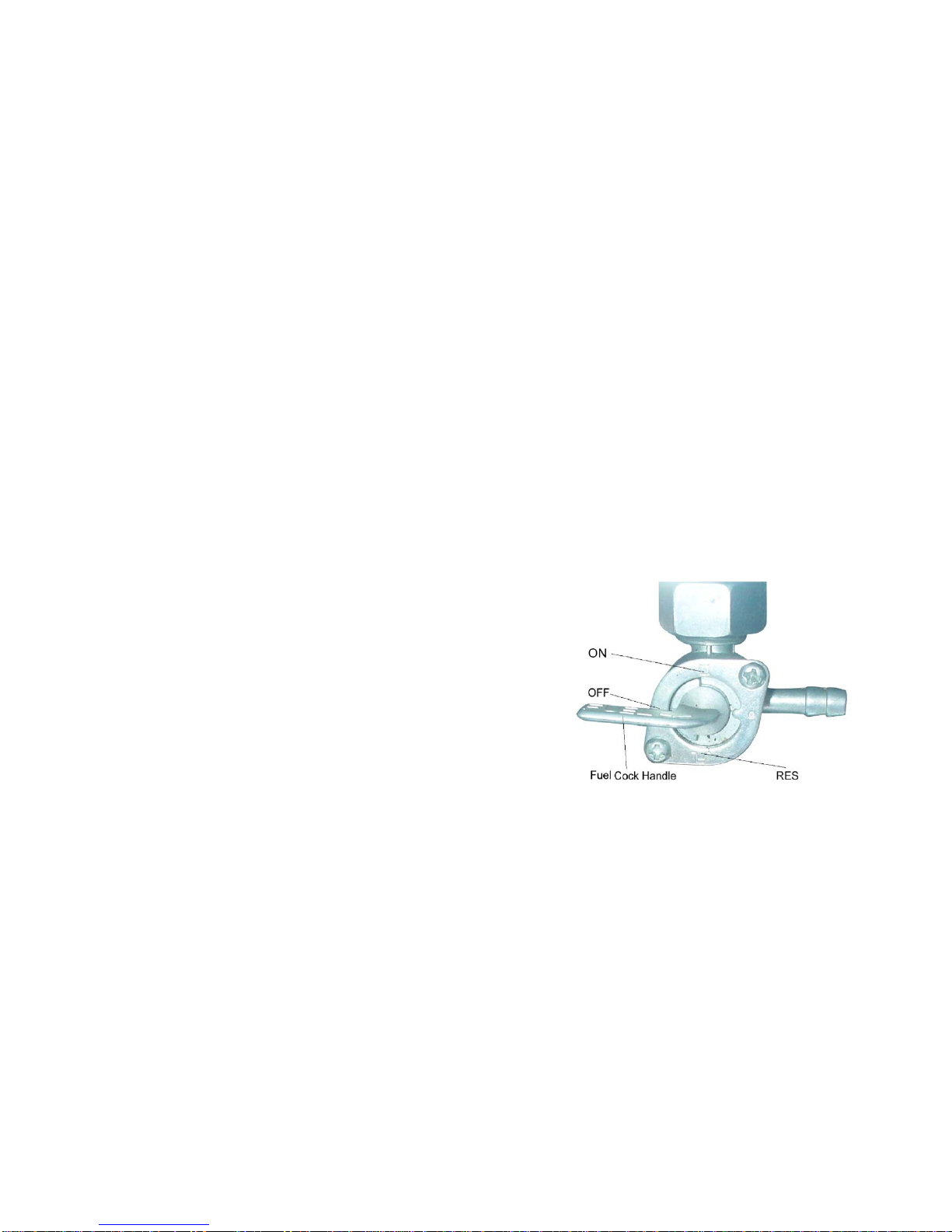
Operation of the fuel cock
ON:With the handle of the fuel cock to
“ON”position,the fuel circuit is through for fuel supply.
OFF:With the handle of the fuel cock fo “OFF”
position,the fuel circuit is cut off without supply.
RES: With the handle of the fuel cock to “RES” position, the
fuel is supplide from the reserve.(Note:The reserved fuel can
only be used when the normal supply is run
out,) In this case,refueling should be carried
out as soon as possible; for there is only
somel.0L of fuel reserve for use.

8
En
g
ine Startin
g
Warnin
g
:Never star
t
the en
g
ine in a closed
p
lace o
r
warehouse o
r
warehouse a
s
the
exhausted
g
a
s
from the vehicle contains toxic
carbon monoxide.
1.Se
t
the ke
y
o
f
the i
g
nition switch to
“ON”
p
osition.
2.Ascertain the neutral
p
osition,where it
should
b
edis
p
la
y
ed.
3.Ascertain the amount o
f
fuel in the tank,
4.Se
t
the fuel coc
k
handle to “ON”
p
osition.
★T
o
star
t
acolden
g
ine;
1.Pull u
p
the choke
b
a
r
o
f
the carburetor
(
to
close the choke
)
.
2.Rotate the throttle twist
g
ri
p
by
1/8to
1/4turn.
3.Start the en
g
ine
by
the electric o
r
the kick
startin
g
s
y
stem.
4.Sli
g
htl
y
turn the throttle twist
g
ri
p
to
increase the s
p
ee
d
o
f
the en
g
ine so a
s
to
war
m
u
p
the en
g
ine.
5.Turn the carbureto
r
choke
b
a
r
downward
to full
y
o
p
en the choke whe
n
the en
g
ine is
sufficientl
y
warme
d
u
p
.
★Caution:
The engine can only be started after the
neutral position is ascertained.Otherwise
accident will happen.
Unnecessary idle running(especially at a
high speed) is harmful to the engine.
★Procedures for stopping the engine:
1.Release the throttle twist grip to slow
down the engine.
2.Turn to the neutral position.
3.Se
t
the i
g
nition switch ke
y
to
“OFF”
p
osition.
4.Set the fuel cockhandle to “OFF”
position.
Switches on Ri
g
ht Handle bar

9
Electric start button
The electric start button is located below the right
handlebar.When the ignition switch is set in “ON” position and the
engine is in the neutral position, push the button to start the engine
by holding the front brake or stepping on the rear brake.
Otherwise,the engine can not be started.
Light switch
The front light switch has three positions,
And “●”(a white point).
When the switch is in this position,the front head
light ,tail and meter lights are all lit up.
When the switch is in this position,the tail, betraying
and meter Iights arelit up.
“●”When it is in this position. The front illuminator, tail,
betraying and meter lights are all off.

10
Switches on LeftHandle bar
1. Headlights dimmer button
Position,Headligh is in high beam.
Position, Headligt is in low beam
2. turning light switch
position,Left
pos ition,Right
3. Horn button
press this button for horn

11
Gear Shifting
A non-c
y
clin
g
mode o
f
g
ea
r
shiftin
g
is em
p
lo
y
ed o
f
this
motorc
y
cle
●The throttle must
b
e closse
d
b
efo
r
the
g
ea
r
shiftin
g
ever
y
time, Shifin
g
the
g
ea
r
b
efore closin
g
the condition o
f
b
ackin
g
it
fo
r
fou
r
times.
●The s
p
ee
d
shiftin
g
p
edal must
b
eo
p
erate
d
suitabl
y
.
●Ste
pp
in
g
on the
g
ea
r
shiftin
g
p
edal is forbided whe
n
drivin
g
to
p
revent dama
g
in
g
the clutch whe
n
chan
g
in
g
the
g
ea
r
abru
p
tl
y
.
N
OTE
(
1
)
N
eutral
g
ea
r
(
N
)
1th
g
ea
r
(
2
)
2nd
g
ea
r
(
3
)
3rd
g
ea
r
(
4
)
4th
g
ea
r
Points for Attention durin
g
Drive
1.Avoid unnecessar
y
idlin
g
o
f
the en
g
ine an
d
it is not allowed. I
n
p
articu lar.to have it id lin
g
a
t
ahi
g
hs
p
eed.
Othe
r
wise it will dama
g
ecom
p
onents seriousl
y
.
2.Shif
t
to the low s
p
ee
d
g
ea
r
whe
n
feeliin
g
tha
t
the
p
owe
r
is not stron
g
enoush on climbin
g
.
3.I
t
is forbidden to us
e
the front
b
rake onl
y
o
r
to coas
t
by
the neutral
g
ea
r
es
p
eciall
y
whe
n
descendin
g
o
r
drivin
g
a
t
hi
g
hs
p
eed.
4.On braking. Narrow the throttle. and then apply the brake

12
V.Checkin
g
,Ad
j
ustm
-
ent and Maintenance
M
ac
hi
ne
Oil
Ch
ec
ki
n
g
★The vehicle should be checked
for machine oil before drive by sup-
porting it with the
Main stand on a flat ground.The oil
livel should be between the upper and
lower
Lines of the oil gauge. Which is not
screwedinto the filling orifice.
★High quality 4-stroke machine
oil. Class SE or SD in API classifi-
cation.of SAE15W-40 in viscosity will
help maintain a long service life or the
engine.In case those are not available,a
substitute suitable for the ambient
temperature of application should be
selected according to the table on the
right side.
R
enewa
l
o
f
M
ac
hi
ne
Oil
Machine oil
p
la
y
saver
y
im
p
ortant
role in the normal o
p
eration o
f
the
en
g
ine an
d
fo
r
this reason,it is necessar
y
to chec
k
the motorc
y
cle fo
r
machine oil
p
eriodicall
y
an
d
renew the oil once
ever
y
800-1,000km o
f
drivin
g
by
the
followin
g
p
rocedures.
Remove the screw
p
lu
g
from the
b
ottom o
f
the hot en
g
ine to drain of
f
all
old oil.
Was
h
the oil filter scree
n
clea
n
an
d
remountitreall
y
to
p
osition.Then fill in
0.8L fres
h
machine oil an
d
star
t
the
en
g
ine fo
r
idle runnin
g
2-3 minutes.
Le
t
the en
g
ine sto
p
fo
r
1-2 minutes
an
d
chec
k
to see whethe
r
the oil level is
in
b
etwee
n
the u
pp
er an
d
lower line
s
o
f
the oil
g
au
g
e.
Do not us
e
an
y
machine oil o
f
a
differen
t
g
rade than the s
p
ecifie
d
one to
avoid machiner
y
failure.

13
Cl
ean
i
ng o
f
mac
hi
ne o
il
t
an
k
Check-up o
f
Spark Plug.
1.Drain off all the run –in machine oil from
the oil tank.
2.Dismount the related parts.
3.Wash clean allthe related parts.
4.Fill in the required oil.
*This job should not be done by untrained
persons but shall be done at an authorized service
center.
1.Remove the cap of spark plug and screw off
the spark plug by the plug wrench.
2.Clean the spark plug all aroud or replace it
if it is corroded or there is too much deposit on it.
3.Regulate the gap of the spark plug to 0.6-
0.7mm.
4.The spark plug of the designated type
should be used. The applicable type of spark plug:
NHSP LDA7RTC made in China.

14
Check-up & Cleaning ofAir Filter
Take out the air filter and check if it is contaminated.
Dismounting:
Remove the right side cover,take out the screw and disassemble the air filter.
Cleaning:
Washthe filter in clean washing oil andwipe it dry with dry cloth.
Soak it in clean machine oil,squeeze it dry and fit it back to position.
Recommended oil:15W/40QE
Caution:
The air filter element for use must be intact or the enine will suck in dust and dirt, resulting in a shorter service
life of the engine.
Water should be prevented from entering into the filter in washing the vehicle.
The filter shall neve
r
b
e cleane
d
with
g
asoline o
r
an
y
othe
r
a
g
en
t
o
f
alow i
g
nition
p
oint.

15
Adjustmen
t
o
f
Throttle Cable
Make sure that the adjusting nut of the throttle
cable and locking nut work normally.
Check to see if the throttle twist grip is with the
required free operating movement.
The required free operating movement:2-6mm.
If the grip can not be so moved freely.turn the
adjust ing nut to ensure it.
After adjustment, start the engine and check for
the free operating movenent again,Repeat the
adjustment if necessary until it is as required.
Adjustmen
t
o
f
Carburetor
Caution:
The adjusting procedures of idling speed:
1.Support the vehicle by a stand.
2.Adjust the idling speed by the throttle stop
screw(1) to 1500±150rpm.
Caution:
Do not try to cover up any trouble of other parts of the
carburetor by adjusting the idling speed. In case of
any abnormality with the carburetor,it has to removed
by your dealer.
Adjustment of idling speed shall be made only when
the cold engine is warmed up or 10 minutes after the
motorcycle is stopped from driving.

16
Check-up & Adjustmen
t
o
f
Air Valv
e
Gap
Noise will stem from too big gap of the air valve. However if there is too small gap or even no gap at all,
closing of the valve will be hindered, which will cause burn of the valve and output drop. Therefore, the air valve gap
must be checkedperiodically.
The gap of the air valve should be inspected and adjusted with a cold engine by the follow ing procedures:
1.Remove the caps of the central hole and the top hole (the ignition timing observation hole)in the left crankcase
cover.
2.Remove the caps of the two air valves on the cylinder head.
3.Insert the “T” key into the central hole of the crankcase cover, jam it against the nut of the flying wheel and
then turm the flying wheel clockwise nutil the engraved “T” mark on the flying wheel alin\gns with the engraved line
on the top of the crankcase cover.Swing the rocking arm slightly.A loose rocking arm(which indicates the existence
of clearance) shows that the piston is in the upper stop position of the compressing t\stroke, where the valve can be
adjusted. A tight rocking arm means thar the piston is in the lower stop position of the compressing stroke, In this
case, continuously turn the “T” key clock wise for 360 degrees until the alignment of those engravd marks, where the
valve can be adjustd,Afterwards,check the valve gap by inserting a feeler in between the valve adjusting screw and
the end of the valve.
The specified air valve gap :0.05mm for the intake and exhaust valves respecively.
Brake Checking
(1) pull up the front andrearbrakes respectively and check for wear of the brake shoes. If the mark “△”onthe
brake drum cover aligns with that “△” on the brake cam, it means that the brake shoes are already worn to the limit
and have to be replaced.
(2) Replacement should be carried out at a designated service center and it is recommended that the parts made
by our company areused therein.

17
Adjustmen
t
o
f
Fron
t
Brake
(1) The front brake has a free operating
movement of 10-20mm as shown in the figure on the
right side.
(2) inspect the reseivoir capacity and refill if
necessary in order to maintain proper level in the
reservior.This should be the major project of your
regular inspection
(3) check the front brake lining for its worm
depth.if its worn depth is up to the limited mark,
replace the brake lining.if the lining doesn’t have
limited mark but a concave slot as the figure,replace
the lining while its worn depth up to the bottom of
concave slot.replacement of a pair of linings shall be
conducted sumultaneously despite only one of them is
worn.

18
Adjustment o
f
Rea
r
Brake
★The vehicle should be supported
by the main stand for check.
(1) The rear brake pedal has a
free operating movement of 20-
30mm as shown in the figure on the
right side.
(2) To make adjustment, turn the
rear brake adjusting nut clockwise
to reduce snd counter clock wise to
increase the free operating
movement of the brake pedal.
Adjustment of Chain
1.When regulation is needed.
Ioosen the rearaxle nut
2.Turn the chail adjusting nuts
on the left and right sides to adjust
the tension of the chain and to align
the marking of the chain adjuster
with the engraved lines in the
similar position, on both sides.
3.Tighten the lock nut and rear
axke nut by a torque of 35-50Nm.
4. Repetitively check the
tension of the chain.
5.When the rear wheel is
changed in position and the chain
adjusted, the free operating
movement of the rear brake pedal
will be affected, which, therefore,
should be checked thereafter and
also regulatedif necessary

19
[Greasing procedures to the driving chain]
1.Shut off the engine.
2.Add some machine oil or chain grease to the driving chain.
Attention:
When the rear wheel axil has moved to the back adjusting limit, if excess loose be cause of wearing to the
driving chain, please change with a new one.

20
Vehicl
e
Washing
Cleaning the vehicle reularly can slow down the color fading of its body and make it easier to check if there is
any damage and oil leakage with if.
Caution:
Washing the motorcycle with over-pressurized water may cause damage to some of its components. Therefore,
do not jet over-pressurized water directly on to the follow ing parts:
——Wheel hub
—— Exhaust pipe
——Fuel tank and lower portion of cushion
——Carburetor
——Head lock and ignition switch
——Meters
(1) After pre-wiping ,the vehicle should be washed with clean water to remove dirty residues so as to prevent
corrosion. Plastic subassemblies should be cleaned by wiping with cloth or foam soaked in neutral detergent solution,
followed by washing with cleanwater.
(2) After the cleanedvehicle is air dried, greasethe chain andrun the engine at idling speedfor afewminutes.
(3) Prior to driving, carefully check the braking system repeatedly and repair or adjust it if necessary.
Table of contents
Other Kinroad Scooter manuals