Klauke TEXTRON EK 22 plus User manual

JCS H:\DOKU\BED_KL\HYDR\HE4872_K.doc
HE.4872_K ©5/98 Anzahl der Seiten: 27
Bedienungsanleitung
Instruction Manual
Handleiding
Käyttöohjekirja
Mode d’emploi
Manual de instrucciones
EK 22 plus, EK22plusINS
Serialnummer

Bedienungsanleitung EK22plus Seite 2
____________________________________________________________________________________________________________________
Bild/Picture 1
8
10
4
5
3
6
1
2
10
9
7
First crimp
Side a
First crimp
Side b
Crimping direction
First crimp
Crimping direction
Side a
Crimping direction
Side b
Bild/Picture 4
Bild/Picture 3
Bild/Picture 2

Bedienungsanleitung EK22plus Seite 3
____________________________________________________________________________________________________________________
Bild/Picture 5-7
Bild/Picture 8
Bild/Picture 9-13
230V/50Hz

Bedienungsanleitung EK 22 plus Seite 4
______________________________________________________________________________________________________________________
Bedienungsanleitung
für das elektro-hydraulische Preßgerät Typ EK 22 plus, EK22plusINS
Seriennummer .........................
Inhaltsangabe
1 Einleitung
2 Aufschriften
3 Gewährleistung
4 Beschreibung des elektro-hydraulischen Preßgerätes
4.1 Beschreibung der Komponenten
4.2 Kurzbeschreibung der wesentlichen Leistungsmerkmale des
Gerätes
4.3 Beschreibung der Leuchtdiodenanzeige
5 Hinweise zum bestimmungsgemäßen Gebrauch
5.1 Bedienung des Gerätes
5.2 Erläuterung des Anwendungsbereiches
5.3 Verarbeitungshinweise
5.4 Wartungshinweise
5.5 Hinweis zur Verwendung des Akkus und des Ladegeräts
5.6 Aufbewahrung und Transport des Preßgerätes
6 Verhalten bei Störungen am Preßgerät
7 Außerbetriebnahme/Entsorgung
8Technische Daten
Symbole
Sicherheitstechnische Hinweise
Bitte unbedingt beachten, um Personen-
und Umweltschäden zu vermeiden.
Anwendungstechnische Hinweise
Bitte unbedingt beachten, um Schäden am
Gerät zu vermeiden.
1. Einleitung
Vor Inbetriebnahme Ihres Preßgerätes
lesen Sie sich die Bedienungsanleitung
sorgfältig durch.
Benutzen Sie dieses Gerät ausschließlich für den
bestimmungsgemäßen Gebrauch.
Das Preßgerät darf nur durch eine elektrotechnisch unterwiesene
Person bedient werden. Das Mindestalter beträgt 16 Jahre.
Diese Bedienungsanleitung ist während der gesamten Lebensdauer
des Gerätes mitzuführen.
Der Betreiber muß
- dem Bediener die Betriebsanleitung zugänglich machen und
- sich vergewissern, daß der Bediener sie gelesen und verstanden
hat.
2. Aufschriften
Auf dem an dem Gehäuse angebrachten Typenschild finden Sie
Typbezeichnung, Herkunftsangabe und den Firmennamen. Auf der
gegenüberliegenden Seite des Gehäuses befindet sich ein
Aufkleber mit einer Kurzdarstellung der preßbaren Querschnitte
für Kupfer und Aluminium und der Preßkraft. Die Seriennummer
befindet sich auf dem Hydraulikzylinder zwischen Gehäuse und
Preßkopf. Am Preßkopf befindet sich ein Hinweis auf eine
mögliche Quetschgefahr bei Preßvorgängen.
3. Gewährleistung
Die Gewährleistung beträgt bei sachgemäßer Bedienung und unter
Einhaltung der vorgeschriebenen Serviceintervalle 6 Monate ab
Lieferdatum, sofern keine gesetzlichen Bestimmungen davon
abweichende Gewährleistungen fordern.
4. Beschreibung des elektro-hydraulischen Preßgerätes
4.1. Beschreibung der Komponenten
Das elektro-hydraulische Preßgerät mit unserer Typbezeichnung
EK 22 plus ist ein handgeführtes Gerät und besteht aus folgenden
Komponenten:
Tabelle 1 (siehe Bild 1 Seite 2)
Pos.-
Nr. Bezeichnung Funktion
1 Bedienungs-
schalter
Auslösung des Preßvorgangs
2 Rückstelltaste Taste zum Öffnen der Preßeinsätze im
Fehler-, bzw. Notfall
3 Zuganker Vorrichtung zum Öffnen des Preßkopfes
4 Druckknöpfe Vorrichtung zum Entriegeln der
Preßeinsätze
5 Gehäuse Ergonomisch geformtes Kunststoff-
gehäuse
6 Leuchtdioden-
anzeige
Kontrollinstrument zum Feststellen des
Ladezustandes, eines Geräte-fehlers und
zur Wartungsanzeige.
7 Akku wiederaufladbarer 3Ah NiMH Akku
(RA5)
8 Ring Öse zur Sicherung des Gerätes und/oder
zu Montagezwecken
9 Handschutz Bügel zum Schutz der bedienenden Hand,
kein Transportgriff!
10 Preßeinsätze Halbschalen Werkzeugeinsätze mit
unterschiedlichen Preßprofilen
4.2 Kurzbeschreibung der wesentlichen Leistungsmerkmale des Gerätes
-Das Gerät besitzt einen automatischen Rücklauf, der den Kolben nach
Erreichen des max. Betriebsüberdruckes automatisch in die
Ausgangslage zurückfährt.
-Das Gerät ist mit einem Nachlaufstop ausgerüstet, der den Vorschub
nach Loslassen des Bedienungsschalters (Pos.-Nr. 1) sofort stoppt.
-Das Gerät ist mit einer Doppelkolbenpumpe ausgestattet, die durch
einen schnellen Vorschub und einen langsamen Arbeitshub
gekennzeichnet ist.
-Der Preßkopf ist stufenlos 360° um die Längsachse drehbar. Dieses
ermöglicht Montagen auch an sehr schlecht zugänglichen Stellen.
-Die EK 22 plus ist mit einer Mikroprozessor-Steuerung ausgestattet,
die den Motor nach vollendetem Preßvorgang abschaltet, Service
Intervalle anzeigt, den Ladezustand des Akkus (Pos.-Nr. 7) angibt und
eine Fehlerdiagnose durchführt.
4.3 Beschreibung der Leuchtdiodenanzeige
Die Leuchtdiode (Pos.-Nr. 6) dient in Verbindung mit der Steuerungs-
elektronik zur Information über den Zustand des Akkus (Pos.-Nr. 7) und
des Werkzeuges. Im einzelnen leuchtet die Diode in folgenden Fällen:
Signal Dauer Zeitpunkt Bedeutung
wenige Sekunden
Blinken
beim Einsetzen des
Akkus
Durchführung
des Selbsttests
20 Sekunden
Dauerleuchten
Nach dem
Arbeitsvorgang
Akku leer
1
20 Sekunden
Blinken (2Hz)
Nach dem
Arbeitsvorgang
Fehler oder
Wartung fällig
2
20 Sekunden
Blinken (5Hz)
Während der Dauer
der Übertemperatur
Gerät zu heiß
20 Sekunden
Leuchten und
Blinken
Nach dem
Arbeitsvorgang
Wartung fällig
und Akku leer
1Anmerkungen:
- Blinkt die Leuchtdiode ab einem bestimmten Zeitpunkt immer am Ende eines
Arbeitsvorgangs für etwa 20 Sekunden, dann ist eine Wartung fällig. Das Gerät ist
baldmöglichst ins Werk einzuschicken.
-Beim Auftreten eines Fehlers blinkt die Leuchtdiode gleichfalls am Ende eines
Arbeitszykluses. Das Blinken zeigt in diesem Fall das Ansprechen der
elektronischen Sicherung an. Eine mögliche Ursache dafür ist der Versuch, einen
Zyklus mit einem unzulässig entleerten Akku durchzuführen. Tritt das Blinken
auch nach Auswechseln des Akkus weiterhin auf, liegt eine andere Störung vor
oder eine Wartung ist fällig. In diesen Fällen ist das Gerät ins Werk einzuschicken.
2Wird das Gerät zu heiß schaltet sich das Gerät selbständig ab. Nach Absinken der
Temperatur ist das Gerät automatisch wieder einsatzbereit.

Bedienungsanleitung EK22plus Seite 5
____________________________________________________________________________________________________________________
5. Hinweise zum bestimmungsgemäßen Gebrauch
Vor Arbeitsbeginn sind alle aktiven, d.h. stromführenden Teile im
Arbeitsumfeld des Monteurs freizuschalten. Ist dieses nicht
möglich sind entsprechende Schutzvorkehrungen2für das Arbeiten
in der Nähe von unter Spannung stehenden Teilen zu treffen. Als
Sonderausführung wird die EK22plus auch als EK22plusINS mit
isolierten Preßkopf angeboten, die besonders für das Arbeiten in
der Nähe von unter Spannung stehenden Kabeln konzipiert ist.
Es sollte vor Arbeitsbeginn der Ladezustand des Akkus (Pos.-Nr.
7) überprüft worden sein3. Ein niedriger Ladezustand kann
beispielsweise an der Leuchtdiode (Pos.-Nr. 6) durch ein 20 s’iges
Aufleuchten am Ende einer Pressung erkannt werden.
Halten Sie Ihren Arbeitsbereich sauber und aufgeräumt.
Verwenden Sie dieses Werkzeug nicht wenn Sie müde sind oder
unter Einfluß von Drogen, Alkohol oder Medikamenten stehen.
5.1. Bedienung des Gerätes
Zuerst erfolgt die Auswahl des geeigneten Preßeinsatz (Pos.-Nr.
10).
Achtung
Preßwerkzeug niemals ohne Preßeinsätze betätigen!
Anschließend wird der Zuganker (Pos.-Nr. 3) ausgerastet (Bild 2
Stellung A) und der Preßkopf geöffnet. Die beiden Hälften der
Preßeinsätze werden nacheinander seitlich unter Betätigung der
Druckknöpfe (Pos. 4) bis zum Einrasten eingeschoben (Bild 2
Stellung E). Nachfolgend wird der Preßkopf wieder vollständig
geschlossen wurde.
Der Presskopf sollte möglichst vor Beginn des Pressvorganges in
die gewünschte Position gedreht werden. Im drucklosen Zustand
lässt sich der Presskopf deutlich leichter drehen.
Die Betätigung des Bedienungsschalters (Pos.-No. 1) leitet den
Preßvorgang ein, der durch das Zusammenfahren der Preßeinsätze
gekennzeichnet wird (Bild 2 Stellung C).
Dabei befindet sich das auf den Leiter aufgeschobene
Verbindungsmaterial bei geschlossenem Preßkopf in dem
Preßprofil der stationären Hälfte des Preßeinsatzes4.
Ein Preßvorgang ist abgeschlossen, wenn die Preßeinsätze (Pos.-
Nr. 10) zusammengefahren sind. Der Rücklauf des Kolbens erfolgt
automatisch nach Erreichen des max. Betriebsüberdruckes.
Anschließend kann ein weiterer Preßvorgang vorgenommen
werden oder durch Öffnen des Zugankers (Pos.-Nr. 3) das
Verbindungsmaterial aus dem Preßkopf herausgenommen werden.
Achtung
Vor Auswechselung der Preßeinsätze
unbedingt Akku gegen unbeabsichtigtes
Betätigen aus dem Gerät entfernen.
Durch Drücken der Rückstelltaste (Pos.-Nr. 2) können im Fehler-,
bzw. Notfall die Preßeinsätze in die Ausgangsposition
zurückgefahren werden (Bild 2 Stellung B).
Achtung
Der Preßvorgang kann jederzeit durch Loslassen
des Betätigungsschalters unterbrochen werden.
5.2. Erläuterung des Anwendungsbereiches
Das Preßgerät verfügt über eine große Anzahl verschiedener
Preßeinsätze (Pos.-Nr. 10) zum Verpressen von Klauke-
Verbindungsmaterial.
2Siehe DIN EN 50110-1
3siehe Kapitel 5.5
4Siehe Bild 4 – Montagehinweis für Kabelschuhe und Verbinder
Tabelle 2 (siehe Bild 3 auf Seite 2)
Kennzeichnung
Preß-
bereich
mm²
Preßeinsätze
außen Preß-
profil
Oberfläche
des Preß-
einsatzes
Preß-
breite
6-300 RKS und VB
Normal-
ausführung
CU, QS QS gelb chro-
matiert
5 mm
6-240 Preß-KS und –
VB
DIN 46235/
DIN 46267
CU, QS,
DIN
46235
Kenn-
zahl
gelb chro-
matiert
5 mm
10-240 Aluminium KS
und VB
AL, QS Kenn-
zahl
blau
verzinkt
7 mm
25-185 Al-Preß-
verbinder
Aldrey
Al, QS Kenn-
zahl
blau
verzinkt
7 mm
Al, QS Kenn-
zahl
blau
verzinkt
7 mm25/4-
120/20
Preßverbinder
DIN 48085 T3
St, QS Kenn-
zahl
brüniert 5 mm
10-240
sm
35-300
se
Runddruck-
einsatz
RU;
QS,sm;
QS,sm
- gelb chro-
matiert
-
10-70 Quetsch-/Stift-
KS
CU, QS,
DIN
46234
QS gelb chro-
matiert
-
10-70 isolierte
Quetsch-KS
ISQ, QS QS gelb chro-
matiert
-
10-70 Rohr-RKS für
fein-drähtige
L.
F, QS QS gelb chro-
matiert
-
4-50 C-Abzweig-
klemmen
C, QS - gelb chro-
matiert
5 mm
10-150 RKS und VB
isoliert,
Stift-KS
isoliert
IS, QS QS gelb chro-
matiert
-
2x50-
2x70
Doppel-Preß-
RKS
DP, QS QS gelb chro-
matiert
5 mm
10-50 Nickel-RKS +
VB
Ni, QS - blau
verzinkt
5 mm
10-70 Ovale Preß-VB Cu o.
Al, QS
QS gelb chro-
matiert
5 mm
10-185 AEH DIN
46228
AE, QS - gelb chro-
matiert
-
2x4-
2x16
Twin AEH AE,
2xQS
- gelb chro-
matiert
-
Abkürzungen: RKS=Rohr Kabelschuhe, VB=Verbinder,
AEH=Aderendhülsen, QS=Querschnitt, L=Leiter
Achtung
Es dürfen nur die in Tab. 2 genannten
Verbindungsmaterialien verpreßt werden.
Sollten andere Verbindungsmaterialien verpreßt werden müssen, ist eine
Rücksprache mit dem Werk zwingend erforderlich.
Achtung
Es dürfen keine unter Spannung stehenden Teile
verpreßt werden. Das Werkzeug gilt nicht als
isoliert.
Bei der EK 22 plus handelt es sich um ein handgeführtes Gerät, das
nicht eingespannt werden darf. Es darf nicht für den stationären Einsatz
verwendet werden. UnterEinhaltung bestimmter Bedingungen kann das
Gerät auch stationär mit unserem Präsentationsständer EKST betrieben
werden. Die Bedingungen entnehmen Sie bitte der Bedienungs-anleitung
des EKST.
Das Gerät ist nicht für den Dauerbetrieb geeignet. Es muß nach ca. 30-
40 Verpressungen hintereinander eine Pause von ca. 15 min eingelegt
werden um das Gerät abzukühlen.
Achtung
Bei zu intensivem Gebrauch kann es durch Erhitzung zu
Schäden am Gerät kommen.

Bedienungsanleitung EK22plus Seite 6
____________________________________________________________________________________________________________________
Achtung
Beim Betrieb von Elektromotoren kann es zur
Funkenbildung kommen, durch die
feuergefährliche oder explosive Stoffe in Brand
gesetzt werden können.
Achtung
Das elektrohydraulische Preßgerät darf nicht bei
starkem Regen oder unter Wasser eingesetzt
werden.
5.3. Verarbeitungshinweise
Bitte beachten Sie unbedingt die im Katalog Kapitel 12
angeführten Montagehinweise5.
Achtung
Es dürfen auch bei gleicher Kennzahl nur die für
das Material vorgesehenen Preßeinsätze verwendet
werden.
5.4. Wartungshinweise
Das Preßgerät ist nach jedem Gebrauch zu reinigen und trocken zu
lagern. Sowohl Akku als auch Ladegerät müssen vor Feuchtigkeit
und vor Fremdkörpern geschützt werden.
Das Gerät ist wartungsfrei, lediglich die Bolzenverbindungen sind
leicht einzuölen.
Im Rahmen des bestimmungsgemäßen Gebrauchs dürfen vom
Kunden nur die Preßeinsätze (Pos.-Nr. 10) gewechselt werden.
Achtung
Geräteversiegelung nicht beschädigen!
Bei Beschädigung der Geräteversiegelung erlischt der
Garantieanspruch.
Lassen Sie Ihr Gerät nur von qualifiziertem Fachpersonal und nur
mit Originalersatzteilen reparieren. Damit wird sichergestellt, dass
die Sicherheit des Gerätes erhalten bleibt.
5.5. Hinweis zur Verwendung des Akkus und des Ladegerätes
Das Ladegerät ist für 230 V/50-60 Hz ausgelegt. Neue Akkus
müssen vor dem erstmaligen Gebrauch geladen werden. Zur
Aufladung des Akkus wird der Stecker des Ladegerätes in die
Steckdose und der Akku in das Ladegerät eingesteckt (Bild 5). Die
Ladezeit beträgt ca. eine Stunde (Bild 6). Der Ladezustand des
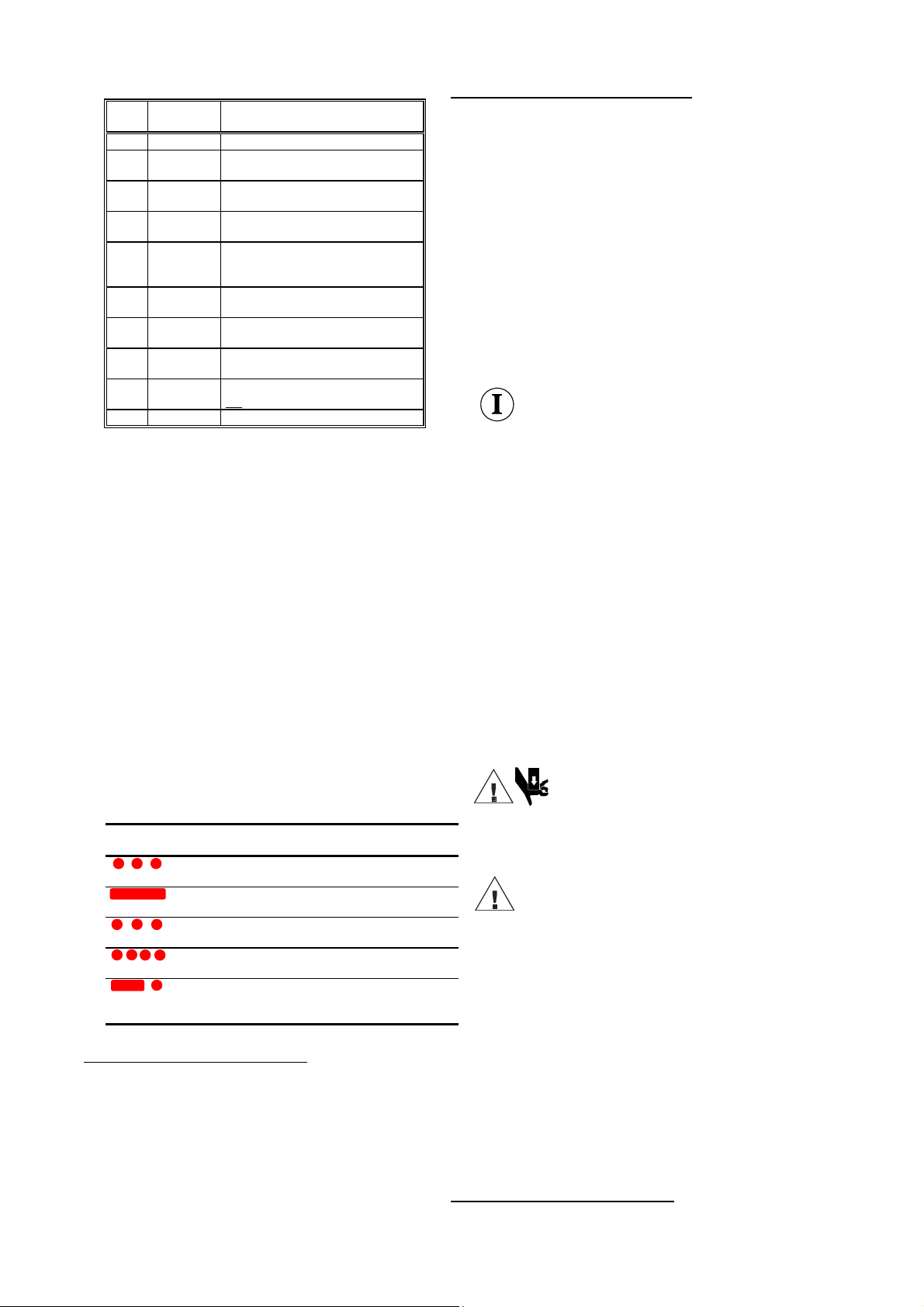
Akkus6wird an der Leuchtdiode am Ladegerät abgelesen.
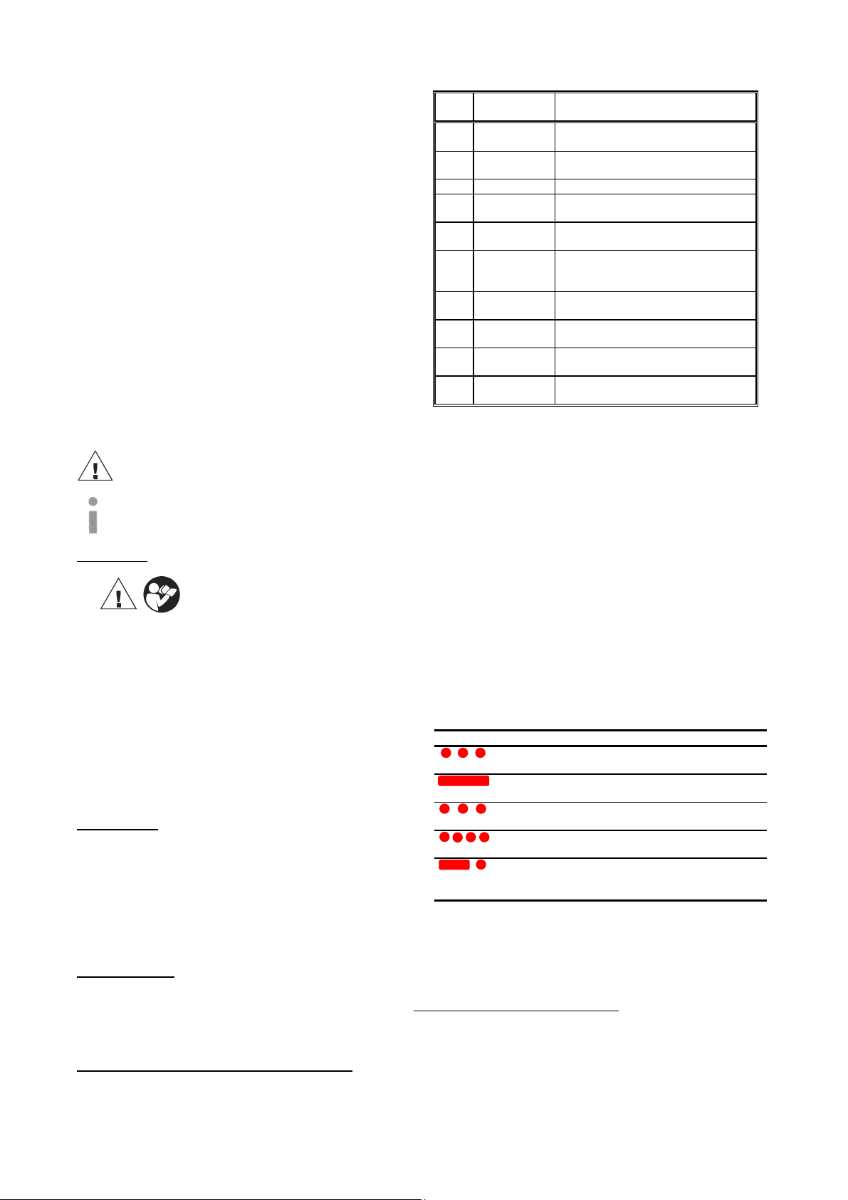
grün: Akku ist aufgeladen
rot: Akku wird gerade geladen.
blinken: Akku nicht vollständig eingeschoben oder Akku
zu heiß, ein akustisches Signal ertönt.
Ist der Ladevorgang abgeschlossen wechselt das Ladelicht wieder
auf grün, wobei gleichzeitig ein akustisches Signal 5 Sekunden
lang ertönt.
Es dürfen keine artfremden Akkus weder in der Presse noch im
Ladegerät verwendet werden.
Laden Sie Ihren Akku auf, sobald die Geschwindigkeit Ihrer
Maschine merklich nachläßt, bzw. die Anzeige am Gerät (siehe
Kap. 4.3) auf einen leeren Akku hinweist. Laden Sie nicht
vorsichtshalber einen teilentladenen Akku nach. (Bild 11)
Wenn Sie einen Akku aus einem kürzlich betriebenen Gerät oder
einen, der längere Zeit in der Sonne lag, laden, kann das
Aufladelicht rot blinken. Warten Sie in diesem Fall eine Weile.
Das Aufladen beginnt nach Abkühlung des Akku.
Wollen Sie zwei Akkus nacheinander aufladen, warten Sie 15 min
bevor Sie den zweiten Akku laden.
5Siehe auch Bild 4 auf Seite 2 dieser Bedienunganleitung
6Der Ladezustand des Akkus kann auch an der LED des Gerätes durch
Leuchten am Ende einer Pressung erkannt werden. Siehe Kap. 4.3.
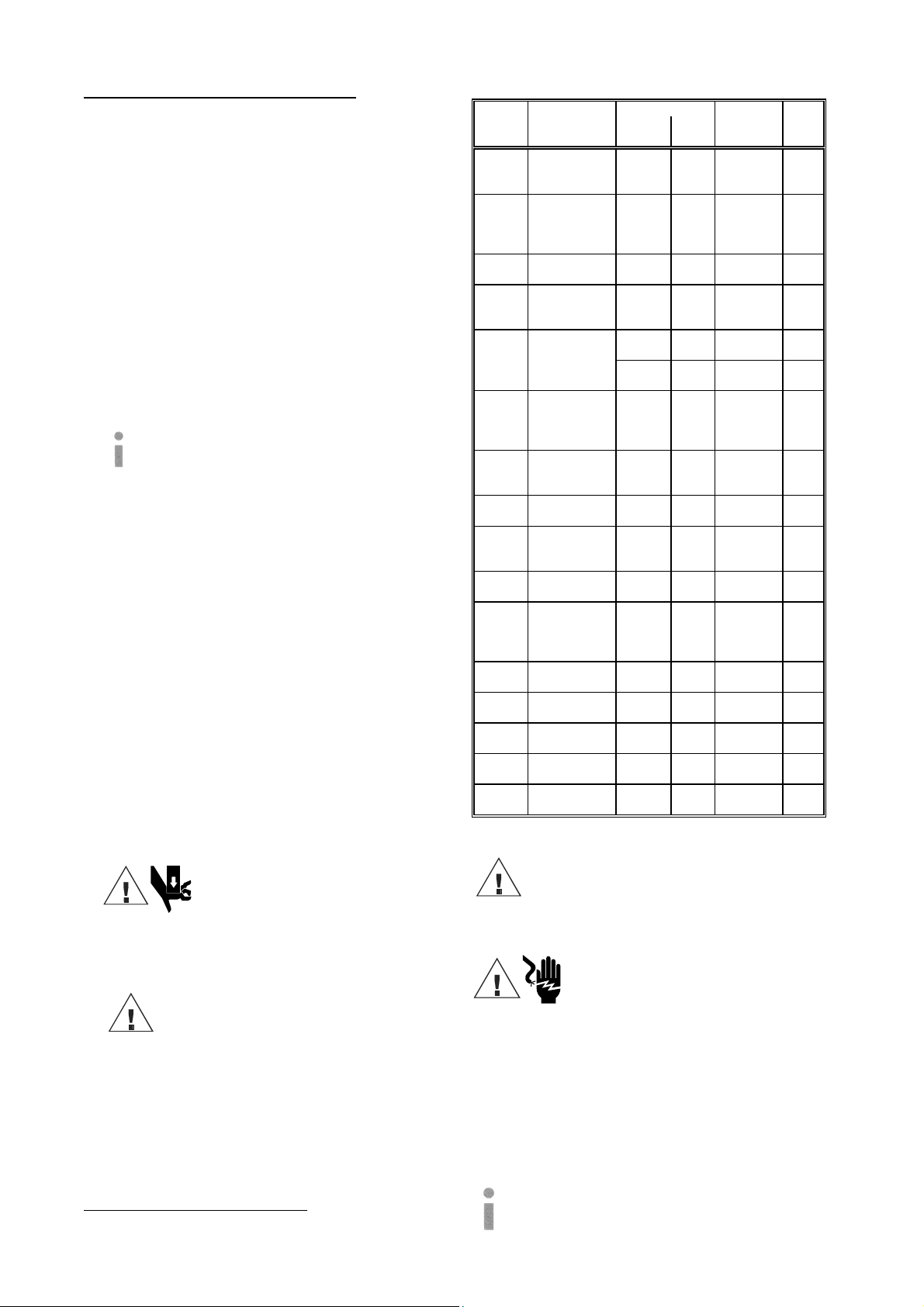
Blinkt das Aufladelicht abwechselnd rot und grün und wird ein
Warnsignal 20 sec. lang abgegeben, ist das Aufladen nicht möglich. Die
Pole des Ladegerätes oder die des Akkus sind durch Staub verschmutzt
oder der Akku ist verbraucht oder beschädigt.
Laden Sie den Akku bei einer Raumtemperatur von 0°C bis 40°C (Bild
8). Lassen Sie das Ladegerät nie im Regen oder Schnee liegen (Bild 10).
Laden Sie den Akku nicht in Anwesenheit leicht entzündbarer Stoffe
oder Gase (Bild 9).
Tragen Sie das Ladegerät nie am Netzkabel und ziehen Sie es nicht
gewaltsam aus der Steckdose heraus. Stecken Sie keine fremden
Gegenstände in die Lüftungsgitter des Ladegerätes (Bild 13).
Das Laden der Akkus darf nur in den vom Hersteller vorgeschriebenen
Ladegeräten vorgenommen werden.
Achtung
Stecken Sie den Akku nicht in Ihre Hosentasche oder in
Ihre Werkzeugkiste, wenn sich in ihnen leitfähige Teile
befinden, wie z.B. Münzen, Schlüssel, Werkzeuge oder
andere metallische Teile.
Ziehen Sie den Stecker des Ladegerätes nach dem Laden aus der
Steckdose heraus (Bild 7). Nehmen Sie das Ladegerät nicht auseinander.
Um die Sicherheit und Zuverlässigkeit des Ladegerätes zu gewähr-
leisten sollten Reparatur, Wartung oder Einstellung durch unser Service-
Center durchgeführt werden.
5.6. Aufbewahrung und Transport des Preßgerätes
Um das Preßgerät vor Beschädigungen zu schützen, muß es nach
Gebrauch und nachdem es gesäubert worden ist, in den Transportkoffer
Art.-Nr. MKE 22 gelegt werden, der dann anschließend sicher zu
verschließen ist.
6. Verhalten bei Störungen am Preßgerät
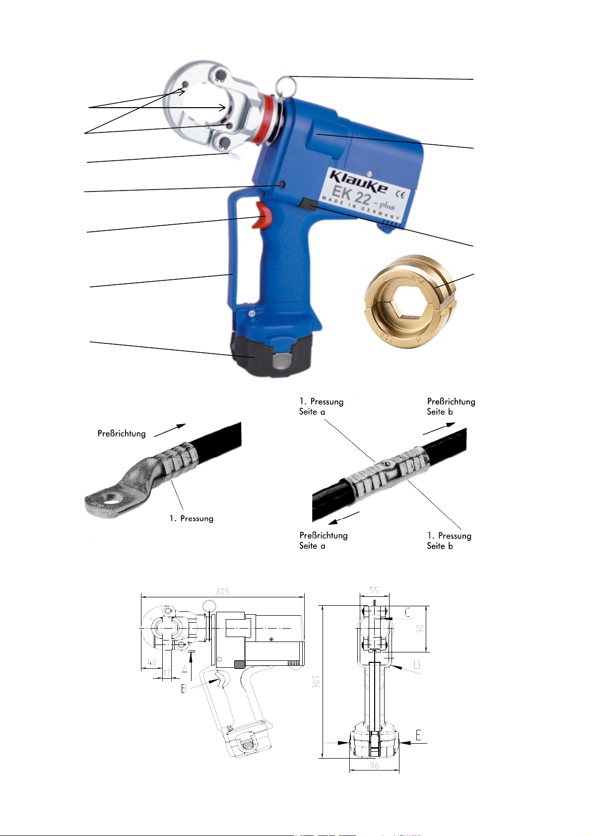
a.) Regelmäßiges Blinken der Leuchtdiodenanzeige (Pos.-Nr. 6)
=> Akku (Pos.-Nr. 7) austauschen. Leuchtet die Anzeige weiter, muß
das Gerät eingeschickt werden. (siehe auch Kap. 4.3)
b.) Das Preßwerkzeug verliert Öl.
=> Das Gerät einschicken. Das Gerät nicht öffnen und die Geräte-
versiegelung nicht entfernen.
c.) Preßwerkzeug erreicht den Enddruck nicht.
=> Preßvorgang unterbrechen. Rückstelltaste (Pos.-Nr. 2) gedrückt
halten und gleichzeitig Bedienungsschalter ca. 10 sec. Dauer-
betätigen. Wird der Fehler dadurch nicht behoben, muß das Gerät ins
Werk eingeschickt werden.
7. Außerbetriebnahme/Entsorgung
Dieses Gerät fällt in den Geltungsbereich der Europäischen WEEE
(2002/96/EG) und RoHS Richtlinien (2002/95/EG), die in Deutschland
durch das Elektro- und Elektronikgerätegesetz (ElektroG) umgesetzt
wurden.
Die WEEE-Richtlinie schreibt die Sammlung und umweltgerechte
Verwertung der Elektro- und Elektronik-Altgeräte vor. Informationen
dazu finden Sie auf unserer Homepage www.klauke.com unter WEEE &
RoHS.
Die RoHS Richtlinie untersagt nach dem 01/07/2006 neue Elektro- und
Elektronikgeräte in Verkehr zu bringen, die mehr als 0,1 Gewichts-
prozent Blei, Quecksilber, sechswertiges Chrom, polybromiertes
Biphenyl (PBB) oder polybromierten Diphenylether (PBDE) oder mehr
als 0,01 Gewichtsprozent Cadmium je homogenem Werkstoff enthalten.
Akku’s (Pos.-Nr. 5) müssen unter Berücksichtigung der Batteriever-
ordung speziell (getrennt) entsorgt werden.
Achtung
Das Gerät darf nicht im Restmüll entsorgt werden. Die
Entsorgung muß durch den Entsorgungspartner der Fa.
Klauke vornehmen werden.
Kontaktadresse: WEEE-Abholung@Klauke.Textron.com

Bedienungsanleitung EK22plus Seite 7
____________________________________________________________________________________________________________________
8. Technische Daten
Gewicht des kompl. Gerätes: ca. 4,15 kg (inklusive Akku)
Preßkraft: ca. 60 kN
Antriebsmotor: Gleichstrom-Permanentfeldmotor
Akkuspannung: 12 V
Akkukapazität: 3 Ah (RA5)
Akku-Ladezeit: ca. 1 h [LG4F], bzw. ¼ h [LG5]
Preßzeit: 3 s bis 6 s (abhängig vom
Verbinderquerschnitt)
Pressungen pro Akku: ca. 170 Pressungen
(Cu 150 mm² DIN 46235)
Hydrauliköl: ca. 65 ml "Shell Tellus T 15"
Umgebungstemperatur: -20°C bis +40°C
Schalldruckpegel: 70 dB (A) in 1m Abstand
Vibrationen: < 2,5 m/s²
(gewichteter Effektivwert der
Beschleunigung)
Maße: Siehe Bild 2
Anmerkung
Diese Bedienungsanleitung kann jederzeit kostenlos unter der
Bestell-Nr. HE.4872_K nachbestellt werden.
Instruction Manual
for the electric-hydraulic crimping unit Type EK 22 Plus,
Serial-No. .........................
Index
1 Introduction
2 Labels
3 Warranty
4 Description of the electric-hydraulic crimping unit
4.1 Description of the components
4.2 Brief description of the important features of the unit
4.3 Description of the light diode display
5 Remarks in respect of the determined use
5.1 Operation of the units
5.2 Explanation of the application range
5.3 Mounting instructions
5.4 Service and Maintenance instructions
5.5 Remarks on the use of the Battery Cartridge and Charger
5.6 Storage and transport of the crimping unit.
6 Troubleshooting
7 Putting out of operation/waste disposal
8 Technical data
Symbols
Safety warnings
Please do not disregard these instructions in order to
avoid human injuries and environmental damages.
Operational warnings
Please do not disregard them to avoid damaging the pump
unit.
1. Introduction
Before starting to use the tool please read the
instruction manual carefully.
Use this tool exclusively for its determined use.
Mounting and assembly of connecting material with the help of this tool
must only be performed by specially trained personnel. The minimum
age is 16 years.
This instruction manual has to be carried along during the entire life
span of that tool.
The operator has
- to guaranty the availability of the instruction manual for the user and
- to make sure, that the user has read and understood the instruction
manual.
2. Labels
On the labels fixed on the housing of the tool you’ll find the type
specification name of the manufacturer and the company logo. On the
opposite side of the housing you’ll find a label with a brief presentation
of the scope of manageable cross-sections for copper and aluminium and
the crimping force. The serial number is on the hydraulic cylinder
between the housing and the crimping head. On the crimping head you’ll
find a warning against possible injuries during the crimping process.
3. Warranty
If correct operation is guaranteed our warranty is 6 months from the time
of delivery unless otherwise specified by local guidelines and law.
4. Description of the electric-hydraulic crimping unit
4.1. Description of the components
The electric-hydraulic crimping unit type EK 22 Plus is a hand held tool
and consists of the following components:

Instruction Manual EK 22 plus page 8
______________________________________________________________________________________________________________________
Table 1 (see Picture 1 page 2)
Pos.-
No. Description Function
1 Trigger switch to start crimping procedure
2 Retract
button
button to open the dies in case of
emergency
3 Latch device to open/close the crimping
head
4 Retaining
clips
button to unlock/remove the dies
5 Housing ergonomically formed plastic housing
for perfect handling with a detachable
lid
6 Light diode
display
indicator for tool functions and battery
charge control
7 Battery
cartridge
rechargeable 3 Ah NiMH battery
(RA5)
8 Ring Loop to secure the tool and/or for
assembly purposes
9 Removable
hand guard
guard to protect the operating hand,
not for transportation
10 Dies interchangeable crimping dies
4.2. Brief description of the important features of the unit
-The hydraulic unit incorporates an automatic retraction which
returns the piston into its starting position when the maximum
operating pressure is reached.
-The unit is equipped with a special brake which stops the
forward motion of the piston/dies when the trigger (Pos.-No. 1)
is released.
-The unit is equipped with a double piston pump which is
characterised by a rapid approach of the dies (Pos.-No. 10)
towards the connector and a slow crimping motion.
-The crimping head can be smoothly turned by 360° around the
longitudinal axis in order to gain better access to tight corners
and other difficult working areas.
-The EK 22 Plus is equipped with a microprocessor which
indicates service intervals, internal checks and low battery
charges. It also shuts off the motor automatically after the crimp
is completed.
4.3. Description of the light diode display
This tool is equipped with a special circuit board incorporating
several important features to inform the user about the current
status of the unit. The diode (Pos.-No. 6) signals in the following
cases:
Signal Duration When it
occures What it means
a few seconds of
flashing
battery
insertion
self check – O.K.
glowing for
20 seconds
after crimp battery discharged
1
flashing for
20 seconds (2Hz)
after crimp return for service
2
flashing for
20 seconds (5Hz)
During high
temperature
unit too hot
20 sec. glowing
and flashing
intermittently
after crimp service required
and battery flat
1Remarks:
-Does the diode signal periodically at the end of a working cycle for
approx. 20 sec the unit must be returned to an authorised Service
Center for Service as soon as possible.
-In case of an error the light diode display also signals periodically at
the end of a working cycle. The signal indicates in this case the
circuit opening by the electronic fuse. A possible reason for that is
that a cycle was performed with an incorrectly low battery. If the
signal occurs even after changing the battery there must be a
different error or a service is due. In these cases the tool must be
returned to the manufacturer or an authorised service center.
2The unit switches off when it gets too hot. It switches on
automatically after the unit cooled off.
5. Remarks in respect of the determined use
Before starting any work on electrical appliances it must be safeguarded
that there are no live parts in the immediate assembly area of the user. Is
this not possible special precaution measures1for working near live parts
must be provided. The EK22plus is also available as an EK22plusINS
with an insulated head which is specially designed for working near live
lines.
Prior to operating the unit the charging level of the battery (Pos.-No. 7)
should have been tested2. A low charging level can be detected by the
flashing of the LED (Pos.-No. 6) for 20 s at the end of a crimping cycle.
Keep your working area clean and tidy. Do not use this tool when you
are tired, on drugs, had alcohol or if you are medicated.
5.1. Operation of the unit
Now you have to select the right dies (Pos.-No. 10) for the intended
application.
Attention
Don’t operate the tool without dies.
The crimping head has to be opened by unhooking the latch (Pos.-No. 3
& Picture 2 Pos. A). Afterwards the retaining clips (Pos.-# 4) have to be
actuated (Picture 2 Pos. E) while the dies will be inserted sideways into
the open crimping head. Afterwards the crimping head must be closed
completely.
The crimping head should be turned into the desired position before
starting the crimping cycle. It is significantly easier to turn the crimping
head in a pressure free state.
The crimping procedure is initiated by actuating the trigger (Pos.-No. 1
& Picture 2 Pos. C). The crimping process is defined by the closing
motion of the dies. During that process the connecting material is
positioned in the stationary half of the die whereas the moving part of
the die is approaching the compression point3.
The crimping process is terminated when the crimping force is reached.
After having completed the crimp the dies return into the starting
position automatically. Afterwards a second crimping cycle can be
initiated or the it can be finished by opening the latch (Pos.-No. 3 &
Picture 2 Pos. A).
Attention
After having terminated the crimping process and
prior to changing the dies remove battery to avoid
unintended starts.
In case of error or emergency the dies can be returned into the starting
position by actuating the retract button (Pos.-No. 2 & Picture 2 Pos. B).
Attention
The crimping process can be interrupted at any moment
by releasing the trigger.
5.2. Explanation of the application range
The EK 22 Plus has a large number of various dies (Pos.-No. 10)
available to crimp Klauke connecting material.
1See EN 50110-1
2See Chapter 5.5 for more information of the battery and charging unit
3See picture 4 page 2

Instruction Manual EK22plus page 9
______________________________________________________________________________________________________________________
Table 2 (see Picture 3, page 2)
Crimping
range
Marking
mm²
Crimping
dies
outside Profile
Surface
of the
dies
crimping
width
6-300 TCL and C.
Standard
Version
CU,
„QS“
„QS“ chrome
plated
5 mm
6-240 TCL and C.
DIN 46235/
DIN 46267
CU,
„QS“,
DIN
46235
code # chrome
plated
5 mm
10-240 Aluminium
CL and C.
AL,
„QS“
code # blue
zinc
7 mm
25-185 Aluminium
C. Aldrey
Al,
„QS“
code # blue
zinc
7 mm
Al,
„QS“
code # blue
zinc
7 mm25/4-
120/20
Full tension
C.
DIN 48085
T3
ST,
„QS“
code # black 5 mm
10-240
sm
35-300
se
Pre-
rounding
dies
RU;
QS, sm;
QS, sm
- chrome
plated
-
10-70 Terminals
DIN 46234
DIN 46230
CU,
„QS“,
DIN
46234
„QS“ chrome
plated
-
10-70 insulated
terminals
ISQ, QS „QS“ chrome
plated,
-
10-70 tub. CL for
fine-str.
conductors
F, QS „QS“ chrome
plated
-
4-50 C-clamps C, QS - chrome
plated
5 mm
10-150 Pre-
insulated
tub. CL and
connectors
IS, QS „QS“ chrome
plated
-
2x50-
2x70
double
compres-
sion CL
DP, QS „QS“ chrome
plated
5 mm
10-50 Ni-CL and
connectors
NI, QS - blue
zinc
5 mm
10-70 Oval
compres-
sion joints
CU or
AL, QS
code # chrome
plated
5 mm
10-185 WF
DIN 46228
AE, QS - chrome
plated
-
2x4-
2x16
Twin WF AE,
2xQS
- chrome
plated
-
Abbreviations: TCL-Tubular cable lugs, C-Connectors,
WF-Wire Ferrules, QS-Cross-section
Attention
Do only crimp those connecting materials
mentioned in Tab. 2
If different conducting materials have to be crimped, please
contact the manufacturer.
Attention
Do not crimp on live cables or conductors!
This is not considered an insulated tool
The EK 22 Plus is a hand held tool and it is not supposed to be
restrained in a vise. It is not allowed to use the tool in a stationary
application. Complying certain conditions the unit can be operated
stationary with our presentation support EKST. The conditions can
be taken from the instruction manual of the EKST.
The tool is not designed for continued crimping operations. After a
sequence of approximately 30-40 completed crimps you have to
make a break of 15 min. to give the tool time to cool down.
Attention
Too intensive use can cause heat damages for the
tool
Attention
During the operation of electric engines sparks can occur
which might ignite highly inflammable or explosive
liquids and materials
Attention
Electric-hydraulic crimping tools should not be operated
in pouring rain or under water.
5.3. Mounting instructions
Please read the assembly instructions in Chapter 12 of our general
catalogue.
Attention
Even if the code number is identical only those dies
should be used whichare suitable for the material.
Please use the following assembly instructions for cable lugs and
connectors:
1. Strip the conductor according to insertion depth (+10% due to the
change of length of the crimped sleeve)
2. The Conductor ends must be cleaned with a cloth or brush before the
assembly.
3. Insert the conductor fully into the cable lug or connector
4. Pay attention to the crimping directions and use the appropriate dies.
The crimping directions3for cable lugs and connectors is indicated in
the illustration below.
5. After crimping, wipe away excess compound forced out of Al-cable
lugs and connectors.
5.4 Service and maintenance instruction
The electric-hydraulic crimping unit is equipped with a controller
enabling the user to see when the next service is due. (Pls. read chapter
4.3 for more information) When the next service is due the unit must to
be returned to an authorised service center.
For every day service the unit has to be cleaned and dried after each use.
The battery cartridge (Pos.-No. 7) and the charging unit have to be
protected against humidity and dust.
Within the determined use of the tool only the dies (Pos.-No. 10) are
permitted to be changed by the customers.
Attention
Do not damage the seals of the tool.
If the seals are damaged the warranty is invalidated.
Have your tool serviced only by qualified service personnel and replace
parts only with genuine spare parts. This will make sure that the safety
standard of the tool will be preserved.
5.5 Remarks on the use of the battery cartridge and charging unit.
The charging unit is run with a nominal voltage of 230 V and a
frequency of 50-60 Hz. New batteries must be charged prior to use. To
charge the battery cartridge (Pos.-No. 7) the power plug of the charging
unit has to be plugged into the power supply and the battery cartridge
has to be pushed into the charging unit (Picture 5). The charging time is
one hour (Picture 6). The charging level of the battery cartridge can be
checked by a LED4.
green battery cartridge is charged
red Battery cartridge is empty and is just being charged
flashing battery cartridge is not pushed in properly or too hot,
a sound signal occurs
Is the battery plugged in correctly the LED changes from green to red
and the charging procedure starts. When the charging procedure is
terminated the LED changes again to green. Simultaneously a signal
occurs for 5 seconds.
No other battery cartridges e.g. dry batteries or car batteries etc. are
permitted to be used neither in the tool nor in the charging unit.
3See Picture 4 on Page 2
4The charging level of the battery can also be verified by the LED of the
tool at the end of a crimping cycle. See chapter 4.3 for further information.

Instruction Manual EK22plus page 10
______________________________________________________________________________________________________________________
As soon as the speed of the machine decreases noticeably the
battery must be recharged. Do not recharge a partially discharged
battery as a precaution (Picture 11).
If charging a battery which has currently been used or which was
laying in the sun for a longer period of time the LED might flash
red. In this case wait for a while. The charging procedure starts
after the battery cooled down.
Does the LED flash red and green and does an audible tone occur
for 20 seconds it is not possible to charge that battery. The poles of
the battery or the charging unit are dirty or the battery is low or
damaged. If you want to charge two batteries in a row wait for 15
min before you charge the second battery.
Avoid great fluctuating temperatures under 0°C and above 40°C
(Picture 8). Through these fluctuations damages may result for the
battery cartridge as well as for the charging unit. The best
operation temperature is between 15-25 °C.
Do not leave or operate the charging unit in rain or snow (Picture
10). Do not charge the battery near lightly inflammable materials
or gases (Picture 9).
Do not use the cord to transport the charging unit or to pull the
plug out of a wall socket with force. Do not insert strange parts
into the ducts of the charging unit (Picture 13).
The charging of the batteries must only be done with charging
units supplied by the manufacturer.
Attention
Do not place the battery in your pocket or in your
toolbox if there are any conductive materials in it
such as coins, keys, tools or other metallic parts.
Pull the plug of the charging unit after charging (Picture 7). Do not
disassemble the charging unit or battery.
In order to safeguard a safe and proper performance of the
charging unit the repair and service of the unit should be made
through our Service Center.
5.6 Storage and transport of the crimping tool
In order to protect the tool against damages it has to be cleaned
carefully after each use and be put into the transportation case Part
No. MKE 22 which has to be closed safely.
6. Troubleshooting
a.) Flashing of the light diode display (Pos.-No. 6)
=> See chapter 4.3 for more information about the special
functions of the tool.
b.) The tool loses oil.
=> Return the tool to the manufacturer. Do not open the tool and
damage the seals of the tool.
c.) The crimping tool does not reach the final operating pressure.
=> Stop the crimping process. Press the retract button (Pos.-No.
2) and the operating switch continuously and simultaneously for
about 10 sec. Is the malfunction not be eliminated by this
attempt the tool has to be returned to the manufacturer.
7. Putting out of operation/waste disposal
This unit is subjected to the scope of the European WEEE
(2002/96/EG) and RoHS (2002/95/EEC) directives.
The WEEE directive regulates the collection and the
environmental friendly recycling of electro and electronic units.
Information about this can be found in our home page
www.Klauke.com under ‘WEEE & RoHS’.
The RoHS directive bans new electrical and electronic equipment
put on the market which contains more than 0,1 weight percentage
lead, mercury, hexavalent chromium, polybrominated biphenyls
(PBB) or polybrominated diphenyl ethers (PBDE) and 0,01 weight
percentage cadmium per homogeneous material.
Battery cartridges (Pos.-No. 7) must be specially disposed of
according to the EEC Battery Guideline.
Attention
Do not dispose of the unit in your residential waste.
Klauke has no legal obligation to take care of their
WEEE outside Germany unless the product has been
shipped and invoiced from inside your country by Klauke.
Please contact your distributer to find out more how to
get your tool recycled environmental friendly.
8. Technical Data
Weight of the complete tool: approx. 4,15 kg (incl. battery)
Crimping force: approx. 60 kN
Driving motor: direct-current permanent field motor
Battery voltage: 12 V
Battery capacity 3 Ah (RA5)
Charging time: approx. 1 h (LG 4),
¼ h with Quick charger (LG 5)
Crimping time: approx. 3 s to 6 s
(depending on the connector size)
Crimp per battery: approx. 170 crimps
(Cu 150 mm² DIN 46235)
Hydraulic oil: approx. 65 ml "Shell Tellus T 15"
Environmental temperature: -20°C to –40°C
Sound level: 70 dB (A) in 1m distance
Vibrations: < 2,5 m/s²
Dimensions: See Picture 2
Additional instruction manuals are available free of charge. The part # is
HE.4872_K.

Handleiding EK 22 plus pagina 11
______________________________________________________________________________________________________________________
Handleiding
voor de accu persmachine type EK 22 plus,
serienummer .........................
Inhoud
1. Inleiding
2. Labels
3. Garantie
4. Beschrijving van het elektrisch - hydraulisch persapparaat
4.1. Beschrijving van de componenten
4.2. Korte beschrijving van de belangrijkste mogelijkheden van het
apparaat
4.3. Beschrijving van de lichtdiode - indicatie
5. Aanwijzingen voor het beoogd gebruik
5.1. Bediening van het apparaat
5.2. Verklaring van het toepassingsgebied
5.3. Verwerkingsaanwijzingen
5.4. Onderhoudsaanwijzingen
5.5. Aanwijzing bij het gebruik van de accu en het laadapparaat
5.6. Opbergen en transport van het persapparaat
6. Wat te doen bij storingen van het persapparaat
7. Buiten werking stellen / Weggooien
8. Technische gegevens
Symbolen
Veiligheidstechnische aanwijzingen
Absoluut opvolgen om schade aan personen en
milieu te voorkomen.
Toepassingstechnische aanwijzingen
Absoluut opvolgen om schade aan personen en
milieu te voorkomen.
1. Inleiding
Lees voordat u uw persapparaat in gebruik
neemt de handleiding zorgvuldig door.
Gebruik dit apparaat uitsluitend voor het doel waarvoor het
gemaakt is en volg daarbij de algemene veiligheidsvoorschriften
en de voorschriften ter voorkoming van ongevallen op.
Gebruik het apparaat uitsluitend voor het beoogde doel.
Deze handleiding moet tijdens de totale levensduur van het
apparaat zorgvuldig bewaard worden.
De gebruiker moet
- zorgen dat de handleiding beschikbaar is voor de operator en
- er zich van overtuigen dat de operator deze gelezen en begrepen
heeft
2. Labels
Op het op de behuizing bevestigde typeplaatje vindt u de
typeaanduiding, informatie over de fabrikant en de firmanaam. Op
de tegenoverliggende zijde van de behuizing bevindt zich een
sticker met de technische gegevens en het serienummer. Op de
persbekhouder bevindt zich een waarschuwing tegen mogelijk
pletgevaar bij het persen.
3. Garantie
De garantie bij deskundig gebruik en regelmatig onderhoud van
het apparaat bedraagt 12 maanden vanaf de leverdatum.
4. Beschrijving van het elektrisch - hydraulisch persapparaat
4.1. Beschrijving van de componenten
Het elektrisch - hydraulisch persapparaat met onze type-
aanduiding EK 22 plus is een handbediend apparaat en bestaat uit
de volgende componenten:
Tabel 1 (zie afbeelding 1)
Pos. Omschrijving Functie
1 Bedienings-
schakelaar
Starten van het persen
2 Teruglooptoets Toets voor het teruglopen van de
zuigerstang bij storingen en / of
noodgevallen.
3 Trekstaaf Inrichting om de persbekhouder te
openen
4 Drukknoppen Inrichting om de matrijzen te
ontgrendelen
5 Behuizing Ergonomisch uitgevoerde kunststof
behuizing met afneembare deksel
6 Lichtdiode - indicatie
Controle instrument voor het
vaststellen van de laadstand en
Verdere apparaat functies.
7 Accu Oplaadbare 3 Ah NiMH accu (RA5)
8 - -
9 Handbescherming Beugel ter bescherming van de
bedienende hand
10 Matrijzen Halfschaalvormige, onderling
uitwisselbare matrijzen
11 Accu borgveer Veer om de accu vast te zetten
4.2. Korte beschrijving van de belangrijkste mogelijkheden van het
apparaat
- Het apparaat bezit een automatische terugloop die de aandrijfrollen na
het bereiken van de max. bedrijfsdruk automatisch naar de
uitgangspositie terugbrengt.
- Het apparaat heeft een naloopstop die de voortstuwende beweging
direct stopt nadat de bedieningsschakelaar is losgelaten (pos.nr. 1).
- Het apparaat heeft een dubbele zuigerpomp die door een snelle
voortstuwende beweging en een langzame werkslag gekenmerkt
wordt.
- De persbekhouder (pos. 4) is traploos 360° om de lengteas draaibaar.
Hierdoor is ook montage op zeer slecht toegankelijke plaatsen
mogelijk.
- De EK 22 Plus heeft een microprocessor besturing die de motor na het
persen uitschakelt, service - intervallen aangeeft, de laadstand van de
accu (pos.nr. 7) aangeeft en een foutdiagnose uitvoert.
4.3. Beschrijving van de lichtdiode-indicatie
De lichtdiode (pos.-nr. 6) dient in combinatie met de besturings-
elektronica voor het verstrekken van informatie over de toestand van de
accu (pos.-nr. 7) en van het werktuig. Concreet brandt de diode in de
volgende gevallen:
Signaal Duur Tijdstip Betekenis
enkele seconden
knipperen
bij het inleggen van
de accu
bezig met de
zelftest
20 seconden
continulicht
na het werken accu leeg
1
20 seconden
knipperen (2Hz)
na het werken fout of onderhoud
noodzakelijk
2
20 seconden
knipperen (5Hz)
tijdens de duur van
de overtemperatuur
apparaat te heet
20 seconden
branden en
knipperen
na het werken onderhoud
noodzakelijk en
accu leeg
1 Opmerkingen:
- Als de lichtdiode vanaf een bepaald moment altijd op het einde van een
werkcyclus gedurende ongeveer 20 seconden knippert, is een onderhoud
noodzakelijk. Het apparaat moet zo snel mogelijk naar de fabriek worden
gestuurd.
- De lichtdiode knippert eveneens op het einde van een werkcyclus wanneer een
fout is opgetreden. Het knipperen geeft in dit geval aan dat de elektronische
zekering is aangesproken. Een mogelijke oorzaak hiervoor is de poging een
cyclus uit te voeren met een ontoelaatbaar leeggemaakt accu. Als het knipperen
zelfs na verwisseling van de accu blijft duren, is een andere storing aanwezig of
is een onderhoud noodzakelijk. In deze gevallen moet het apparaat terug naar de
fabriek worden gestuurd.
2 Als het apparaat te heet wordt, schakelt het zich automatisch uit. Na het dalen
van de temperatuur is het apparaat automatisch weer gebruiksklaar.
I

Handleiding EK22plus pagina 12
______________________________________________________________________________________________________________________
5. Aanwijzingen voor het beoogde gebruik
Voor met het werk te beginnen moeten alle actieve, d.w.z.
stroomgeleidende onderdelen in het werkgebied van de monteur
vrijgeschakeld worden. Als dat niet mogelijk is, moeten de
betreffende beschermmaatregelen1voor het werken in de buurt van
onder spanning staande onderdelen genomen worden.
Voor met het werk te beginnen moet de laadstand van de accu
(pos.nr. 7) gecontroleerd worden2. Een lage laadstand kan
bijvoorbeeld aan het 20 seconden lang oplichten van de licht-diode
(pos.nr. 6) aan het einde van het persen vastgesteld worden.
5.1. Bediening van het apparaat
Dan moet de geschikte matrijs (pos.nr. 10) gekozen worden.
Let op
Persgereedschap nooit zonder matrijs gebruiken!
Daarna wordt de trekstaaf (pos.nr. 3) losgemaakt (afb. 2 stand A)
en de persbekhouder geopend. De twee helften van de matrijs
worden na elkaar aan de zijkant onder gebruik van de druk-
knoppen (pos. 4) er ingeschoven tot ze vastklikken (afb. 2 stand
E). Nadat wordt de persbekhouder weer geheel gesloten.
Het gebruik van de bedieningsschakelaar (pos.nr. 1) start het
persen, dat door het samenkomen van de perskaken gekenmerkt
wordt (afb. 2 stand C).
Daarbij bevindt zich het op de geleider geschoven verbindings-
materiaal bij gesloten persbekhouder in het persprofiel van de
stationaire helft van de matrijs3.
Het persen is afgesloten als de matrijzen samengevoegd zijn
(pos.nr. 10). De terugloop van de zuiger geschiedt automatisch
nadat de maximale bedrijfsdruk is bereikt. Daarna kan nog een
keer geperst worden of door het openen van de trekstaaf (pos.nr. 3)
het verbindingsmateriaal uit de persbekhouder genomen worden.
Let op
Voor het verwisselen van de matrijzen absoluut
tegen per ongeluk gebruiken beveiligen.
Door op de resettoets (pos.nr. 2) te drukken kunnen bij storingen
of noodgevallen de matrijzen in de uitgangspositie teruggezet
worden (afb. 2 stand B).
Let op
Het persen kan te allen tijde onderbroken worden
door de gebruiksschakelaar los te laten.
5.2. Verklaring van de toepassingsgebieden
Het persapparaat beschikt over een groot aantal verschillende
matrijzen (pos.nr. 10) voor het persen van Klauke-verbindings-
materiaal.
1Zie DIN EN 50110-1
2Zie hoofdstuk 5.5
3Zie afbeelding 4 – montage-aanwijzingen voor kabelschoentjes en
verbinders
Tabel 2 (zie afb. 3 op pagina 2)
Aanduiding
Pers-
bereik
mm2
Matrijzen
buiten Pers-
profiel
Opper-
vlakte
van de
matrijs
Pers-
breedte
6-300 RKS en VB
normale
uitvoering
CU,
QS
QS geel ge-
chromati-
seerd
5 mm
6-240 Pers-KS en –
VB
DIN 46235/
DIN 46267
CU,
QS
DIN
46235
Kenge-
tal
geel ge-
chromati-
seerd
5 mm
10-240 aluminium
KS en VB
AL,
QS
Kenge-
tal
blauw
verzinkt
7 mm
25-185 aluminium
persverbinder
Aldrey
AL,
QS
Kenge-
tal
blauw
verzinkt
7 mm
AL,
QS
Kenge-
tal
blauw
verzinkt
7 mm25/4-
120/20
Persverbinder
DIN 48085
T3 St, QS Kenge-
tal
gebruind 5 mm
10-240
sm
35-300
se
Ronde
persmatrijs
RU:
QS, ms
QS, sm
- geel ge-
chromati-
seerd
-
10-70 Plet-/stift-KS CU,
QS,
DIN
46234
QS geel ge-
chromati-
seerd
-
10-70 Geïso-leerde
plet-KS
ISQ,
QS
QS geel ge-
chromati-
seerd
-
10-70 Buis-RKS
voor fijndra-
dige L.
F, QS QS geel ge-
chromati-
seerd
-
4-50 C-aftak-
klemmen
C, QS - geel ge-
chromati-
seerd
5 mm
10-150 RKS en VB
geïsoleerd,
stift-KS
geïsoleerd
IS, QS QS geel ge-
chromati-
seerd
-
2x50-
2x70
Dubbele pers-
RKS
DP, QS QS geel ge-
chromati-
seerd
5 mm
10-50 Nikkel-RKS
+ VB
Ni, QS - blauw
verzinkt
5 mm
10-70 Ovale pers-
VB
Cu o,
Al, QS
QS geel ge-
chromati-
seerd
5 mm
10-185 AEH DIN
46228
AE,
QS
- geel ge-
chromati-
seerd
-
2x4 –
2x16
Twin AEH AE,
2xQS
- geel ge-
chromati-
seerd
-
Afkortingen: RKS = buis kabelschoentje, VB = verbinder, AEH =
adereindhulzem, QS = diameter, L- geleider
Let op
Alleen de in tab.2 genoemde verbindingsmaterialen
mogen geperst worden.
Als andere verbindingsmaterialen geperst moeten worden, moet
overlegd worden met de fabriek.
Let op
Er mogen geen onder spanning staande onderdelen
geperst worden.
Bij de EK 22 plus gaat het om een handbediend apparaat dat niet
ingespannen mag worden. Het mag niet stationair gebruikt worden.
Het apparaat is niet voor permanent gebruik bestemd. Na ca. 30-40
persingen achter elkaar moet een pauze van ca. 15 min ingelast worden
om het apparaat te laten afkoelen.
I

Handleiding EK22plus pagina 13
______________________________________________________________________________________________________________________
Let op
Bij een te intensief gebruik kunnen er door
verhitting schaden aan het apparaat ontstaan.
Let op
Bij gebruik van elektromotoren kunnen vonken
ontstaan waardoor vuurgevaarlijke of explosieve
stoffen in brand kunnen vliegen.
Let op
Het elektrohydraulische persapparaat mag niet bij
sterke regen of onder water gebruikt worden.
5.3 Verwerkingsaanwijzingen
Volg absoluut de in de catalogus in hoofdstuk 12 genoemde
montage-aanwijzingen 4op.
Let op
Er mogen bij gelijk kengetal alleen de voor het
materiaal voorziene matrijzen gebruikt worden.
5.4. Onderhoudsaanwijzingen
Het persapparaat moet na elk gebruik schoongemaakt worden en
droog opgeborgen worden. Zowel de accu als het laadapparaat
moeten tegen vocht en vreemde voorwerpen beschermd worden.
Het apparaat is onderhoudsvrij, alleen de boutverbindingen moeten
licht ingeolied worden.
In het kader van het beoogde gebruik mogen door de klant alleen
de matrijzen (pos.nr. 10) vervangen worden.
Let op
Apparaatverzegeling niet beschadigen!
Bij beschadiging van de apparaatverzegeling vervalt de garantie.
5.5. Aanwijzing voor het gebruik van de accu en het laadapparaat
Het laadapparaat is gemaakt voor wisselspanning van 230 V met
een frequentie van 50-60 Hz. Nieuwe accu's moeten voor het
gebruik opgeladen worden. Om de accu op te laden wordt de
stekker van het laadapparaat in het stopcontact en de accu in het
laadapparaat gestoken. De laadtijd bedraagt ca. één uur. De
laadstand van de accu kan op een lichtdiode op het laadapparaat
afgelezen worden.
groen: accu is opgeladen
rood: accu is leeg en wordt opgeladen.
knipperen: accu zit er verkeerd ingeschoven of is te
heet, er klinkt een akoestisch signaal.
Schuif de accu zo in het apparaat dat de plus- en minpolen op de
accu overeenkomen met die op het laadapparaat. Als de accu
correct is aangesloten, gaat het oplaadlampje van groen op rood
over en begint het opladen. Als het opladen gereed is wisselt het
oplaadlampje weer naar groen, waarbij tegelijkertijd 5 seconden
lang een pieptoon klinkt.
Er mogen geen andere types accu gebruikt worden, bijv. droge
accu's of autoaccu's, niet in het persapparaat en niet in het
laadapparaat.
Laad de accu op zodra de snelheid van de machine merkbaar
minder wordt. Laad niet uit voorzorg een gedeeltelijk ontladen
accu op.
Als u een accu oplaadt uit een net gebruikt apparaat of één die lang
in de zon heeft gelegen, kan het oplaadlampje rood knipperen.
Wacht in dat geval een poosje. Het opladen begint als de accu
afgekoeld is.
Als het oplaadlampje afwisselend rood en groen knippert en er
klinkt 20 seconden lang een pieptoon, dan kan er niet opgeladen
worden.
4Zie ook afb. 4 op pagina 2 van deze handleiding
De polen van het laadapparaat of die van de accu zijn vuil of de accu is
op of beschadigd.
Als u twee accu’s na elkaar wilt opladen, wacht u 15 minuten voordat u
de tweede accu gaat opladen.
Vermijd sterke temperatuurschommelingen onder 0°C en boven 40°C.
Daardoor kunnen beschadigingen aan de accu en aan het persapparaat
optreden. De optimale bedrijfstemperatuur ligt tussen 15 en 25 °C. Laat
het laadapparaat nooit in de regen of sneeuw liggen. Laadt de accu niet
op in de buurt van licht ontplofbare stoffen of gassen.
Draag het laadapparaat nooit aan het netsnoer en trek het nooit met
geweld uit het stopcontact. Stop geen vreemde voorwerpen in de
ventilatieroosters van het laadapparaat.
Het opladen van de accu mag alleen m.b.v. de door de fabrikant
voorgeschreven laadapparaten plaatsvinden.
Let op!
Stop de accu niet in uw broekzak of in uw gereedschapskist
als zich daar geleidende voorwerpen bevinden zoals bijv.
munten, sleutels, gereedschap of andere metalen
voorwerpen.
Trek de stekker van het laadapparaat na het opladen uit het stopcontact.
Haal het laadapparaat niet uit elkaar.
Om de veiligheid en betrouwbaarheid van het laadapparaat te garanderen
moeten reparaties, onderhoud of instellingen door het Klauke Service
Center uitgevoerd worden.
5.6. Opbergen en transport van het persapparaat
Om het persapparaat tegen beschadigingen te beschermen moet het na
gebruik en nadat het schoongemaakt is in de transportkoffer gelegd
worden die daarna afgesloten wordt.
In deze koffer zit nog een reserve-accu, het laadapparaat, ................... en
de gebruikshandleiding.
6. Wat te doen bij storingen van het persapparaat
a.) Regelmatig knipperen van de lichtdiode-indicatie (pos. 6)
=> accu (pos. 7) vervangen. Als de indicatie blijft branden moet het
apparaat opgestuurd worden (zie ook hoofdstuk 4.3)
b.) Het persapparaat verliest olie.
=> Het apparaat opsturen. Open het apparaat niet en verwijder de
garantieverzegeling niet.
c.) Motor schakelt niet uit en er volgt geen automatische terugloop.
=> Persen onderbreken. Terugsteltoets (pos. 2) ingedrukt houden en
tegelijkertijd bedieningsschakelaar ca. 10 seconden ingedrukt houden.
Als de storing daarmee niet verholpen wordt, moet het apparaat naar
het Klauke Service Center gestuurd worden.
7. Buiten bedrijf stellen/Weggooien
Het weggooien van de diverse componenten van het apparaat moet
gescheiden gebeuren. Daarbij moet eerst de olie afgetapt worden en op
een speciaal inzamelpunt ingeleverd worden.
Let op!
Hydraulische oliën zijn gevaarlijk voor het grondwater.
Ongecontroleerd aftappen of ondeskundig weggooien is
strafbaar.
Vervolgens moet de accu afgegeven worden op één van de daarvoor
bestemde inzamelpunten.
Houd u zich bij het weggooien van de resterende onderdelen van het
apparaat aan de EG - milieurichtlijnen.
Wij raden aan wegens mogelijke milieuvervuiling het weggooien uit te
laten voeren door daarin gespecialiseerde bedrijven. Het oude apparaat
kan niet kosteloos door de fabrikant teruggenomen worden.
I
I
I
I

Handleiding EK22plus pagina 14
______________________________________________________________________________________________________________________
8. Technische gegevens
Gewicht van het complete
apparaat incl. accu: ca. 4,15 kg
Perskracht: ca. 60 kN
Aandrijfmotor: Gelijkstroom-permanentveldmotor
Accucapaciteit: 3 Ah (RA5)
Accuspanning: 12 V
Accu laadtijd: ca. 1 uur (LG4F),
resp. 0,25 uur met snellader (LG 5)
Perstijd: 3 s tot 6 s (afhankelijk van de
connectorgrootte)
Persingen per accu: ca. 170 persingen
(bij Cu 150 mm² DIN 46235)
Hydraulische olie: ca. 65 ml "Shell Tellus T 15"
Omgevingstemperatuur: -20°C tot +40°C
Geluidsniveau: 70 dB (A) op 1 m afstand
Vibraties: < 2,5 m/s²
(gewogen effectieve waarde van de
versnelling)
Maten: Zie afb. 2
Opmerking
Deze handleiding kan kosteloos onder bestelnummer HE.4872_I
nabesteld worden.
Käyttö-ohjekirja
Sähköhydrauliselle puristustyökalulle EK 22 Plus,
Sarjanumero. .........................
Sisältö
1 Esittely
2 Kilvet (labels)
3 Takuu
4 Sähköhydraulisen puristustyökalun kuvaus
4.1 Komponenttien kuvaus
4.2 Lyhyt kuvaus tuotteen tärkeistä ominaisuuksista
4.3 Valodiodin näytön kuvaus
5 Huomautukset tarkoituksenmukaisesta käytöstä
5.1 Tuotteen käyttö
5.2 Soveltuvuusalue
5.3 Asennusohjeet
5.4 Huolto ja ylläpito-ohjeet
5.5 Huomattavaa akun ja laturin käytöstä
5.6 Puristustyökalun varastointi ja kuljetus
6 Vianetsintä
7 Työkalun poistaminen käytöstä / hävittäminen
8 Tekniset tiedot
Liitteenä Suositeltavat puristusmäärät taulukko
Symboolit
Turvallisuus varoitukset
Noudattakaa näitä ohjeita välttääksenne loukkaantumiset
ja ympäristön rasittamisen.
Käyttövaroitukset
Noudattakaa huolellisesti ohjeita, jotta vältätte pumpun
vaurioitumisen.
1. Esittely
Ennen työkalun käyttöönottoa lue ohjekirja
huolellisesti.
Käytä tätä työkalua ainoastaan siihen mihin se on tarkoitettu.
Kytkentämateriaalin kiinnitys ja asennus tällä työkalulla on sallittu
ainoastaan käyttökoulutuksen saaneilla henkilöillä . Minimi ikäraja on
16 vuotta.
Tämän ohjekirjan tulee kulkea työkalun mukana koko sen elinkaaren
ajan.
Operaattorin pitää
- taata käyttöohjekirjan saatavuus käyttäjälle ja
- varmistaa että käyttäjä on lukenut ja ymmärtänyt käyttöohjeet.
2. Kilvet
Kilvestä joka on kiinnitetty työkalun runkoon löydät tyyppinumeron,
valmistajan nimen ja yhtiön logon. Rungon toiselta puolelta löydät
lyhyen esittelyn poikkipinta-aloista kuparille ja alumiinille,
puristusvoiman ja sarjanumeron. Puristuspäästä löydät varoituksen
mahdollisista vaaratilanteista puristustyön aikana.
3. Takuu
Käyttöohjeiden mukaisesti käytettynä takuu on voimassa 12 kuukautta
toimituksesta.
4. Sähköhydraulisen puristustyökalun kuvaus
4.1. Komponenttien kuvaus
Sähköhydraulinen puristustyökalu EK 22 Plus on käsikäyttöinen työkalu
ja koostuu seuraavista komponenteistä:

Käyttöohje EK22plus sivu 15
________________________________________________________________________________________________________________________
Taulukko 1 (katso kuva 1 sivulla 2)
Pos.-
No. Kuvaus Tehtävä
1 Liipasin Paina aloittaessasi puristuksen
2 Palautus
painike
Painikkeella voidaan avata pakat
tarvittaessa
3 Telki Laite puristuspään
avaamiselle/sulkemiselle
4 Lukitus
nappula
Nappi pakkojen avaamiselle /
poistamiselle
5 Kotelo Ergonomisesti muotoiltu muovinen
kotelo.
6 Diodi
näyttö
Työkalun toimintojen ilmaisin, akun
varaustilan ilmaisin
7 Akku ladattava 3 Ah NiMH akku (RA5)
8 - -
9 Irroitettava
käsisuojus
Suojaamaan työskentelevää kättä, EI
kuljetukseen!
10 Pakat Vaihdettavat puristuspakat
4.2. Lyhyt kuvaus laitteen tärkeistä piirteistä
-Hydraulinen laite sisältää automaattisen sylinterin palautuksen
alkuasentoon, kun maksimi toimintapaine on saavutettu.
-Laite on varustettu erityisellä jarrulla mikä pysäyttää
eteenpäinmenevän sylinterin liikkeen kun liipasin (Pos.-No. 1)
vapautetaan
-Laite on varustettu kaksinopeuksisella pumppulla, jolla
mahdollistetaan pakkojen nopea lähestyminen (Pos.-No. 10)
kohti liitintä ja hidas puristusliike alkaa tämän jälkeen.
-Puristuspäätä voidaan kääntää 360° ympäri pitkittäis akselin,
jotta päästään paremmin käsiksi tiukkoihin kulmiin ja muihin
vaikeisiin työskentely kohtiin.
-EK 22 Plus on varustettu mikroprosessorilla, joka näyttää
huoltovälit, sisäiset tarkistukset ja akun alhaisen tehon. Se myös
pysäyttää moottorin automaattisesti, kun puristus on valmis.
4.3. Valodiodinäytön kuvaus
Tämä työkalu on varustettu erityisellä virtapiirillä, joka sisältää
useita tärkeitä piirteitä informoimaan käyttäjää laitteen tilasta.
Diodi (Pos.-No 6) viestittää seuraavista tapauksista
Signaali Kesto Milloin Tarkoittaa
vilkkuu
muutaman sek
Asetettaessa
akku paikalleen
itsetestaus –
O.K.
Palaa 20 sek Puristuksen tai
leikkauksen jälk.
Akku loppu
1
Vilkkuu 20 sek Puristuksen tai
leikkauksen jälk
Palauta
huoltoon
Palaa 20 sek ja
vilkkuu ajoittain
Puristuksen tai
leikkauksen jälk
Huollon tarve
ja akku tyhjä
1Huomioitavaa:
-Jos Diodi antaa jaksottaista signaalia työskentelyn jälkeen n. 20 sek
pitää työkalu toimittaa valtuutettuun huoltoon niin pian kuin
mahdollista.
-Virheen sattuessa näytön diodivalo vilkkuu myös jaksottaisesti
työskentelyn loputtua. Tässä tapauksessa signaali viittaa virtapiirin
aukeamiseen elektronisen sulakkeen toimesta. Mahdollinen syy tähän
on, että puristus tehtiin liian alhaisella akkuteholla. Jos signaali
näkyy vielä akun latauksen jälkeenkin on kyseessä muu vika tai
huollon tarve. Näissä tapauksissa työkalu on palautettava
valmistajalle tai valtuutetulle huoltajalle.
5. Huomautukset tarkoituksenmukaisesta käytöstä
Ennen kun aloitat työskentelyn sähkölaitteella pitää varmistua siitä, ettei
käyttäjän ympäristössä ole jännitteisiä osia. Jos tämä ennaltaehkäisevä1
toiminta ei ole mahdollista tulee kiinnittää erityistä huomiota
turvatoimille.
5.1. Laitteen käyttö
Valitse sopivat pakat (Pos.-No. 10) aiottuun tarkoitukseen.
HUOM!
Älä käytä laitetta ilman pakkoja
Puristuspää pitää avata avaamalla telki (Pos.-No. 3 & Kuva 2 Pos. A).
Lukitusnappula (Pos.- 4) pitää olla sisäänpainettuna (Kuva 2 Pos. E) kun
pakat asetetaan sivuttain aukiolevaan puristuspään sisään.
Ennen työkalun käyttöä akun latausaste (Pos.-No. 7) pitäisi olla
testattu2. Matala lataustaso voidaan todeta jos LED vilkkuu(Pos.-No. 6)
20 s puristustapahtuman jälkeen.
Puristustyökalu on saatettu käyttökuntoon saattamalla laukaisin
käyttökuntoon (Pos.-No. 1 & Kuva 2 Pos. C). Puristusprosessi on
määritelty pakkojen sulkeutumisella. Tämän tapahtuman aikana liitin
laitetaan paikoillaan pysyvälle puolelle pakkaa, jonka liikkuva pakka
puristuksen kuluessa kohtaa 3.
Puristusprosessi on valmis kun puristusvoima on saavutettu. Kun
puristus on valmis pakat palautuvat alkuasentoonsa automaattisesti.
Tämän jälkeen toinen puristuskerta voidaan suorittaa tai voidaan
lopettaa ensimmäinen puristus avaamalla telki (Pos.-No. 3 & Kuva 2
Pos. A).
Huomio!
Kun puristusprosessi on valmis ja ennen
pakkojen vaihtoa (Pos.-No. 1) välttyäkseen
tarkoituksettomalta toiminnalta..
Virheen tai hätätilanteen sattuessa pakat voidaan palauttaan
alkusasentoon painamalla palautuspainiketta (Pos.-No. 2 & Kuva2 Pos.
B).
Huomio!
Puristusprosessi voidaan keskeyttää koska tahansa
vapauttamalla liipaisin.
5.2. Soveltuvuusalue
EK 22 Plus:aan on saatavana monia erilaisia pakkoja (Pos.-No. 10)
Klauken liittimien puristamiseen sekä myös Ounevan kupari ja
alumiiniliittimille.
1Katso EN 50110-1
2katso Chapter 5.5 lisätietoja akusta ja latauslaitteesta
3katso kuva 4 sivu 2

Käyttöohje EK22plus sivu 16
________________________________________________________________________________________________________________________
Taulukko 2 (Katso kuva 3, sivu 2)
Puristus
alue
Merkinnät
mm²
Puristus
pakat
ulkop. Profiili
Pakkojen
pinta
materiaali
purist
us
leveys
6-300 TCL ja C.
Standardi
Versio
CU, „QS“ „QS“ Kromi
päällyste
5 mm
6-240 TCL ja C.
DIN 46235/
DIN 46267
CU, „QS“,
DIN 46235
code # Kromi
päällyste
5 mm
10-240 Alumiini
CL and C.
AL, „QS“ code # Sininen
sinkki
7 mm
25-185 Alumiini
C. Aldrey
Al, „QS“ code # Sininen
sinkki
7 mm
Al, „QS“ code # Sininen
sinkki
7 mm25/4-
120/20
Vedon
alaiset C.
DIN 48085
T3
ST, „QS“ code # musta 5 mm
10-240
sm
35-300
se
Pyörö-
Puristus
pakat
RU;
QS, sm;
QS, sm
- Kromi
päällyste
-
10-70 Kaapeli
kengät
DIN 46234
DIN 46230
CU, „QS“,
DIN 46234
„QS“ Kromi
päällyste
-
10-70 eristetyt
kengät
ISQ, QS „QS“ Kromi
päällyste
-
10-70 TCL
Hieno
Säikeisille
johdoille
F, QS „QS“ Kromi
päällyste
-
4-50 C-liittimet C, QS - Kromi
päällyste
5 mm
10-150 Eristetyt
TCL ja
jatkoholkit
IS, QS „QS“ Kromi
päällyste
-
2x50-
2x70
Kaksois
Kaapeli-
kengätTCL
DP, QS „QS“ Kromi
päällyste
5 mm
10-50 Ni-TCL ja
jatkoholkit
NI, QS - Sininen
Sinkki
5 mm
10-70 Ovaalin
muotoiset-
jatkot
CU or AL,
QS
code # Kromi
päällyste
5 mm
10-185 WF
DIN 46228
AE, QS - Kromi
päällyste
-
2x4-
2x16
Kaksois
WF
AE, 2xQS - Kromi
päällyste
-
Lyhenteet: TCL-Putkikaapelikenkä, C-Liittimet, WF-pääteholkit, QS-
Poikkipinta-ala
Huomio
Älä purista muita kuin taulukossa 2 mainittuja
materiaaleja
Jos muita puristusmateriaaleja on tarve puristaa, ota yhteys
valmistajaan.
Huomio
Älä purista jännitteisiä kaapeleita tai
johtimia
EK 22 Plus on käsikäyttöinen työkalu eikä sitä ole tarkoitettu
kiinteästi kiinnitettäväksi. Sen paikalleen kiinnittäminen ja käyttö
ei ole sallittua.
Laitetta ei ole suunniteltu jatkuvaan puristustyöhön. Noin 30-40
puristuskerran jälkeen on pidettävä noin 15 min tauko, jotta
laitteella on tarpeellinen aika jäähtyä.
Huomio
Ylikuormittava käyttö voi aiheuttaa lämpövaurioita
työkalulle.l
Huomio
Sähkökoneiden käytön aikana saattaa muodostua
kipinöitä, jotka voivat sytyttää tulenarat tai räjähtävät
materiaalit tai nesteet.
Huomio
Sähköhydraulista puristustyökalua ei saa käyttää
sateessa tai veden alla.
5.3. Asennusohjeet
Lue kokoamisohjeet kohdasta 12 luettelostamme
Huomio
Vaikka koodinumero olisi identtinen, ainoastaan oikeisiin
materiaaleihin sopivia pakkoja saa käyttää!
Käytä seuraavaa kokoamisohjetta kaapelikenkiin ja liittimiin:
1. Poista johdineriste sisään työnnettävältä osuudelta (+10%
puristusholkin pituuden muutoksen johdosta)
2. Johtimen päät pitää puhdistaa rätillä tai harjata ennen asennusta.
3. Työnnä johtimen pää täysin kaapelikengän tai liittimen sisään.
4. Kiinnitä huomiota puristussuuntaan ja käytä oikeita pakkoja.
Puristusohjeet 3kaapelikengille ja liittimille on selvennetty alla
olevassa ohjeessa.
5. Puristuksen jälkeen, pyyhi pois ylimääräinen aineosa, joka puristuu
ulos Al-kaapelikengistä ja liittimistä.
5.4 Huolto ja ylläpito-ohjeet
Sähköhydraulinen puristusyksikko on varustettu valvonnalla
mahdollistaen sen, että käyttäjä näkee, koska on seuraava huollon tarve.
(saat lisätietoja kohdasta 4.3 ) Kun on seuraavan huollon aika laite pitää
viedä valtutettuun huoltoliikkeeseen.
Jokapäiväisenä huoltona laite pitää puhdistaa ja kuivata joka käytön
jälkeen. Akku (Pos.-No. 7) ja akkulaturi pitää suojata pölyltä ja
kosteudelta.
Laitteen oikean käytön mukaan ainoastaan pakat (Pos.-No. 10) on
luvallista itse vaihtaa käyttäjän toimesta.
Huomio
Älä vahingoita työkalun sinettiä.
Jos sinetti on vahingoittunut, ei takuu ole voimassa.
5.5 Huomattavaa akkun ja laturin käytössä.
Akkulaturi toimii nimellisjännitteellä 230 V ja 50-60 Hz taajuudella.
Uudet akut pitää ladata ennen käyttöönottoa. Akkua ladatessa (Pos.-No.
7) laturin virtajohto pitää olla kytkettynä virtalähteeseen ja akun pitää
olla työnnettynä laturiin. Latausaika on yksi tunti. Lataantumismäärä on
tarkistettavissa laturin LED4näytöstä.
vihreä akku täynnä
punainen akku tyhjä ja latautuu parhaillaan
vilkkuva akku ei ole työnnetty kunnolla laturiin tai
on liian kuuma, kuuluu myös äänimerkki.
Kun akku on asetettu oikein LED valo vaihtuu vihreästä punaiseksi ja
lataus alkaa. Kun akku on ladattu LED valo vaihtuu taas vihreäksi ja
samanaikaisesti kuuluu 5 sekunnin mittainen äänimerkki.
Mitään muita kuin alkuperäisia akkuja ei saa käyttää työkalussa tai
laturissa.
Kun laitteen nopeus laskee huomattavasti akku pitää ladata. Älä lataa
vain osittain purkautunutta akkua.
3Katso kuva 4 Sivu 2
4Akun latausaste voidaan myös tarkistaa työkalun LED valosta puristuksen
jälkeen. Lisätietoja luvussa 4.3.

Käyttöohje EK22plus sivu 17
________________________________________________________________________________________________________________________
Jos ladataan akkua, joka on juuri ollut käytössä tai joka on ollut
auringossa pitkän aikaa LED valo saattaa vilkkua punaisena. Tässä
tapauksessa odota hetki. Latautuminen alkaa kun akku on
viilentunyt.
Jos LED valo vilkkuu punaisena ja vihreänä ja kuuluu äänimerkki
20 sekuntia, ei akkua voi ladata. Akun navat tai laturi voivat olla
likaisia tai akku on tyhjä tai vahingoittunut. Jos haluat ladata 2
akkua peräkkäin pidä 15 minuutin tauko ensimmäisen latauksen
jälkeen.
Vältä suuria lämpötilan vaihteluja alle 0°C ja yli 40°C. Näistä
vaihteluista saattaa aiheutua vahinkoa akulle tai laturille. Paras
käyttölämpötila on 15-25 °C.
Älä jätä tai käytä laitetta sateessa tai lumessa. Älä lataa akkuja
herkästisyttyvien materiaalien tai kaasujen lähettyvillä.
Älä kuljeta laitetta laturinjohdosta roikuttamalla tai vedä
voimakkaasti johtoa irti sähköpistokkeesta. Älä laita vieraita osia
laturin kanaviin.
Akkujen lataaminen on sallittua ainoastaan laitteen valmistajan
toimittamilla latureilla.
Huomio
Älä laita akkua taskuun tai työkalulaatikkoon jos
niissä on sähköä johtavia materiaaleja sisällä, kuten
kolikoita, avaimia, työkaluja tai muita metallisia
osia.
Ota johto irti kun lataus on valmis. Älä pura akkua tai laturia.
Taataksesi turvallisen ja luotettavan akkulaturin toiminnan, laiteen
huolto tulee tehdä valtuutetussa huoltoliikkeissä.
5.6 Puristustyökalun säilytys ja kuljetus
Työkalu on puhdistettava joka käytön jälkeen jotta taataan
turvallinen ja oikea toiminta sekä laitettava säilytyskoteloon
(Osa nro. MKE 22) joka on myös suljettava huolellisesti.
6. Vianetsintä
a.) Vilkkuva diodivalo (Pos.-No. 6)
=> Katso luku 4.3 / valodiodin näytön kuvaus
b.) Työkalusta valuu öljyä
=> Palauta työkalu valmistajalle. Älä avaa työkalua ja samalla
vahingoita sinettiä (takuu voimassa vain jos sinetti on
koskematon)
c.) Puristustyökalu ei saavuta täyttä toimintapainetta
=> Lopeta puristusprosessi. Paina palautusnappulaa (Pos.-No.
2) ja käyttökatkaisinta jatkuvasti ja yhtä aikaa noin 10 sekuntia
(työkalun ilmaus). Jos toimintavirhe ei poistu näin on työkalu
palautettava valmistajalle.
7. Työkalun poistaminen käytöstä / hävittäminen
Työkalun joka osan hävitys pitää tehdä erikseen. Hävitä ensin öljyt
niille tarkoitettuun ongelmajäteastiaan.
Huomio
Hydraulinen öljy vaarantaa pohjaveden. Öljy on
hävitettävä ohjeiden mukaan, väärästä tavasta
sakkorangaistus. ( ympäristönsuojelulaki )
Seuraavaksi akku (Pos.-No. 7) pitää hävittää EEC:n akkuohjeiden
mukaisesti.
Jäljelle jäävien osien hävittämisessä pyydetään toimimaan EU:n
ympäristöohjeiden mukaisesti.
Suosittelemme ammattilaisten käyttöä työkalun hävityksessä,
koska väärä hävitys saattaa aiheuttaa ympäristöhaittoja. Valmistaja
ei ole vastuussa laitteiden hävityksestä.
8. Tekniset tiedot
Koko työkalun paino: n. 4,15 kg (sisältäen akun)
Puristusvoima: n. 60 kN
Sähkömoottori: tasavirta kestomagneetti moottori
Akun jännite: 12 V
Akun teho: 3 Ah (RA5)
Latausaika: n. 1 h (LG4F),
15 min pikalaturilla (LG 5)
Puristusaika: n. 3 s - 6 s
(riippuen johtimen koosta)
Puristusta per lataus: n. 170
(Cu 150 mm² DIN 46235)
Hydraulinen öljy: n. 65 ml "Shell Tellus T 15"
Ympärisölämpötila: -20°C - –40°C
Äänentaso: 70 dB (A) 1m läheisyydessä
Värinä: < 2,5 m/s²
Mitat: Katso kuva 2

Mode d’emploi EK22plus page 18
________________________________________________________________________________________________________________________
Mode d'emploi
de la sertisseuse à accumulateur type EK22plus,
Numéro de série .........................
Sommaire
1. Introduction
2. Etiquettes informatives
3. Garantie
4. Description de la sertisseuse électro-hydraulique
4.1. Description des composants
4.2. Description succincte des principales caractéristiques
de l'appareil
4.3. Description de l'affichage LED
5. Instructions pour une utilisation conforme
5.1. Utilisation de l'appareil
5.2. Description du domaine d'application
5.3. Instructions pour l'utilisation
5.4. Instructions pour la maintenance
5.5. Instructions pour l'utilisation de l'accumulateur et du chargeur
5.6. Stockage et transport de la sertisseuse
6. Marche à suivre en cas de panne de la sertisseuse
7. Mise hors service/Mise au rebut
8. Caractéristiques techniques
Symboles
Instructions techniques de sécurité,
à respecter impérativement, pour la sécurité des
personnes et la protection de l'environnement.
Instructions techniques d'utilisation,
à respecter impérativement, pour éviter des
dommages à l'appareil.
1. Introduction
Lire attentivement le mode d'emploi avant la
mise en service de votre sertisseuse.
N'utilisez cet appareil qu'exclusivement pour l'usage prévu, en
respectant les instructions relatives à la sécurité et à la prévention des
accidents du travail.
N'utilisez cet appareil qu'exclusivement pour l'usage prévu.
Ce mode d'emploi doit accompagner l'appareil pendant toute sa durée
d'utilisation.
L'exploitant doit
- mettre le mode d'emploi à la disposition de l'utilisateur et
- s'assurer que celui-ci ait lu et bien compris son contenu.
2. Etiquettes informatives
La plaquette d'identification située sur le corps de l'appareil indique
le le type de l'appareil, son origine et le nom du fabricant. Sur le côté
opposé du corps de l'appareil une étiquette indique le numéro de
série et les caractéristiques techniques. La tête de sertissage comporte
une signalisation du danger possible de pincement pendant
l'opération de sertissage.
3. Garantie
La garantie est de 12 mois à compter de la date de livraison pour une
utilisation conforme, et sous condition du respect des contrôles
périodiques de l'appareil.
4. Description de la sertisseuse électro-hydraulique
4.1. Description des composants
La sertisseuse électro-hydraulique possédant notre désignation de
type EK22plus est un appareil manuel qui se compose des
éléments suivants :
Tableau 1 (voir figure 1)
Pos. Désignation Fonction
1 Commutateur
marche
Déclenchement du sertissage
2 Touche de
retour
Touche de retour du piston en position
initiale en cas de défaut ou d'urgence
3 Poussoir Positionnement et maintien des matrices
4 Corps de
l’appareil
Corps de la sertisseuse, de forme
ergonomique avec cache réservoir
5 Corps de
l'appareil
Corps de la sertisseuse de forme
ergonomique avec cache réservoir
6 Afficheur LED Afficheur de contrôle de l'état de charge et
d'autres fonctions de l'appareil
7 Accumulateur Accumulateur rechargeable au 3Ah NiMH
(RA5)
8 - -
9 Protection
manuelle
Arceau de sécurité protégeant la main de
l'opérateur
10 Matrices de
sertissage
Matrices permettant d’effectuer le
sertissage (interchangeables en fonction de
la section et du type de produit à sertir)
4.2. Description succincte des principales caractéristiques de l'appareil
- L’appareil possède une fonction de retour automatique, qui ramène
automatiquement la matrice en position initiale après que les sertissage
ait atteint la pression maxi requise.
- L’appareil est équipé d’un dispositif d’arrêt immédiat qui stoppe
instantanément l’avance dès que le bouton de sertissage est relâché
(pos. 1)
- L’appareil est équipé d’une pompe à piston double, caractérisée par
une vitesse d’approche rapide et d’une course lente de sertissage.
- La tête de sertissage peut être tournée de 360° en continu autour de
son axe. Ceci permet le sertissage dans des endroits difficilement
accessibles.
- La sertisseuse EK22-plus est équipé d’une commande à
microprocesseur qui coupe le moteur lorsque le sertissage est
complètement terminé, qui indique la périodicité de la maintenance,
ainsi que l’état de charge de l’accumulateur (pos. 7) et qui effectue un
diagnostic des défauts.
4.3. Description de l'affichage LED
En liaison avec la commande électronique, la diode électroluminescente
(no. 6) a pour fonction d’informer sur l’état de l’accu (no. 7) et sur celui
de l’outil. La diode s’allume dans les cas spécifiques suivants :
Signal Durée Moment Signification
Clignote pendant
quelques
secondes
Mise en place de
l’accu
Exécution de
l’autotest
Signal lumineux
continu pendant
20 secondes
Après l’opération
de sertissage
Accu est vide
1
Clignote pendant
20 secondes
(2Hz)
Après l’opération
de sertissage
Erreur ou date
d’entretien
atteinte
2
Clignote pendant
20 secondes
(5Hz)
Pendant la durée
de la
surtempérature
Appareil trop
chaud
Signal lumineux
et clignotant
pendant 20
secondes
Après l’opération
de sertissage
Date d’entretien
atteinte et accu
vide
1Remarques:
-Si, à partir d’un moment donné, la diode électroluminescente clignote toujours
pendant environ 20 secondes à la fin d’une opération de sertissage, il faut effectuer
l’entretien de l’appareil. L’appareil doit être renvoyé le plus vite possible à l’usine.
-En cas de perturbation, la diode électroluminescente clignote également à la fin
d’une opération de sertissage. Dans ce cas, le clignotement indique la réaction du
système de sécurité électronique. Ceci peut être dû au fait que vous avez essayé
d’exécuter un cycle avec un accu déjà trop déchargé. Si le clignotement se
présente encore après le remplacement de l’accu, il faut renvoyer l’appareil à
l’usine.
2Lorsque l’appareil est en surchauffe, il s’arrête automatiquement. Une fois que la
température a baissé, il revient automatiquement en position de fonctionnement.

Mode d’emploi EK 22 plus page 19
________________________________________________________________________________________________________________________
5. Instructions pour une utilisation conforme
Contrôlez avant utilisation l'état de charge de l'accumulateur
(Pos.7). Un état de charge faible peut être reconnu lorsque la LED
(Pos. 6) reste par exemple allumée pendant 20 secondes après un
essai de sertissage (voir chapitre 4.3).
5.1. Utilisation de l'appareil
Avant l’utilisation de la sertisseuse, s’assurer qu’aucun composant
actif sous tension n’est accessible. Si tel devait être le cas, des
précautions particulières devront être prises.
Prendre la matrice correspondant à la section et au produit à sertir
(pos. 10) (voir tableau 2)
Attention
Ne jamais faire fonctionner la sertisseuse sans les 2
matrices
Mettre en place les 2 matrices jusqu’au clic qui assure le maintien
et le positionnement correct. Cette opération peut être effectuée
sans ouvrir la tête.
Contrôler avant utilisation l’état de charge de l’accumulateur. Un
état de charge faible peut être reconnu lorsque la LED reste par
exemple allumée pendant 20 secondes après un essai de sertissage
(voir chapitre 4.3).
On obtient le déclenchement d’un cycle de sertissage en
maintenant la pression sur le bouton de commande (pos. 1).
Le processus de sertissage se caractérise par l’avancée de la
matrice vers la matrice fixe. Le sertissage est terminé lorsque le
moteur s’arrête et que le retour de la matrice mobile dans sa
position initiale se fait automatiquement.
Attention
Avant de changer de matrice, ...
En cas de défaut ou d’urgence, le retour de la matrice ou du
poinçon mobile dans sa position initiale peut se faire en appuyant
sur le bouton de rappel (pos. 2 ).
Attention
Le processus de sertissage peut être interrompu à tout
instant en relâchant la pression exercée sur le bouton de
commande.
5.2 Description du domaine d’application
La sertisseuse peut être utilisée dans un grand nombre
d’application de sertissage de raccords et cosses KLAUKE, ainsi
que de tout type de raccords disponibles sur le marché mondial
(voir tableau 2).
Tableau 2
Référe
nce
Cosses et
manchons
Raccord
s en C
Observations:
matrices
cuivre NFC
20-130
(1)
(mm²) (mm²) couleur empreinte
NF22/
10
10 C6 bichromatage
jaune
hexagonale
marquée 10
NF22/
16
16 bichromatage
jaune
hexagonale
marquée 16
NF22
25
25 C10 bichromatage
jaune
hexagonale
marquée 25
NF22/
35
35 bichromatage
jaune
hexagonale
marquée 35
NF22/
50
50 bichromatage
jaune
hexagonale
marquée 50
Référe
nce
Cosses et
manchons
Raccord
s en C
Observations:
matrices
cuivre NFC
20-130
(1)
(mm²) (mm²) couleur empreinte
NF22/
70
70 C16 bichromatage
jaune
hexagonale
marquée 70
NF22/
95
95 bichromatage
jaune
hexagonale
marquée 95
NF22/
120
120 bichromatage
jaune
hexagonale
marquée 120
NF22/
150
150 C25-
C35-
C50
bichromatage
jaune
hexagonale
marquée 150
NF22/
185
185 bichromatage
jaune
hexagonale
marquée 185
NF22/
240
240 bichromatage
jaune
hexagonale
marquée 240
NF22/
300
300 bichromatage
jaune
hexagonale
marquée 300
(1) Autres raccords en C: nous consulter
Référ
ence
Cosses alu-cuivre
indust. à fût court
(mm²)
Observations:
matrices
couleur
empreinte
E22/
140
35 -50 bichromatage
blanc
hexagonale
9mm
E22/
173
70-95-120 bichromatage
blanc
hexagonale
9mm
E22/
235
150-185-240 bichromatage
blanc
hexagonale
9mm
Autres matrices: consulter le catalogue général page 8-15 et 8-16.
Attention
Ne jamais sertir des composants sous tension.
L’appareil n’est pas destiné à une utilisation en continu. Après environ
30 à 40 sertissages successifs, il est nécessaire de marquer une courte
pause d’au moins 15 minutes afin que l’appareil puisse refroidir.
Attention
Une utilisation intensive peut provoquer des dommages à
l’appareil par suite de surchauffe.
Attention
La sertisseuse ne doit pas être utilisée en cas de forte pluie ou
sous l’eau.
5.3 Instructions pour l’utilisation
Veiller à utiliser l’appareil les matrices adaptées au produit à sertir, et en
cas de doute prendre contact avec le fabricant.
Veuillez vous référer à la vue 4 pour effectuer vos sertissages dans les
meilleures conditions.
5.4. Instructions pour la maintenance
Effectuez soigneusement la maintenance de votre appareil pour lui
assurer un fonctionnement sûr et satisfaisant. L’entretien est condition
essentielle de l’obtention de sertissages de qualité. Pour garantir ce
résultat l’appareil doit faire l’objet d’une maintenance et d’un entretien
régulier. Veuillez tenir compte des points suivants:
1. La sertisseuse doit être nettoyée après chaque utilisation et doit être
remise dans un coffret sec.
2. L’accumulateur ainsi que le chargeur doivent également être éloignés
de l’humidité.
3. La sertisseuse ne nécessite pas d’entretien particulier. Cependant les
maintenances habituelles doivent être respectées.
Dans le cadre d'une utilisation conforme, la seule opération autorisée au
client, est le changement des mâchoires (pos. 10).
Attention
Ne pas ouvrir l’appareil sous peine de perdre la garantie.

Mode d’emploi EK 22 plus page 20
________________________________________________________________________________________________________________________
5.5. Instructions pour l'utilisation de l'accumulateur et du chargeur
Le chargeur doit être alimenté en 230 VA avec une fréquence de
50-60 Hz. Les accumulateurs neufs doivent être chargés avant leur
mise en service. Pour charger les accumulateurs introduire la fiche
du chargeur dans la prise de courant et placer l'accumulateur dans
le chargeur. Le temps de charge est d'environ une heure. L'état de
charge de l'accumulateur est indiqué par une LED diposée dans le
chargeur.
vert: l'accumulateur est chargé
rouge: l'accumulateur est vide et en cours de charge
clignotement : l'accumulateur est mal placé dans le chargeur,
ou trop chaud, un signal sonore retentit.
Placez l'accumulateur dans l'appareil de manière que les pôles plus
et moins de l'accumulateur et du chargeur correspondent. Si le
branchement de l'accumulateur est correct, la lumière de
chargement passe du vert au rouge et la charge commence.
Lorsque la charge est terminée la lumière repasse au vert et le
chargeur émet un bip sonore d'environ 5 secondes.
Il est interdit d'utiliser tant pour la sertisseuse que pour le chargeur,
d'autres types d'accumulateurs comme par exemple des piles
sèches ou des batteries pour auto.
Rechargez votre accumulateur dès que vous remarquez la baisse de
la vitesse de votre appareil. Ne rechargez pas préventivement une
batterie partiellement déchargée.
Si vous procédez au chargement un accumulateur utilisé depuis
peu de temps ou qui a été assez longuement exposé au soleil, la
lampe témoin de charge peut clignoter au rouge. Dans ce cas
attendez un moment. La charge commencera après refroidissement
de l'accumulateur.
Si le témoin de charge clignote alternativement du vert au rouge et
qu'un bip sonore d'environ 20 secondes est émis, la charge est
impossible.
Les contacts du chargeur ou de l'accumulateur sont recouverts de
poussière ou l'accumulateur est usé ou détérioré.
Si vous souhaitez charger successivement deux accumulateurs,
veuillez attendre 15 minutes entre la première et la deuxième
charge.
Evitez de fortes fluctuations de température en dessous de 0° C et
au dessus de 40° C. Celles-ci pourraient occasionner des
dommages à la fois à l'accumulateur et à la sertisseuse.
La température de service optimale se situe entre 15 et 25° C. Ne
laissez jamais le chargeur sous la pluie ou dans la neige. Ne
procédez pas à la charge de l'accumulateur en présence de produits
ou de gaz facilement inflammables.
Ne portez pas le chargeur par son cordon secteur et ne tirez pas
violemment sur celui-ci pour le retirer de la prise de courant.
N'introduisez pas de corps étrangers dans la grille de ventilation du
chargeur.
La charge des accumulateurs ne doit être effectuée qu'avec l'aide
des chargeurs recommandés par le fabricant.
Attention
Ne glissez pas l'accumulateur dans votre poche ou
dans la caisse à outils si elles contiennent des pièces
conductrices, telles que des pièces de monnaie, des
clés, des outils ou d'autres pièces métalliques.
Retirez la fiche du chargeur de la prise de courant après la charge.
Ne démontez pas le chargeur.
Pour assurer la sécurité et la fiabilité du chargeur, les opérations de
réparation, d'entretien et de réglage ne devraient être entreprises
que par notre Centre de Service après-vente.
5.6. Stockage et transport de la sertisseuse
Afin de protéger la sertisseuse de détériorations, il est indispensable de
la placer après son utilisation et après nettoyage dans son coffret de
transport, et de verrouiller celui-ci.
Ce coffret permet également le rangement d'un accumulateur de
rechange, le chargeur, de mâchoires et le mode d'emploi.
6. Marche à suivre en cas de panne de la sertisseuse
a.) Clignotement régulier de la LED d'affichage (pos. 6)
=> Remplacer l'accumulateur (pos. 7). Si la LED continue de
clignoter, l'appareil doit être renvoyé à l'atelier. (voir aussi chapitre.
4.3)
b.) La sertisseuse pert de l'huile.
=> Renvoyez l'appareil à l'atelier. Ne pas ouvrir l'appareil, ni retirer les
scellés.
c.) Le moteur ne s'arrête pas et le retour automatique ne se produit pas.
=> Interrompre le cycle de sertissage. Maintenez appuyé le bouton de
retour (pos. 2) et appuyez sur le bouton de commande de sertissage de
façon continue pendant 10 secondes environ. Si le défaut subsiste
l'appareil doit être renvoyé à l'atelier.
7. Mise hors service/Mise au rebut
La mise au rebut des différents composants de l'appareil doit être
effectuée séparément. Il faut d'abord effectuer la vidange de l'huile, qui
doit être entreposée dans un lieu spécifique.
Attention
Les huiles hydrauliques présentent un danger de pollution
pour les nappes phréatiques. Une vidange non contrôlée et
un rejet non réglementaire sont passibles d' amendes
(Réglementation de la protection de l'environnement).
D'autre part l'accumulateur doit être éliminé dans le respect de la
réglementation relative aux batteries.
L'élimination des autres composants de l'appareil, se fera en dans le
respect des dispositions de la réglementation de la CE pour la protection
de l'environnement.
Nous recommandons de faire effectuer l'enlèvement des composants
rebutés dans le respect de la réglementation de la protection de
l'environnement par une entreprise spécialisée et agréée. Une reprise
gratuite par le fabricant, de l'appareil usagé rebuté ne peut pas être
assurée.
8. Caractéristiques techniques
Poids de l'appareil
complet avec l'accumulateur: environ 4,15 kg
Force: ca. 60 kN
Moteur d'entraînement: Moteur à courant continu
Champ magnétique permanent
Capacité de l'accumulateur: 3 Ah (RA5)
Tension de l'accumultateur: 12 V
Temps de charge accu: environ 1 h (LG4F),
ou ¼ h avec chargeur rapide (LG 5)
Temps de sertissage: 3 sec à 6 sec (en fonction du ....)
Nombre de sertissage par accu: environ 170 sertissages
(CU 150 mm² DIN 46235)
Huile hydraulique: environ 65 ml "Shell Tellus T 15"
Température ambiante: -20°C à +40°C
Niveau acoustique: 70 dB (A) à 1m de distance
Vibrations: < 2,5 m/s² (valeur effective pondérée
de l'accélération)
Dimensions: Voir figure 2
Remarque
Ce mode d'emploi peut être obtenu gratuitement sous numéro de
référence HE.4872_K.
Other manuals for EK 22 plus
1
This manual suits for next models
1
Table of contents
Languages:
Other Klauke TEXTRON Crimping Tools manuals

Klauke TEXTRON
Klauke TEXTRON K 13 User manual

Klauke TEXTRON
Klauke TEXTRON UAP 32 User manual

Klauke TEXTRON
Klauke TEXTRON K 32 User manual

Klauke TEXTRON
Klauke TEXTRON EK35/4 User manual

Klauke TEXTRON
Klauke TEXTRON THK 22 User manual

Klauke TEXTRON
Klauke TEXTRON HK 12/2 EL User manual

Klauke TEXTRON
Klauke TEXTRON K 65 User manual

Klauke TEXTRON
Klauke TEXTRON PK 120/30 User manual

Klauke TEXTRON
Klauke TEXTRON K502 User manual

Klauke TEXTRON
Klauke TEXTRON EK60/5 User manual