Makita DUX60 User manual

DUX60
EN Cordless Multi Function
Power Head INSTRUCTION MANUAL 5
FR
Moteur Multi-Fonctions Sans Fil
MANUEL D’INSTRUCTIONS 13
DE Multifunktions-Antrieb BETRIEBSANLEITUNG 22
IT Testa motorizzata
multifunzione a batteria ISTRUZIONI PER L’USO 31
NL Multifunctioneel
accuaandrijfsysteem GEBRUIKSAANWIJZING 40
ES Herramienta Multifuncional
Inalámbrica
MANUAL DE
INSTRUCCIONES 49
PT
FERRAMENTA
MULTIFUNCIONAL A BATERIA
MANUAL DE INSTRUÇÕES 58
DA
Akku erfunktions motorhoved
BRUGSANVISNING 66
EL Φορητή πολυλειτουργική
ηλεκτρική κεφαλή ΕΓΧΕΙΡΙΔΙΟ ΟΔΗΓΙΩΝ 74
TR Kablosuz Çok Fonksiyonlu
Akülü Kafa KULLANMA KILAVUZU 83

2
1
89
10 11
3
4
5
6
7
12
Fig.1
2
1
3
Fig.2
1
2
Fig.3
1
Fig.4
2
1
Fig.5
1
Fig.6
1
Fig.7
2

4
2
3
1
3
5
Fig.8
1
2
Fig.9
1
Fig.10
1
2
3
Fig.11
1
Fig.12
Fig.12
3
1
2
Fig.13
1
2
Fig.14
21
Fig.15
3

1
2
Fig.16
1
Fig.17
1
2
Fig.18
1
Fig.19
4

5ENGLISH
ENGLISH (Original instructions)
SPECIFICATIONS
Model: DUX60
No load speed
(without attachment)
Low 0 - 5,700 min-1
Medium 0 - 8,200 min-1
High 0 - 9,700 min-1
Overall length 1,011 mm
Rated voltage D.C. 36 V
Net weight 4.1 kg - 8.7 kg
• Duetoourcontinuingprogramofresearchanddevelopment,thespecicationshereinaresubjecttochange
without notice.
• Specicationsmaydifferfromcountrytocountry.
• Theweightmaydifferdependingontheattachment(s),includingthebatterycartridge.Thelightestandheavi-
estcombination,accordingtoEPTA-Procedure01/2014,areshowninthetable.
Applicable battery cartridge
BL1815N/BL1820/BL1820B/BL1830/BL1830B/BL1840/BL1840B/BL1850/BL1850B/BL1860B
• Someofthebatterycartridgeslistedabovemaynotbeavailabledependingonyourregionofresidence.
WARNING: Only use the battery cartridges listed above.Useofanyotherbatterycartridgesmaycause
injuryand/orre.
No load speed with attachment
Model Rotation speed
Low Medium High
EM401MP 0 - 4,200 min-1 0 - 6,000 min-1 0 - 7,100 min-1
EM404MP,EM406MP 0 - 3,500 min-1 0 - 5,000 min-1 0 - 6,000 min-1
EN401MP,EN410MP,EN420MP 0 - 2,400 spm 0 - 3,400 spm 0 - 4,000 spm
EY401MP(chainspeed) 0-12m/s 0-17m/s 0-20m/s
KR400MP 0 - 160 min-1 0 - 230 min-1 0 - 280 min-1
EE400MP 0 - 2,800 min-1 0 - 4,000 min-1 0 - 4,700 min-1
EJ400MP 0 - 1,600 min-1 0 - 2,300 min-1 0 - 2,800 min-1
Approved attachment
Type Model
Brushcutter attachment EM401MP,EM404MP
Stringtrimmerattachment EM406MP
Hedge trimmer attachment EN401MP,EN410MP
Ground trimmer attachment EN420MP
Polesawattachment EY401MP
Cultivator attachment KR400MP
Edgerattachment EE400MP
Coffeeharvesterattachment EJ400MP
Shaftextensionattachment LE400MP

6ENGLISH
Symbols
Thefollowingshowthesymbolsusedfortheequip-
ment.Besurethatyouunderstandtheirmeaningbefore
use.
Read instruction manual.
Takeparticularcareandattention.
Donotexposetomoisture.
Ni-MH
Li-ion
OnlyforEUcountries
Donotdisposeofelectricequipmentor
batterypacktogetherwithhousehold
wastematerial!Inobservanceofthe
EuropeanDirectives,onWasteElectric
andElectronicEquipmentandBatteries
andAccumulatorsandWasteBatteriesand
Accumulatorsandtheirimplementation
in accordance with national laws, electric
equipmentandbatteriesandbattery
pack(s)thathavereachedtheendof
theirlifemustbecollectedseparatelyand
returnedtoanenvironmentallycompatible
recyclingfacility.
Intended use
Thiscordlessmultifunctionpowerheadisintendedfor
driving an approved attachment listed in the section
"SPECIFICATIONS"ofthisinstructionmanual.Never
usetheunitfortheotherpurpose.
WARNING: Read the instruction manual of
the attachment as well as this instruction manual
before using.Failuretofollowthewarningsand
instructionsmayresultseriousinjury.
Noise
Attachment Sound pressure level
average
Sound power level
average
Applicable
standard
LPA (dB (A))
Uncertainty
K (dB (A))
LWA (dB (A))
Uncertainty
K (dB (A))
EM401MP(asabrushcutter) 78.5 1.0 90.2 1.5 EN11806
EM401MP(asastringtrimmer) Nyloncuttinghead 84.3 0.6 93.3 1.6 EN50636
Plasticblade 77.0 1.7 88.5 1.8 EN50636
EM404MP(asabrushcutter) 82.5 2.2 93.3 2.9 EN11806
EM404MP(asastringtrimmer) Nyloncuttinghead 84.7 2.3 92.8 1.6 EN50636
Plasticblade 76.0 1.8 87.7 1.5 EN50636
EM406MP Nyloncuttinghead 84.7 2.5 93.5 2.2 EN50636
Plasticblade 77.0 1.9 85.6 2.0 EN50636
EN401MP 83.7 1.2 92.6 0.7 ISO10517
EN401MP+LE400MP 83.7 1.3 92.8 1.1 ISO10517
EN410MP 80.2 1.9 88.2 2.2 ISO10517
EN410MP+LE400MP 78.9 1.7 88.3 2.7 ISO10517
EN420MP 84.0 0.8 94.0 0.7 ISO10517
EY401MP 92.5 1.4 101.9 1.4 ISO11680
EY401MP+LE400MP 86.6 1.0 101.2 1.0 ISO11680
KR400MP 76.7 2.2 84.2 1.0 EN709
EE400MP 74.8 1.5 88.2 2.6 ISO11789
EJ400MP 87.4 1.4 94.5 1.3 ISO10517
EJ400MP+LE400MP 85.6 1.0 95.5 1.3 ISO10517
• Evenifthesoundpressurelevellistedaboveis80dB(A)orless,thelevelunderworkingmayexceed80dB
(A).Wearearprotection.

7ENGLISH
Vibration
Attachment Left handle (Front grip) Right handle (Rear grip) Applicable
standard
ah (m/s2)
Uncertainty
K (m/s2)
ah (m/s2)
Uncertainty
K (m/s2)
EM401MP(asabrushcutter) 3.0 1.5 2.5 1.5 EN11806
EM401MP(asastringtrimmer) Nyloncuttinghead 5.0 1.5 2.5 1.5 EN50636
Plasticblade 2.5 1.5 2.5 1.5 EN50636
EM404MP(asabrushcutter) 3.0 1.5 2.5 1.5 EN11806
EM404MP(asastringtrimmer) Nyloncuttinghead 3.0 1.5 2.5 1.5 EN50636
Plasticblade 2.5 1.5 2.5 1.5 EN50636
EM406MP Nyloncuttinghead 2.5 1.5 2.5 1.5 EN50636
Plasticblade 4.0 1.5 2.5 1.5 EN50636
EN401MP 5.5 1.5 3.5 1.5 ISO10517,
EN60745
EN401MP+LE400MP 5.5 1.5 4.0 1.5 ISO10517,
EN60745
EN410MP 4.0 1.5 2.5 1.5 ISO10517,
EN60745
EN410MP+LE400MP 4.5 1.5 2.5 1.5 ISO10517,
EN60745
EN420MP 6.5 1.5 4.0 1.5 ISO10517
EY401MP 2.5 1.5 2.5 1.5 ISO11680
EY401MP+LE400MP 5.5 1.5 2.5 1.5 ISO11680
KR400MP 2.5 1.5 2.5 1.5 EN709
EE400MP 2.5 1.5 2.5 1.5 ISO11789
EJ400MP 4.0 1.5 3.0 1.5 ISO10517
EJ400MP+LE400MP 4.5 1.5 3.0 1.5 ISO10517
NOTE:Thedeclaredvibrationemissionvaluehasbeenmeasuredinaccordancewiththestandardtestmethod
andmaybeusedforcomparingonetoolwithanother.
NOTE:Thedeclaredvibrationemissionvaluemayalsobeusedinapreliminaryassessmentofexposure.
WARNING:Thevibrationemissionduringactualuseofthepowertoolcandifferfromthedeclaredemission
valuedependingonthewaysinwhichthetoolisused.
WARNING:Besuretoidentifysafetymeasurestoprotecttheoperatorthatarebasedonanestimationof
exposureintheactualconditionsofuse(takingaccountofallpartsoftheoperatingcyclesuchasthetimeswhen
thetoolisswitchedoffandwhenitisrunningidleinadditiontothetriggertime).
EC Declaration of Conformity
For European countries only
TheECdeclarationofconformityisincludedasAnnexA
to this instruction manual.

8ENGLISH
SAFETY WARNINGS
General power tool safety warnings
WARNING: Read all safety warnings, instruc-
tions, illustrations and specications provided
with this power tool.Failuretofollowallinstructions
listedbelowmayresultinelectricshock,reand/or
seriousinjury.
Save all warnings and instruc-
tions for future reference.
Theterm"powertool"inthewarningsreferstoyour
mains-operated(corded)powertoolorbattery-operated
(cordless) power tool.
Important safety instructions for
battery cartridge
1. Before using battery cartridge, read all instruc-
tions and cautionary markings on (1) battery
charger, (2) battery, and (3) product using
battery.
2. Do not disassemble battery cartridge.
3. If operating time has become excessively
shorter, stop operating immediately. It may
result in a risk of overheating, possible burns
and even an explosion.
4. If electrolyte gets into your eyes, rinse them
out with clear water and seek medical atten-
tion right away. It may result in loss of your
eyesight.
5. Do not short the battery cartridge:
(1) Do not touch the terminals with any con-
ductive material.
(2) Avoid storing battery cartridge in a con-
tainer with other metal objects such as
nails, coins, etc.
(3) Do not expose battery cartridge to water
or rain.
A battery short can cause a large current
ow, overheating, possible burns and even a
breakdown.
6. Do not store the tool and battery cartridge in
locations where the temperature may reach or
exceed 50 °C (122 °F).
7. Do not incinerate the battery cartridge even if
it is severely damaged or is completely worn
out. The battery cartridge can explode in a re.
8. Be careful not to drop or strike battery.
9. Do not use a damaged battery.
10. The contained lithium-ion batteries are subject
to the Dangerous Goods Legislation require-
ments.
Forcommercialtransportse.g.bythirdparties,
forwardingagents,specialrequirementonpack-
agingandlabelingmustbeobserved.
Forpreparationoftheitembeingshipped,consult-
inganexpertforhazardousmaterialisrequired.
Pleasealsoobservepossiblymoredetailed
national regulations.
Tapeormaskoffopencontactsandpackupthe
batteryinsuchamannerthatitcannotmove
around in the packaging.
11. Follow your local regulations relating to dis-
posal of battery.
12. Use the batteries only with the products
specied by Makita.Installingthebatteriesto
non-compliantproductsmayresultinare,exces-
siveheat,explosion,orleakofelectrolyte.
SAVE THESE INSTRUCTIONS.
CAUTION: Only use genuine Makita batteries.
Useofnon-genuineMakitabatteries,orbatteriesthat
havebeenaltered,mayresultinthebatterybursting
causingres,personalinjuryanddamage.Itwill
alsovoidtheMakitawarrantyfortheMakitatooland
charger.
Tips for maintaining maximum
battery life
1. Charge the battery cartridge before completely
discharged. Always stop tool operation and
charge the battery cartridge when you notice
less tool power.
2. Never recharge a fully charged battery car-
tridge. Overcharging shortens the battery
service life.
3. Charge the battery cartridge with room tem-
perature at 10 °C - 40 °C (50 °F - 104 °F). Let
a hot battery cartridge cool down before
charging it.
4. Charge the battery cartridge if you do not use
it for a long period (more than six months).
PARTS DESCRIPTION
►Fig.1
1Batterycartridge 2Lock-offlever 3Switchtrigger 4Hanger
5Handle 6Releasebutton 7Barrier(countryspecic) 8Speedindicator
9Powerlamp 10 Mainpowerbutton 11 Reversebutton 12 Shoulderharness

9ENGLISH
FUNCTIONAL
DESCRIPTION
WARNING:
Always be sure that the tool is
switched off and the battery cartridge is removed
before adjusting or checking function on the tool.
Failuretoswitchoffandremovethebatterycartridgemay
resultinseriouspersonalinjuryfromaccidentalstart-up.
Installing or removing battery cartridge
CAUTION: Always switch off the tool before
installing or removing of the battery cartridge.
CAUTION:
Hold the tool and the battery cartridge
rmly when installing or removing battery cartridge.
Failuretoholdthetoolandthebatterycartridgermlymay
causethemtoslipoffyourhandsandresultindamageto
thetoolandbatterycartridgeandapersonalinjury.
►Fig.2: 1. Red indicator 2. Button 3.Batterycartridge
Toremovethebatterycartridge,slideitfromthetool
whileslidingthebuttononthefrontofthecartridge.
Toinstallthebatterycartridge,alignthetongueonthe
batterycartridgewiththegrooveinthehousingandslip
itintoplace.Insertitallthewayuntilitlocksinplace
withalittleclick.Ifyoucanseetheredindicatoronthe
uppersideofthebutton,itisnotlockedcompletely.
CAUTION: Always install the battery cartridge
fully until the red indicator cannot be seen.Ifnot,
itmayaccidentallyfalloutofthetool,causinginjuryto
youorsomeonearoundyou.
CAUTION: Do not install the battery cartridge
forcibly.Ifthecartridgedoesnotslideineasily,itis
notbeinginsertedcorrectly.
Tool / battery protection system
Thetoolisequippedwithatool/batteryprotectionsys-
tem.Thissystemautomaticallycutsoffpowertothe
motortoextendtoolandbatterylife.Thetoolwillauto-
maticallystopduringoperationifthetoolorbatteryis
placedunderoneofthefollowingconditions:
Status Indicator lamps
On Off Blinking
Overload
Overheat
Over
discharge
Overload protection
Ifthetoolisoverloadedbyentangledweedsorother
debris, andthemiddleindicatorsstartblinkingand
thetoolautomaticallystops.
Inthissituation,turnthetooloffandstoptheapplication
thatcausedthetooltobecomeoverloaded.Thenturn
the tool on to restart.
Overheat protection for tool or
battery
Whenaoverheatingoccurs,allspeedindicatorsblink.
Iftheoverheatingoccurs,thetoolstopsautomatically.
Letthetooland/orbatterycooldownbeforeturningthe
tool on again.
Overdischarge protection
Whenthebatterycapacitybecomeslow,thetoolstops
automaticallyand indicatorblinks.
Ifthetooldoesnotoperateevenwhentheswitchesare
operated,removethebatteriesfromthetoolandcharge
thebatteries.
Indicating the remaining battery
capacity
Only for battery cartridges with the indicator
►Fig.3: 1. Indicator lamps 2.Checkbutton
Pressthecheckbuttononthebatterycartridgetoindi-
catetheremainingbatterycapacity.Theindicatorlamps
lightupforafewseconds.
Indicator lamps Remaining
capacity
Lighted Off Blinking
75% to 100%
50% to 75%
25% to 50%
0% to 25%
Charge the
battery.
Thebattery
mayhave
malfunctioned.
NOTE:Dependingontheconditionsofuseandthe
ambienttemperature,theindicationmaydifferslightly
fromtheactualcapacity.

10 ENGLISH
Main power switch
WARNING: Always turn off the main power
switch when not in use.
Tostandbythetool,pressthemainpowerbuttonuntil
themainpowerlamplightsup.Toturnoff,pressthe
mainpowerbuttonagain.
►Fig.4: 1.Mainpowerbutton
NOTE:Themainpowerlampbrinksiftheswitch
triggerispulledunderunoperatableconditions.The
lampblinksifyouturnonthemainpowerswitchwhile
holdingdownthelock-offleverandtheswitchtrigger
NOTE:Thistoolemploystheautopower-offfunction.
Toavoidunintentionalstartup,themainpowerswitch
willautomaticallyshutdownwhentheswitchtrigger
isnotpulledforacertainperiodafterthemainpower
switch is turned on.
Switch action
WARNING: For your safety, this tool is
equipped with lock-off lever which prevents the
tool from unintended starting. NEVER use the tool
if it runs when you simply pull the switch trigger
without pressing the lock-off lever. Return the
tool to our authorized service center for proper
repairs BEFORE further usage.
WARNING: NEVER tape down or defeat pur-
pose and function of lock-off lever.
CAUTION: Before installing the battery car-
tridge into the tool, always check to see that the
switch trigger actuates properly and returns to
the "OFF" position when released.
NOTICE: Do not pull the switch trigger hard with-
out pressing the lock-off lever. This can cause
switch breakage.
Topreventtheswitchtriggerfrombeingaccidentally
pulled,alock-offleverisprovided.
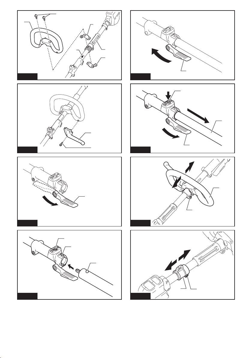
►Fig.5: 1.Lock-offlever2.Switchtrigger
Tostartthetool,turnonthemainpowerswitchand
graspthehandle(thelock-offleverisreleasedbythe
grasp)andthenpulltheswitchtrigger.Toolspeedis
increasedbyincreasingthepressureontheswitch
trigger.Tostopthetool,releasetheswitchtrigger.
Speed adjusting
Youcanadjustthetoolspeedbytappingthemain
powerbutton.
Eachtimeyoutapthemainpowerbutton,thelevelof
speed will change.
►Fig.6: 1.Mainpowerbutton
Indicator Mode
High
Medium
Low
Reverse button for debris removal
WARNING: Switch off the tool and remove
the battery cartridge before you remove entan-
gled weeds or debris which the reverse rotation
function can not remove.Failuretoswitchoffand
removethebatterycartridgemayresultinserious
personalinjuryfromaccidentalstart-up.
Thistoolhasareversebuttontochangethedirectionof
rotation.Itisonlyforremovingweedsanddebrisentan-
gled in the tool.
Toreversetherotation,tapthereversebuttonandpull
thetriggerwhenthetool’sheadisstopped.Thepower
lampstartsblinking,andthetool'sheadrotatesin
reversedirectionwhenyoupulltheswitchtrigger.
Toreturntoregularrotation,releasethetriggerandwait
untilthetool'sheadstops.
►Fig.7: 1.Reversebutton
NOTE: During the reverse rotation, the tool operates
onlyforashortperiodoftimeandthenautomatically
stops.
NOTE: Once the tool is stopped, the rotation returns
toregulardirectionwhenyoustartthetoolagain.
NOTE:Ifyoutapthereversebuttonwhilethetool's
headisstillrotating,thetoolcomestostopandtobe
readyforreverserotation.
Electronic torque control function
Thetoolelectronicallydetectsasuddendropinthe
rotationspeedwhichmaycauseakickback.Inthis
situation,thetoolautomaticallystopstopreventfurther
rotationofcuttingtool.Torestartthetool,releasethe
switchtrigger.Clearthecauseofsuddendropinthe
rotation speed and then turn the tool on.
NOTE:Thisfunctionisnotapreventivemeasurefor
kickbacks.

11 ENGLISH
ASSEMBLY
WARNING: Always be sure that the tool is
switched off and battery cartridge is removed
before carrying out any work on the tool.Failureto
switchoffandremovethebatterycartridgemayresult
inseriouspersonalinjuryfromaccidentalstart-up.
WARNING: Never start the tool unless it is
completely assembled.Operationofthetoolina
partiallyassembledstatemayresultinseriousper-
sonalinjuryfromaccidentalstart-up.
Mounting the handle
Attachthehandlewithsuppliedclampsandbolts.Make
surethatthehandleislocatedbetweenthespacerand
the arrow mark. Do not remove or shrink the spacer.
►Fig.8: 1. Handle 2.Hexsocketbolt3. Clamp
4.Spacer5.Arrowmark
Attachthebarrier(countryspecic)tothehandleusing
thescrewonthebarrier.Onceassembled,donot
removethebarrier.
►Fig.9: 1. Barrier 2.Screw
Mounting the attachment pipe
Mount the attachment pipe to the power unit.
1. Turnthelevertowardthecuttingattachment.
►Fig.10: 1. Lever
2. Alignthepinwiththearrowmarkandinsertthe
attachmentpipeuntilthereleasebuttonpopsup.
►Fig.11: 1.Releasebutton2.Arrowmark3.Pin
3. Turnthelevertowardthepowerunit.
►Fig.12: 1. Lever
Makesurethatthesurfaceoftheleverisparalleltothe
pipe.
Toremovethepipe,turnthelevertowardthecutting
attachment and pull the pipe out while pressing down
thereleasebutton.
►Fig.13: 1.Releasebutton2. Lever 3.Pipe
Adjusting the handle/hanger
position
Adjustthehandleandhangerpositiontoobtainconfort-
ablehandlingofthetool.
Loosenthehexsocketheadboltonthehandle.Move
thehandletoacomfortableworkingpositionandthen
tightenthebolt.
►Fig.14: 1. Handle 2.Hexsocketheadbolt
Loosenthehexsocketheadboltonthehanger.Move
thehangertoacomfortableworkingpositionandthen
tightenthebolt.
►Fig.15: 1.Hexsocketheadbolt2. Hanger
Attaching shoulder harness
WARNING: Be extremely careful to maintain
control of the tool at all times. Do not allow the
tool to be deected toward you or anyone in the
work vicinity.Failuretokeepcontrolofthetool
couldresultinseriousinjurytothebystanderandthe
operator.
CAUTION: Always use the shoulder harness
attached. Before operation, adjust the shoulder
harness according to the user size to prevent
fatigue.
Puttheshoulderharnessonyourleftshoulderbyput-
tingyourheadandrightarmthroughit.Keepthetoolon
yourrightside.
Afterputtingtheshoulderharness,attachittothetool
byconnectingthebucklesprovidedonboththetool
hookandtheharness.Besurethatthebucklesclick
andlockcompletelyinplace.
Adjustthestraptothesuitablelengthforyouroperation.
►Fig.16: 1. Hanger 2. Hook
Thebuckleisprovidedwithameansofquickrelease
whichcanbeaccomplishedbysimplysqueezingthe
sidesandthebuckle.
►Fig.17: 1. Buckle
Hex wrench storage
CAUTION: Be careful not to leave the hex
wrench inserted in the tool head. Itmaycause
injuryand/ordamagetothetool.
Whennotinuse,storethehexwrenchasillustratedto
keepitfrombeinglost.
►Fig.18: 1. Handle 2.Hexwrench
MAINTENANCE
WARNING: Always be sure that the tool is
switched off and battery cartridge is removed
before attempting to perform inspection or main-
tenance on the tool.Failuretoswitchoffandremove
thebatterycartridgemayresultinseriouspersonal
injuryfromaccidentalstart-up.
NOTICE: Never use gasoline, benzine, thinner,
alcohol or the like. Discoloration, deformation or
cracks may result.

12 ENGLISH
Battery guard
WARNING: Do not remove the battery
guard. Do not use the tool with the battery guard
removed or damaged.Directimpacttothebattery
cartridgemaycausebatterymalfunctionandresult
ininjuryand/orre.Ifthebatteryguardisdeformed
ordamaged,contactyourauthorizedservicecenter
forrepairs.
►Fig.19: 1.Batteryguard
TomaintainproductSAFETYandRELIABILITY,
repairs,anyothermaintenanceoradjustmentshould
beperformedbyMakitaAuthorizedorFactoryService
Centers,alwaysusingMakitareplacementparts.
TROUBLESHOOTING
Beforeaskingforrepairs,conductyourowninspectionrst.Ifyoundaproblemthatisnotexplainedinthemanual,
donotattempttodismantlethetool.Instead,askMakitaAuthorizedServiceCenters,alwaysusingMakitareplace-
mentpartsforrepairs.
State of abnormality Probable cause (malfunction) Remedy
Motor does not run. Batterycartridgeisnotinstalled. Installthebatterycartridge.
Batteryproblem(undervoltage) Rechargethebattery.Ifrechargingisnoteffective,
replacebattery.
Thedrivesystemdoesnotwork
correctly.
Askyourlocalauthorizedservicecenterforrepair.
Motorstopsrunningafteralittleuse. Rotation is in reverse. Changethedirectionofrotationwiththereversing
switch.
Battery'schargelevelislow. Rechargethebattery.Ifrechargingisnoteffective,
replacebattery.
Overheating. Stopusingoftooltoallowittocooldown.
ItdoesnotreachmaximumRPM. Batteryisinstalledimproperly. Installthebatterycartridgeasdescribedinthis
manual.
Batterypowerisdropping. Rechargethebattery.Ifrechargingisnoteffective,
replacebattery.
Thedrivesystemdoesnotwork
correctly.
Askyourlocalauthorizedservicecenterforrepair.
OPTIONAL
ACCESSORIES
CAUTION: These accessories or attachments
are recommended for use with your Makita tool
specied in this manual.Theuseofanyother
accessoriesorattachmentsmightpresentariskof
injurytopersons.Onlyuseaccessoryorattachment
foritsstatedpurpose.
Ifyouneedanyassistanceformoredetailsregard-
ingtheseaccessories,askyourlocalMakitaService
Center.
Referto"Approvedattachment"sectionfortheapplica-
blemodelsforthistool.
• Edgerattachment
• Brushcutterattachment
• Stringtrimmerattachment
• Hedgetrimmerattachment
• Groundtrimmerattachment
• Polesawattachment
• Coffeeharvesterattachment
• Cultivatorattachment
• Shaftextensionattachment
• Makitagenuinebatteryandcharger
NOTE:Someitemsinthelistmaybeincludedinthe
toolpackageasstandardaccessories.Theymay
differfromcountrytocountry.

13 FRANÇAIS
FRANÇAIS (Instructions originales)
SPÉCIFICATIONS
Modèle : DUX60
Vitesse à vide
(sans accessoire)
Faible 0 - 5 700 min-1
Moyen 0 - 8 200 min-1
Élevé 0 - 9 700 min-1
Longueur totale 1 011 mm
Tensionnominale 36 V CC
Poidsnet 4,1 kg - 8,7 kg
• Étantdonnél’évolutionconstantedenotreprogrammederechercheetdedéveloppement,lesspécications
contenuesdanscemanuelsontsujettesàmodicationsanspréavis.
• Lesspécicationspeuventvariersuivantlespays.
• Lepoidspeutêtredifférentselonlesaccessoires,notammentlabatterie.Lesassociationslapluslégèreetla
pluslourde,conformémentàlaprocédureEPTA01/2014,sontindiquéesdansletableau.
Batterie applicable
BL1815N/BL1820/BL1820B/BL1830/BL1830B/BL1840/BL1840B/BL1850/BL1850B/BL1860B
• Certainesbatteriesrépertoriéesci-dessuspeuventnepasêtredisponiblesselonlarégionoùvousrésidez.
AVERTISSEMENT : N’utilisez que les batteries répertoriées ci-dessus.L’utilisationden’importequelle
autrebatteriepeutprovoquerdesblessureset/ouunincendie.
Vitesse à vide avec accessoire
Modèle Vitesse de rotation
Faible Moyen Élevé
EM401MP 0 - 4 200 min-1 0 - 6 000 min-1 0 - 7 100 min-1
EM404MP,EM406MP 0 - 3 500 min-1 0 - 5 000 min-1 0 - 6 000 min-1
EN401MP,EN410MP,EN420MP 0 - 2 400 min-1 0 - 3 400 min-1 0 - 4 000 min-1
EY401MP(vitessedechaîne) 0-12m/s 0-17m/s 0-20m/s
KR400MP 0 - 160 min-1 0 - 230 min-1 0 - 280 min-1
EE400MP 0 - 2 800 min-1 0 - 4 000 min-1 0 - 4 700 min-1
EJ400MP 0 - 1 600 min-1 0 - 2 300 min-1 0 - 2 800 min-1
Accessoire approuvé
Type Modèle
TêteDébroussailleuse EM401MP,EM404MP
TêteCoupeHerbe EM406MP
TêteTaille-HaieàPerche EN401MP,EN410MP
TêteFaucheuse EN420MP
TêteÉlagueuseàPerche EY401MP
TêteMoto-Bineuse KR400MP
TêteDresse-Bordures EE400MP
TêtePeigneVibreurPourCafé EJ400MP
Rallonged’Arbre LE400MP

14 FRANÇAIS
Symboles
Voustrouverezci-dessouslessymbolesutiliséspour
l’appareil.Veillezàcomprendreleursignicationavant
toute utilisation.
Lire le mode d’emploi.
Veuillezêtreprudentetresterattentif.
Nepasexposeràl’eau.
Ni-MH
Li-ion
Uniquementpourlespayseuropéens
Nejetezpaslesappareilsélectriquesou
lesbatteriesavecvosorduresménagères!
Conformémentauxdirectiveseuropéennes
relativesauxdéchetsd’équipements
électriquesetélectroniquesetauxpiles
etaccumulateursainsiqu’auxdéchetsde
piles et d’accumulateurs et leur mise en
œuvreconformémentauxloisnationales,
leséquipementsélectriquesetlespileset
batteriesenndeviedoiventfairel’objet
d’unecollectesélectiveetêtreconésà
uneusinederecyclagerespectueusede
l’environnement.
Utilisations
Cemoteurmulti-fonctionssanslestconçupour
entraînerunaccessoireapprouvédanslasection«
SPÉCIFICATIONS»decemanueld’instructions.Ne
jamaisutiliserl’unitédansunautrebut.
AVERTISSEMENT : Lire le manuel d’instruc-
tions de l’accessoire, ainsi que ce manuel d’ins-
tructions avant toute utilisation. Le non-respect
desavertissementsetdesinstructionspeutentraîner
degravesblessures.
Bruit
Accessoire Niveau de pression
sonore moyenne
Niveau de puissance
sonore moyenne
Norme
applicable
LPA (dB (A))
Incertitude
K (dB (A))
LWA (dB (A))
Incertitude
K (dB (A))
EM401MP(commedébroussailleuse) 78,5 1,0 90,2 1,5 EN11806
EM401MP
(commecoupeherbe)
Têtedecoupeàlnylon 84,3 0,6 93,3 1,6 EN50636
Lameenplastique 77.0 1,7 88,5 1,8 EN50636
EM404MP(commedébroussailleuse) 82,5 2,2 93,3 2,9 EN11806
EM404MP
(commecoupeherbe)
Têtedecoupeàlnylon 84,7 2,3 92,8 1,6 EN50636
Lameenplastique 76.0 1,8 87,7 1,5 EN50636
EM406MP Têtedecoupeàlnylon 84,7 2,5 93,5 2,2 EN50636
Lameenplastique 77.0 1,9 85,6 2.0 EN50636
EN401MP 83,7 1,2 92,6 0,7 ISO10517
EN401MP+LE400MP 83,7 1,3 92,8 1,1 ISO10517
EN410MP 80,2 1,9 88,2 2,2 ISO10517
EN410MP+LE400MP 78,9 1,7 88,3 2,7 ISO10517
EN420MP 84,0 0,8 94,0 0,7 ISO10517
EY401MP 92,5 1,4 101,9 1,4 ISO11680
EY401MP+LE400MP 86,6 1,0 101,2 1,0 ISO11680
KR400MP 76,7 2,2 84,2 1,0 EN709
EE400MP 74,8 1,5 88,2 2,6 ISO11789
EJ400MP 87,4 1,4 94,5 1,3 ISO10517
EJ400MP+LE400MP 85,6 1,0 95,5 1,3 ISO10517
• Mêmesileniveaudepressionsonoreindiquéci-dessusestinférieurouégalà80dB(A),leniveauenfonction-
nementpeutdépasser80dB(A).Portezunserre-têteantibruit.

15 FRANÇAIS
Vibration
Accessoire Poignée gauche
(prise avant)
Poignée droite
(prise arrière)
Norme
applicable
ah (m/s2) Incertitude
K (m/s2)
ah (m/s2) Incertitude
K (m/s2)
EM401MP(commedébroussailleuse) 3,0 1,5 2,5 1,5 EN11806
EM401MP
(commecoupeherbe)
Têtedecoupeàlnylon 5,0 1,5 2,5 1,5 EN50636
Lameenplastique 2,5 1,5 2,5 1,5 EN50636
EM404MP(commedébroussailleuse) 3,0 1,5 2,5 1,5 EN11806
EM404MP
(commecoupeherbe)
Têtedecoupeàlnylon 3,0 1,5 2,5 1,5 EN50636
Lameenplastique 2,5 1,5 2,5 1,5 EN50636
EM406MP Têtedecoupeàlnylon 2,5 1,5 2,5 1,5 EN50636
Lameenplastique 4,0 1,5 2,5 1,5 EN50636
EN401MP 5,5 1,5 3,5 1,5 ISO10517,
EN60745
EN401MP+LE400MP 5,5 1,5 4,0 1,5 ISO10517,
EN60745
EN410MP 4,0 1,5 2,5 1,5 ISO10517,
EN60745
EN410MP+LE400MP 4,5 1,5 2,5 1,5 ISO10517,
EN60745
EN420MP 6,5 1,5 4,0 1,5 ISO10517
EY401MP 2,5 1,5 2,5 1,5 ISO11680
EY401MP+LE400MP 5,5 1,5 2,5 1,5 ISO11680
KR400MP 2,5 1,5 2,5 1,5 EN709
EE400MP 2,5 1,5 2,5 1,5 ISO11789
EJ400MP 4,0 1,5 3,0 1,5 ISO10517
EJ400MP+LE400MP 4,5 1,5 3,0 1,5 ISO10517
NOTE :Lavaleurd’émissiondevibrationsdéclaréeaétémesuréeconformémentàlaméthodedeteststandard
etpeutêtreutiliséepourcomparerlesoutilsentreeux.
NOTE :Lavaleurd’émissiondevibrationsdéclaréepeutaussiêtreutiliséepourl’évaluationpréliminairede
l’exposition.
AVERTISSEMENT :L’émissiondevibrationslorsdel’usageréeldel’outilélectriquepeutêtredifférentede
lavaleurd’émissiondéclarée,suivantlafaçondontl’outilestutilisé.
AVERTISSEMENT :Lesmesuresdesécuritéàprendrepourprotégerl’utilisateurdoiventêtrebaséessur
uneestimationdel’expositiondansdesconditionsréellesd’utilisation(entenantcomptedetouteslescompo-
santesducycled’utilisation,commeparexemplelemomentdesamisehorstension,lorsqu’iltourneàvideetle
moment de son déclenchement).
Déclaration de conformité CE
Pour les pays européens uniquement
LadéclarationdeconformitéCEestfournieenAnnexe
Aàcemoded’emploi.

16 FRANÇAIS
CONSIGNES DE SÉCURITÉ
Consignes de sécurité générales
pour outils électriques
AVERTISSEMENT : Veuillez lire les
consignes de sécurité, instructions, illustrations
et spécications qui accompagnent cet outil
électrique. Le non-respect de toutes les instructions
indiquéesci-dessouspeutentraîneruneélectrocu-
tion,unincendieet/oudegravesblessures.
Conservez toutes les mises en
garde et instructions pour réfé-
rence ultérieure.
Leterme«outilélectrique»danslesavertissements
faitréférenceàl’outilélectriquealimentéparlesecteur
(aveccordond’alimentation)ouàl’outilélectriquefonc-
tionnantsurbatterie(sanscordond’alimentation).
Consignes de sécurité importantes
pour la batterie
1. Avant d’utiliser la batterie, lisez toutes les
instructions et précautions relatives (1) au
chargeur de batterie, (2) à la batterie, et (3) au
produit utilisant la batterie.
2. Ne démontez pas la batterie.
3. Cessez immédiatement l’utilisation si le temps
de fonctionnement devient excessivement
court. Il y a risque de surchauffe, de brûlures,
voire d’explosion.
4.
Si l’électrolyte pénètre dans vos yeux, rincez-les
à l’eau claire et consultez immédiatement un
médecin. Il y a risque de perte de la vue.
5. Ne court-circuitez pas la batterie :
(1) Ne touchez les bornes avec aucun maté-
riau conducteur.
(2)
Évitez de ranger la batterie dans un conteneur
avec d’autres objets métalliques, par exemple
des clous, des pièces de monnaie, etc.
(3)
N’exposez pas la batterie à l’eau ou à la pluie.
Un court-circuit de la batterie peut provoquer
une intensité de courant élevée, une surchauffe,
parfois des brûlures et même une panne.
6. Ne rangez pas l’outil et la batterie dans un
endroit où la température risque d’atteindre ou
de dépasser 50 °C.
7.
Ne jetez pas la batterie au feu même si elle est
sérieusement endommagée ou complètement épui-
sée. La batterie peut exploser au contact du feu.
8.
Évitez de laisser tomber ou de cogner la batterie.
9.
N’utilisez pas la batterie si elle est endommagée.
10. Les batteries au lithium-ion contenues sont
soumises aux exigences de la législation sur
les marchandises dangereuses.
Lors du transport commercial par des tierces
partiesoudestransitairesparexemple,desexi-
gencesspéciquesenmatièred’étiquetageet
d’emballagedoiventêtrerespectées.
Pourlapréparationdel’articleexpédié,ilestnéces-
sairedeconsulterunexpertenmatériaudangereux.
Veuillezégalementrespecterlesréglementations
nationalessusceptiblesd’êtreplusdétaillées.
Recouvrezlescontactsexposésavecdurubanadhésif
oudurubandemasquageetemballezlabatteriedetelle
sortequ’ellenepuissepasbougerdansl’emballage.
11. Suivez les réglementations locales en matière
de mise au rebut des batteries.
12. Utilisez les batteries uniquement avec les
produits spéciés par Makita. L’insertion de
batteriesdansdesproduitsnonconformespeut
provoquerunincendie,unechaleurexcessive,
uneexplosionouunefuitedel’électrolyte.
CONSERVEZ CES INSTRUCTIONS.
ATTENTION : N’utilisez que des batteries
Makita d’origine.L’utilisationdebatteriesdemarque
autrequeMakitaoudebatteriesmodiéespeutpro-
voquerl’explosiondesbatteries,cequiprésenteun
risqued’incendie,dedommagesmatérielsetcorpo-
rels. Cela annulera également la garantie Makita pour
l’outil et le chargeur Makita.
Conseils pour assurer la durée
de vie optimale de la batterie
1. Chargez la batterie avant qu’elle ne soit com-
plètement déchargée. Arrêtez toujours l’outil
et rechargez la batterie quand vous remarquez
que la puissance de l’outil diminue.
2. Ne rechargez jamais une batterie complète-
ment chargée. La surcharge réduit la durée de
service de la batterie.
3.
Chargez la batterie à une température ambiante
comprise entre 10 °C et 40 °C. Avant de charger
une batterie chaude, laissez-la refroidir.
4.
Rechargez la batterie si elle est restée inutilisée
pendant une période prolongée (plus de six mois).
DESCRIPTION DES PIÈCES
►Fig.1
1Batterie 2Levier de sécurité 3Gâchette 4Dispositifdesuspension
5Poignée 6Bouton de dégagement 7Barre de protection
(selonlepays)
8Indicateur de vitesse
9Témoind’alimentation 10 Bouton d’alimentation
principale
11 Bouton de marche
arrière
12 Bandoulière

17 FRANÇAIS
DESCRIPTION DU
FONCTIONNEMENT
AVERTISSEMENT : Assurez-vous toujours
que l’outil est hors tension et que la batterie est
retirée avant de régler ou de vérier le fonctionne-
ment de l’outil.Ennemettantpasl’outilhorstension
etenneretirantpaslabatterie,vousrisqueriez
devousblessergrièvementencasdedémarrage
accidentel.
Insertion ou retrait de la batterie
ATTENTION : Éteignez toujours l’outil avant
de mettre en place ou de retirer la batterie.
ATTENTION : Tenez fermement l’outil et la
batterie lors de la mise en place ou du retrait de
la batterie.Sivousnetenezpasfermementl’outil
etlabatterie,ilspeuventvousglisserdesmains,et
s’abîmerouvousblesser.
►Fig.2: 1.Voyantrouge2. Bouton 3. Batterie
Pourretirerlabatterie,faites-laglisserhorsdel’outil
toutenfaisantglisserleboutonàl’avantdelabatterie.
Pourmettreenplacelabatterie,alignezlalanguettesur
labatterieaveclarainuresurlecompartimentetinsé-
rez-la.Insérez-laàfondjusqu’àcequ’unlégerdéclic
sefasseentendre.Silevoyantrougesurledessusdu
boutonestvisible,celasigniequ’ellen’estpasbien
verrouillée.
ATTENTION : Insérez toujours complètement
la batterie jusqu’à ce que le voyant rouge ne soit
plus visible.Sinon,ellepourraittomberacciden-
tellementdel’outil,aurisquedevousblesseroude
blesserquelqu’unsetrouvantprèsdevous.
ATTENTION : N’insérez pas la batterie de
force.Sielleneglissepasfacilement,c’estquevous
nel’insérezpascorrectement.
Système de protection de l’outil/la
batterie
L’outilestéquipéd’unsystèmedeprotectiondel’outil/la
batterie.Cesystèmecoupeautomatiquementl’alimen-
tation vers le moteur pour prolonger la durée de vie de
l’outiletdelabatterie.Sil’outiloulabatteriesetrouve
dans l’une des situations suivantes, l’outil cessera
automatiquementdefonctionner.
État Témoins
Allumé Éteint Clignotant
Surcharge
Surchauffe
Décharge
excessive
Protection contre la surcharge
Sil’outilestsurchargéparunenchevêtrementdemau-
vaisesherbesoud’autresdébris,lesindicateurs et
intermédiairessemettentàclignoteretl’outils’arrête
automatiquement.
Danscecas,éteignezl’outiletarrêtezlatâcheayant
provoquélasurchargedel’outil.Puisrallumezl’outil
pour reprendre la tâche.
Protection contre la surchauffe de
l’outil ou de la batterie
Encasdesurchauffe,touslesindicateursdevitesse
clignotent.
Encasdesurchauffe,l’outils’arrêteautomatiquement.
Laissezl’outilet/oulabatterierefroidiravantderallumer
l’outil.
Protection contre la décharge totale
de la batterie
Lorsquelachargerestantedelabatteriedevienttrès
faible,l’outils’arrêteautomatiquementetl’indica-
teur clignote.
Sil’outilnefonctionnepasmêmeenactionnant
lesinterrupteurs,retirezlesbatteriesdel’outilet
chargez-les.
Indication de la charge restante de
la batterie
Uniquement pour les batteries avec voyant
lumineux
►Fig.3: 1.Témoins2.Boutondevérication
Appuyezsurleboutondevéricationsurlabatterie
pourindiquerlachargerestantedelabatterie.Les
témoinss’allumentpendantquelquessecondes.

18 FRANÇAIS
Témoins Charge
restante
Allumé Éteint Clignotant
75 % à 100 %
50 % à 75 %
25 % à 50 %
0 % à 25 %
Chargezla
batterie.
Anomalie
possible
delabatterie.
NOTE :Selonlesconditionsd’utilisationetlatem-
pératureambiante,l’indicationpeutêtrelégèrement
différentedelacapacitéréelle.
Interrupteur d’alimentation principale
AVERTISSEMENT : Lorsque vous n’utilisez
pas l’outil, mettez-le toujours hors tension avec
l’interrupteur d’alimentation principale.
Pourmettrel’outilenveille,maintenezenfoncélebouton
d’alimentationprincipalejusqu’àcequelalamped’alimen-
tationprincipales’allume.Pourmettrel’outilhorstension,
appuyezànouveausurleboutond’alimentationprincipale.
►Fig.4: 1. Bouton d’alimentation principale
NOTE : La lampe d’alimentation principale clignote
si la gâchette est actionnée dans des conditions de
non-exploitation.Lalampeclignotesivousactionnez
l’interrupteur d’alimentation principale tout en mainte-
nantlelevierdesécuritéetlagâchetteabaissés.
NOTE :
Cetoutildisposed’unefonctiondemisehorsten-
sionautomatique.Pourévitertoutdémarrageintempestif,
l’interrupteurd’alimentationprincipaleeffectueautomati-
quementunemisehorstensionlorsquelagâchetten’est
pasenclenchéependantuncertaintempsaprèsactionne-
ment de l’interrupteur d’alimentation principale.
Fonctionnement de la gâchette
AVERTISSEMENT : Pour votre sécurité,
cet outil est équipé d’un levier de sécurité qui
empêche son démarrage intempestif. N’utilisez
JAMAIS l’outil s’il fonctionne alors que vous
avez seulement enclenché la gâchette sans avoir
actionné le levier de sécurité. Rapportez l’outil à
notre centre de service après-vente agréé pour le
faire réparer AVANT toute utilisation.
AVERTISSEMENT : NE FIXEZ JAMAIS le
levier de sécurité avec du ruban adhésif et abste-
nez-vous de le mettre hors fonction ou de contre-
carrer son utilité.
ATTENTION : Avant d’insérer la batterie dans
l’outil, vériez toujours que la gâchette fonc-
tionne bien et revient en position d’arrêt lorsque
vous la relâchez.
REMARQUE : Évitez d’appuyer sur la gâchette
avec force lorsque le levier de sécurité n’est pas
enfoncé. Vous risqueriez de briser la gâchette.
Unlevierdesécuritéestfournipourprévenirl’activation
accidentelle de la gâchette.
►Fig.5: 1. Levier de sécurité 2. Gâchette
Pourdémarrerl’outil,actionnezl’interrupteurd’alimenta-
tionprincipaleetsaisissezlapoignée(lelevierdesécu-
ritéestalorsrelâché),puisenclenchezlagâchette.Pour
accroîtrelavitessedel’outil,augmentezlapressionsur
lagâchette.Pourarrêterl’outil,relâchezlagâchette.
Réglage de la vitesse
Vouspouvezréglerlavitessedel’outilentouchantle
boutond’alimentationprincipale.
Chaquefoisquevoustouchezleboutond’alimentation
principale, le niveau de vitesse change.
►Fig.6: 1. Bouton d’alimentation principale
Indicateur Mode
Élevé
Moyen
Faible
Bouton de marche arrière pour le
retrait des débris
AVERTISSEMENT : Mettez l’outil hors
tension et retirez la batterie avant de retirer un
enchevêtrement de mauvaises herbes ou des
débris que la fonction de rotation inverse ne peut
pas retirer.Ennemettantpasl’outilhorstensionet
enneretirantpaslabatterie,vousrisqueriezdevous
blessergrièvementencasdedémarrageaccidentel.
Cetoutilestpourvud’unboutondemarchearrière
permettant de changer le sens de rotation. Il sert uni-
quementàretirerlesmauvaisesherbesetdébrispris
dans l’outil.
Pourinverserlarotation,touchezleboutondemarche
arrièreetenclenchezlagâchetteunefoisquelatête
del’outils’estarrêtée.Letémoind’alimentationsemet
àclignoteretlatêtedel’outiltourneensensinverse
lorsquevousenclenchezlagâchette.
Pourreveniràlarotationnormale,relâchezlagâchette
etattendezquelatêtedel’outils’arrête.

19 FRANÇAIS
►Fig.7: 1.Boutondemarchearrière
NOTE :Pendantlarotationinverse,l’outilnefonc-
tionnequependantunecourtepériodeets’arrête
automatiquement.
NOTE :Unefoisquel’outilestarrêté,larotation
revientausenshabituellorsquevousredémarrez
l’outil.
NOTE :Sivoustouchezleboutondemarchearrière
alorsquelatêtedel’outiltourneencore,l’outils’ar-
rêteenvuedelarotationinverse.
Fonction de contrôle du couple
électronique
L’outildétecteélectroniquementunesoudainebaisse
delavitessederotationsusceptibled’entraînerun
recul.Danscecas,l’outils’arrêteautomatiquement
pouréviterquel’outildecoupecontinuesarotation.
Pourredémarrerl’outil,relâchezlagâchette.Éliminezla
causedelasoudainebaissedelavitessederotationet
mettezl’outilsoustension.
NOTE :Cettefonctionn’estpasunemesuredepré-
vention contre les reculs.
ASSEMBLAGE
AVERTISSEMENT : Assurez-vous toujours
que l’outil est éteint et que la batterie est retirée
avant de procéder à n’importe quelle tâche sur
l’outil.Ennemettantpasl’outilhorstensionetenne
retirantpaslabatterie,vousrisqueriezdevousbles-
sergrièvementencasdedémarrageaccidentel.
AVERTISSEMENT : Ne démarrez l’outil que
si ses pièces sont toutes montées.Sivousutilisez
unoutildontlespiècessontpartiellementmontées,
vousrisqueriezdevousblessergrièvementencasde
démarrage accidentel.
Montage de la poignée
Fixezlapoignéeàl’aidedesdispositifsdeserrage
etdesboulonsfournis.Assurez-vousquelapoi-
gnéeestsituéeentreledispositifd’espacementetla
èche.Neretirezpasouneréduisezpasledispositif
d’espacement.
►Fig.8: 1.Poignée2.Bouloncylindriqueàsixpans
creux3.Dispositifdeserrage4.Dispositif
d’espacement 5.Flèche
Fixezlabarredeprotection(selonlepays)àlapoignée
aumoyendelavissurlabarre.Unefoisqu’elleest
xée,neretirezpaslabarredeprotection.
►Fig.9: 1. Barre de protection 2. Vis
Fixation du tuyau pour accessoire
Fixezletuyaupouraccessoireàl’outilmotorisé.
1. Actionnezlelevierversl’accessoiredecoupe.
►Fig.10: 1. Levier
2. Alignezlagoupilledotéedelaècheetinsérez
letuyaupouraccessoirejusqu’àcequeleboutonde
dégagement apparaisse.
►Fig.11: 1. Bouton de dégagement 2.Flèche
3. Goupille
3. Actionnezlelevierversl’outilmotorisé.
►Fig.12: 1. Levier
Assurez-vousquelasurfacedulevierestparallèleau
tuyau.
Pourretirerletuyau,actionnezlelevierversl’acces-
soiredecoupeettirezsurletuyaupourlesortirtouten
appuyantsurleboutondedégagement.
►Fig.13: 1. Bouton de dégagement 2. Levier
3.Tuyau
Réglage de la position de la poignée
ou du dispositif de suspension
Réglezlapositiondelapoignéeetdudispositifde
suspensionpourobtenirunmaniementconfortablede
l’outil.
Desserrezleboulonàtêtecylindriqueàsixpanscreux
surlapoignée.Déplacezlapoignéesurunepositionde
travailconfortable,puisserrezleboulon.
►Fig.14: 1.Poignée2.Boulonàtêtecylindriqueàsix
panscreux
Desserrezleboulonàtêtecylindriqueàsixpanscreux
surledispositifdesuspension.Déplacezledispositifde
suspensionsurunepositiondetravailconfortable,puis
serrezleboulon.
►Fig.15: 1.Boulonàtêtecylindriqueàsixpanscreux
2.Dispositifdesuspension
Fixation de la bandoulière
AVERTISSEMENT : Redoublez de prudence
pour garder constamment la maîtrise de l’outil. Ne
laissez pas l’outil dévier vers vous ou en direction
de quiconque à proximité de la zone de travail.Si
vousnemaîtrisezpasl’outil,vousrisqueriezdevous
blesseretdeblesserd’autrespersonnes.
ATTENTION : Utilisez toujours la bandoulière
xée. Avant utilisation, la bandoulière doit être
ajustée selon la taille de l’utilisateur pour éviter
la fatigue.
Passezvotretêteetvotrebrasdroitdanslabandoulière
pourlapositionnersurvotreépaulegauche.Maintenez
l’outil du côté droit de votre corps.
Aprèsavoirmislabandoulière,xez-laàl’outilenrac-
cordantlesbouclesdisposéessurlecrochetdel’outilet
surlabandoulière.Assurez-vousquelesboucless’en-
clenchentetseverrouillentcomplètement.
Réglezlabandoulièreàlalongueuradaptéeàvotre
utilisation.

20 FRANÇAIS
►Fig.16: 1.Dispositifdesuspension2. Crochet
Laboucleestpourvued’unsystèmed’ouverturerapide
quipeutêtreactionnésimplementenappuyantsurles
côtésetsurlaboucle.
►Fig.17: 1. Boucle
Rangement de la clé hexagonale
ATTENTION : Veillez à ne pas laisser la clé
hexagonale insérée dans la tête de l’outil. Cela
peutprovoquerdesblessureset/ouendommager
l’outil.
Lorsquevousn’utilisezpaslacléhexagonale,rangez-la
comme illustré pour éviter de la perdre.
►Fig.18: 1.Poignée2.Cléhexagonale
ENTRETIEN
AVERTISSEMENT : Assurez-vous toujours
que l’outil est hors tension et que la batterie est
retirée avant d’effectuer tout travail d’inspection
ou d’entretien sur l’outil.Ennemettantpasl’outil
horstensionetenneretirantpaslabatterie,vous
risqueriezdevousblessergrièvementencasde
démarrage accidentel.
REMARQUE : N’utilisez jamais d’essence, ben-
zine, diluant, alcool ou autre produit similaire.
Cela risquerait de provoquer la décoloration, la
déformation ou la ssuration de l’outil.
Protecteur de batterie
AVERTISSEMENT : Ne retirez pas le protec-
teur de batterie. N’utilisez pas l’outil lorsque le
protecteur de batterie est retiré ou détérioré. Un
chocdirectsurlabatteriepeutentraînerundysfonc-
tionnementdecelle-ci,cequipeutprovoquerune
blessureet/ouunincendie.Sileprotecteurdebatte-
rieestdéforméoudétérioré,contactezvotrecentre
deserviceaprès-venteagréépourlesréparations.
►Fig.19: 1.Protecteurdebatterie
PourassurerlaSÉCURITÉetlaFIABILITÉduproduit,
toute réparation, tout travail d’entretien ou de réglage
doiventêtreeffectuésparuncentred’entretienMakita
agréé,avecdespiècesderechangeMakita.
GUIDE DE DÉPANNAGE
Avantdefaireunedemandederéparation,effectuezd’abordvous-mêmeuneinspection.Sivousrencontrezun
problèmenondocumentédanslemoded’emploi,n’essayezpasdedémonterl’outil.Demandezplutôtàuncentre
deserviceaprès-venteMakitaagrééd’effectuerlaréparationaumoyendepiècesderechangeMakita.
État d’anomalie Cause probable (dysfonctionnement) Solution
Le moteur ne tourne pas. Labatterien’estpasinstallée. Installezlabatterie.
Problèmedebatterie(soustension) Rechargezlabatterie.Sivousn’arrivezpasà
rechargerlabatterie,remplacez-la.
Lemécanismed’entraînementne
fonctionnepascorrectement.
Demandezàvotrecentredeserviceaprès-vente
localagrééd’effectuerlaréparation.
Lemoteurs’arrêteauboutd’uncourt
moment.
La rotation est inversée. Changezlesensderotationàl’aidedulevierde
l’inverseur.
Lachargedelabatterieestfaible. Rechargezlabatterie.Sivousn’arrivezpasà
rechargerlabatterie,remplacez-la.
Surchauffe. Arrêtezd’utiliserl’outilpourlelaisserrefroidir.
Il ne tourne pas à plein régime. Labatterien’estpasbieninstallée. Installezlabatteriecommedécritdanscemode
d’emploi.
Labatteriefaiblit. Rechargezlabatterie.Sivousn’arrivezpasà
rechargerlabatterie,remplacez-la.
Lemécanismed’entraînementne
fonctionnepascorrectement.
Demandezàvotrecentredeserviceaprès-vente
localagrééd’effectuerlaréparation.
Other manuals for DUX60
10
Table of contents
Languages:
Other Makita Power Tools manuals

Makita
Makita DJS161 User manual

Makita
Makita ST113D User manual

Makita
Makita JS3200 User manual

Makita
Makita DTR181 User manual

Makita
Makita HK0500 User manual

Makita
Makita 6704D User manual

Makita
Makita JS1602 User manual

Makita
Makita HM0810B User manual

Makita
Makita DJR181 User manual

Makita
Makita JS1000 User manual

Makita
Makita DHR263 Manual

Makita
Makita HM1317C User manual

Makita
Makita TM3000CX4 User manual

Makita
Makita RP0900 User manual

Makita
Makita 1806B User manual

Makita
Makita BTM50 User manual

Makita
Makita XSH06 User manual

Makita
Makita BJN160 Manual

Makita
Makita JN1601 User manual

Makita
Makita HK0500 User manual