6
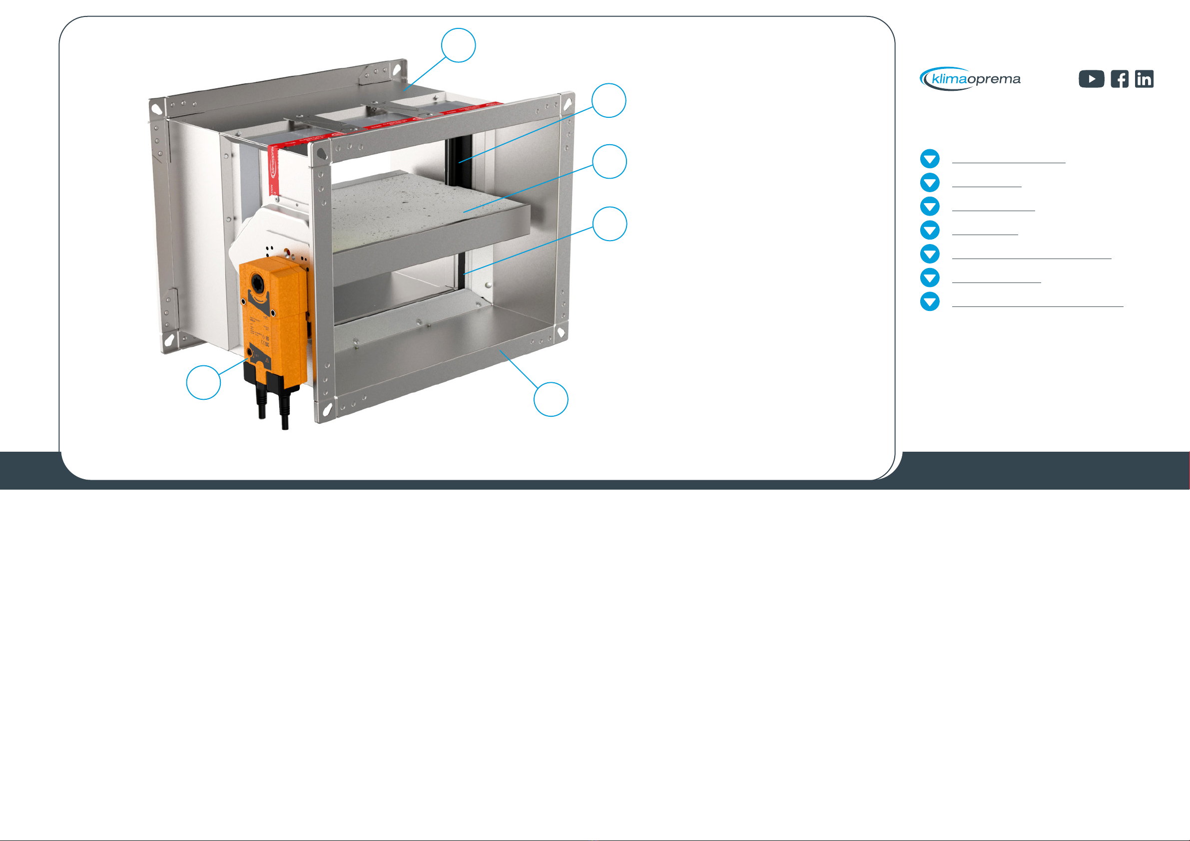
PRODUCT OVERVIEW
DIMENSIONS
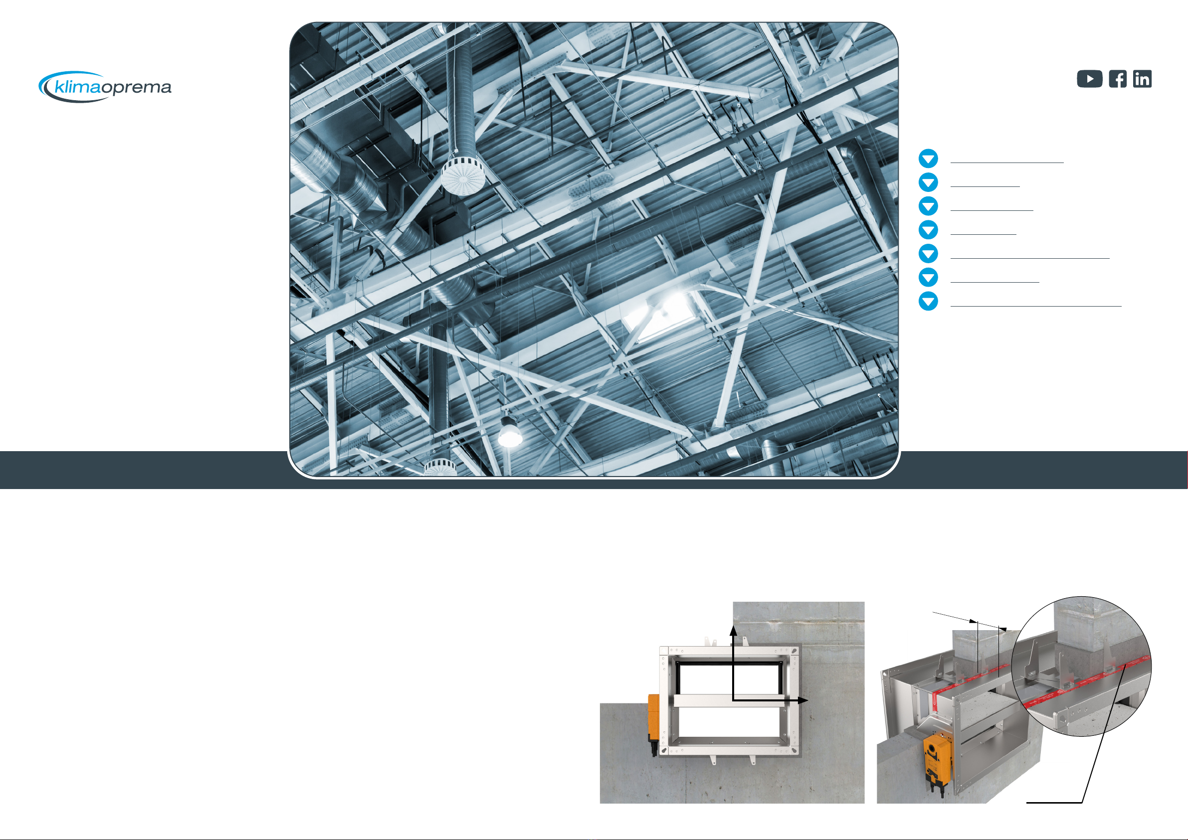
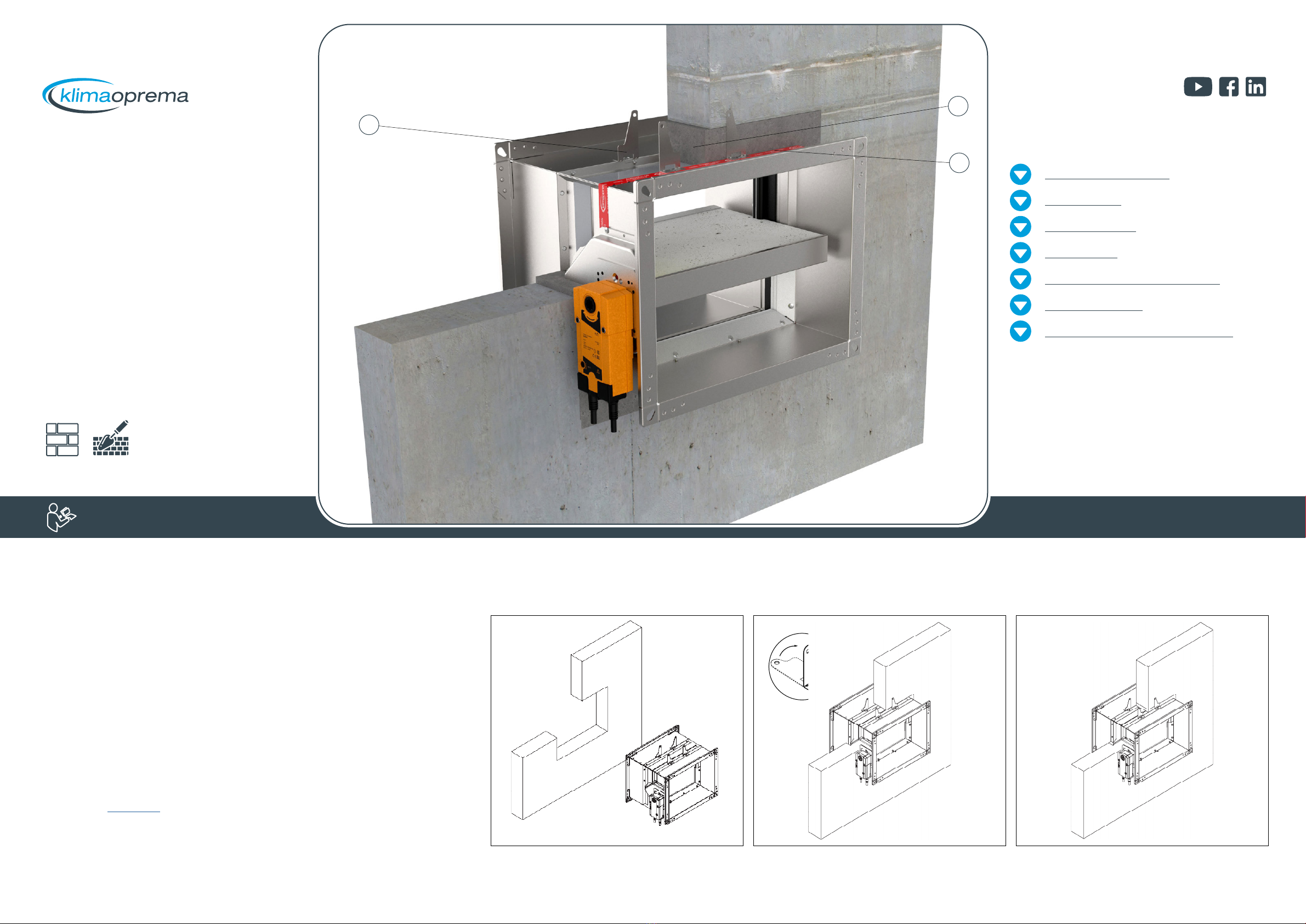
INSTALLATIONS
ACTUATORS
COMMUNICATIONS MODULES
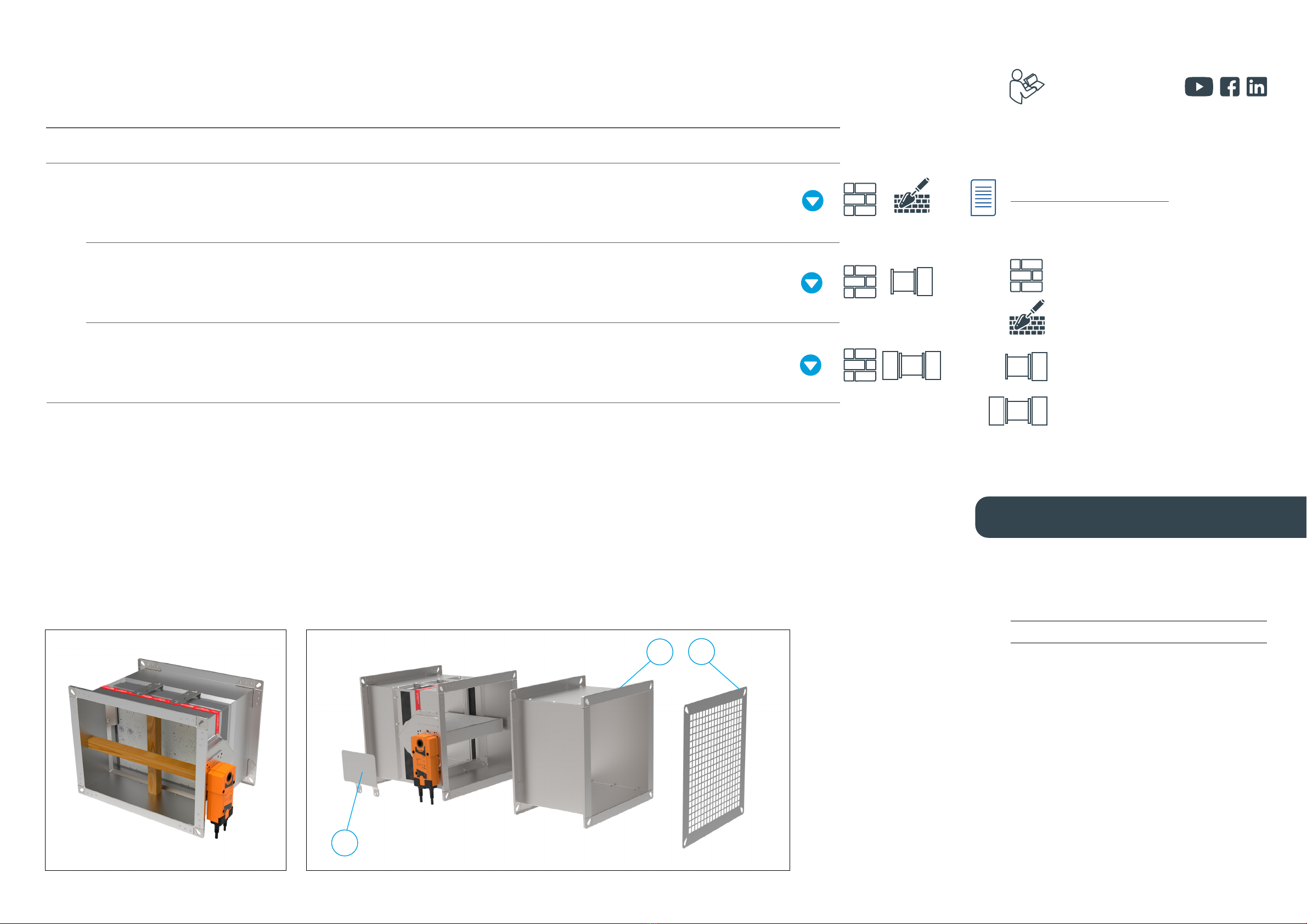
REPLACEMENTS
MAINTENANCE AND OPERATION
DIMENSIONS
FDSD Weight [kg]
H/B 100 150 200 250 300 350 400 450 500 550 600 650 700 750 800 850 900 950 1000 1050 1100 1150 1200 1250 1300 1350 1400 1450 1500
200 6,8 7,5 8,2 8,9 9,7 10,4 11,1 11,8 12,6 14,0 14,7 15,5 16,2 16,2 16,9 17,6 18,3 19,1 19,8 20,5 21,3 22,0 22,7 23,4 24,2 24,9 25,6
250 6,2 6,9 7,5 8,3 9,1 9,9 10,7 11,6 12,4 13,2 14,0 15,6 16,5 17,3 18,1 18,2 19,0 19,8 20,7 21,5 22,3 23,2 24,0 24,8 25,6 26,5 27,3 28,1 29,0
300 6,9 7,6 8,2 9,1 10,0 10,9 11,8 12,7 13,6 14,5 15,4 17,3 18,2 19,1 20,0 20,2 21,1 22,1 23,0 23,9 24,9 25,8 27,5 28,4 29,3 30,3 31,2 32,1 33,0
350 7,6 8,2 8,9 9,9 10,9 11,9 12,9 13,9 14,9 15,9 16,9 18,9 19,9 20,9 22,0 22,2 23,3 24,3 25,3 26,4 27,4 28,4 30,2 31,2 32,3 33,3 34,3 35,3 36,4
400 8,2 8,9 9,7 10,7 11,8 12,9 14,0 15,1 16,2 17,3 18,3 20,5 21,6 22,8 23,9 25,0 26,2 27,3 28,4 29,5 30,7 31,8 32,9 34,1 35,2 36,3 37,4 38,6 39,7
450 8,9 9,6 10,4 11,6 12,7 13,9 15,1 16,3 17,4 18,6 19,8 22,1 23,4 24,6 25,8 27,1 28,3 29,5 30,7 32,0 33,2 34,4 35,7 36,9 38,1 39,3 40,6 41,8 43,0
500 9,6 10,3 11,1 12,4 13,6 14,9 16,2 17,4 18,7 20,0 21,2 23,8 25,1 26,4 27,8 29,1 30,4 31,7 33,1 34,4 35,7 37,1 38,4 39,7 41,0 42,4 43,7 45,0 46,5
550 10,2 11,0 11,8 13,2 14,5 15,9 17,3 18,6 20,0 21,3 22,7 25,4 26,8 28,3 29,7 31,1 32,5 34,0 35,4 36,8 38,3 39,7 41,1 42,5 44,0 45,5 46,9 48,4 49,8
600 10,9 11,7 12,6 14,0 15,4 16,9 18,3 19,8 21,2 22,7 24,1 27,0 28,6 30,1 31,6 33,1 34,7 36,2 37,7 39,3 40,8 42,3 43,8 45,5 47,0 48,5 50,1 51,6 53,1
650 11,9 11,9 14,0 15,6 17,3 18,9 20,5 22,1 23,8 25,4 27,0 28,7 30,3 31,9 33,5 35,2 36,8 38,4 40,1 41,7 43,3 45,1 46,7 48,3 49,9 51,6 53,2 54,8 56,4
700 11,9 12,9 14,7 16,5 18,2 19,9 21,6 23,4 25,1 26,8 28,6 30,3 32,0 33,7 35,5 37,2 38,9 40,7 42,4 44,2 46,0 47,7 49,4 51,1 52,9 54,6 56,3 58,0 59,8
750 12,9 12,9 15,5 17,3 19,1 20,9 22,8 24,6 26,4 28,3 30,1 31,9 33,7 35,6 37,4 39,2 41,1 42,9 44,8 46,7 48,5 50,3 52,1 54,0 55,8 57,6 59,4 61,3 63,1
800 13,9 13,9 16,2 18,1 20,0 22,0 23,9 25,8 27,8 29,7 31,6 33,5 35,5 37,4 39,3 41,3 43,2 45,2 47,2 49,1 51,0 52,9 54,9 56,8 58,7 60,6 62,6 64,5 66,4
Pressure drop tables
ZETA VALUES FDSD
H/B 200 250 300 350 400 450 500 550 600 650 700 750 800 850 900 950 1000 1050 1100 1150 1200 1250 1300 1350 1400 1450 1500
200 11,64 9,56 7,48 6,91 6,33 5,71 5,09 5,06 5,04 4,75 4,46 4,45 4,44 4,42 4,39 4,11 3,84 3,83 3,81 3,80 3,79 3,74 3,69 3,69 3,69 3,67 3,66
250 8,58 7,11 5,65 5,20 4,76 4,29 3,82 3,80 3,78 3,56 3,33 3,32 3,31 3,29 3,27 3,07 2,86 2,85 2,84 2,83 2,83 2,80 2,78 2,78 2,78 2,77 2,76
300 5,51 4,67 3,83 3,50 3,18 2,86 2,55 2,54 2,53 2,36 2,20 2,19 2,18 2,17 2,15 2,02 1,89 1,88 1,86 1,86 1,86 1,86 1,86 1,86 1,86 1,86 1,86
350 4,47 3,78 3,10 2,84 2,58 2,32 2,07 2,05 2,03 1,91 1,78 1,77 1,76 1,75 1,75 1,64 1,53 1,52 1,52 1,51 1,51 1,51 1,51 1,51 1,51 1,51 1,51
400 3,42 2,89 2,37 2,17 1,98 1,78 1,59 1,56 1,53 1,45 1,36 1,35 1,34 1,34 1,34 1,26 1,17 1,17 1,17 1,16 1,15 1,15 1,15 1,15 1,15 1,15 1,15
450 2,91 2,47 2,02 1,85 1,67 1,50 1,33 1,31 1,30 1,23 1,15 1,15 1,14 1,14 1,14 1,07 1,00 1,00 1,00 0,99 0,97 0,97 0,97 0,97 0,97 0,97 0,97
500 2,40 2,04 1,68 1,52 1,36 1,21 1,07 1,07 1,07 1,00 0,94 0,94 0,94 0,94 0,94 0,88 0,82 0,82 0,82 0,81 0,80 0,80 0,80 0,80 0,80 0,80 0,80
550 2,13 1,81 1,48 1,35 1,22 1,09 0,97 0,95 0,93 0,88 0,82 0,82 0,82 0,82 0,82 0,76 0,71 0,71 0,71 0,70 0,70 0,70 0,70 0,70 0,70 0,69 0,68
600 1,86 1,57 1,28 1,18 1,08 0,97 0,87 0,84 0,80 0,76 0,71 0,70 0,69 0,69 0,69 0,64 0,59 0,59 0,59 0,59 0,59 0,59 0,59 0,59 0,59 0,58 0,57
650 1,10 1,02 0,93 0,85 0,77 0,74 0,70 0,66 0,62 0,62 0,61 0,61 0,61 0,57 0,53 0,53 0,53 0,53 0,53 0,53 0,52 0,52 0,52 0,51 0,50
700 0,93 0,85 0,78 0,72 0,67 0,63 0,60 0,57 0,53 0,53 0,53 0,53 0,53 0,50 0,47 0,47 0,47 0,47 0,47 0,46 0,45 0,44 0,44 0,44 0,44
750 0,75 0,71 0,65 0,60 0,58 0,56 0,53 0,50 0,49 0,47 0,47 0,47 0,44 0,42 0,42 0,42 0,42 0,42 0,41 0,40 0,40 0,40 0,40 0,40
800 0,63 0,58 0,54 0,53 0,52 0,49 0,46 0,44 0,41 0,41 0,41 0,39 0,36 0,36 0,36 0,36 0,36 0,36 0,35 0,35 0,35 0,35 0,35
SMOKE CONTROL DAMPERS
BEN-24/230 BEE-24/230
Pressure drop values are described with the “Zeta” values for
each size. The exact pressure drop in [Pa] is calculated using
the following formula: Δp [Pa]= ζ * v² * 0,6
where ζis Zeta value from the tables below, v is airflow
velocity in [m/s]
H
B