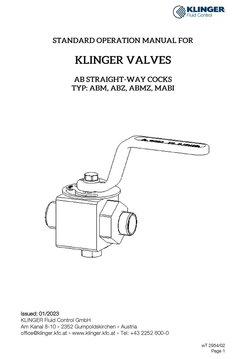
KLINGER MABA User manual

wT 2954/02
Page 1
Issued: 01/2023
KLINGER Fluid Control GmbH
Am Kanal 8-10 » 2352 Gumpoldskirchen » Austria

wT 2954/02
Page 2
Contents
1Declaration of Conformity.............................................................................3
2Individual Parts Designation .........................................................................4
3Proper Use ..................................................................................................5
4Testing of KLINGER Valves..........................................................................5
5Labeling of the Valves ..................................................................................5
6Safety Instructions .......................................................................................6
6.1 General Notes on Safety.............................................................................. 6
6.2 Safety Instructions for Operators ................................................................. 6
6.3 Hazard Warnings......................................................................................... 7
7Technical Data.............................................................................................9
7.1 Material codes............................................................................................. 9
7.2 PT Diagrams ............................................................................................... 9
8Transportation and Storage .......................................................................11
9Operating Principle and Mode of Operation................................................12
10 Installation and Putting into Service Regulations .........................................13
11 Service and Maintenance...........................................................................13
11.1 Resealing .................................................................................................. 14
11.2 Disassembly and Assembly ....................................................................... 15
12 Disposal ....................................................................................................16

wT 2954/02
Page 3
1Declaration of Conformity

wT 2954/02
Page 4
2Individual Parts Designation
1 Body
2 Packing sleeve
3 Cock plug
4 Split ring
5 Tightening nut
6 Locking disc
8 Plug with sealing edge
9 Tightening screw
10 Fillister head screw
11 Disc
12 Hexagon head screw
13 Lever

wT 2954/02
Page 5
3Proper Use
This product is exclusively intended to shut off or convey media within the approved
pressure and temperature limits after installation in a pipeline system. Please see the P/T
diagram (pressure temperature diagram) for the permissible threshold values in
accordance with the utilized materials. This operating manual must unconditionally be
brought to the attention of the corresponding personnel!
Prior to installation and putting into service for the first time, please read the operating
manual carefully and pay attention to the hazard and safety notes!
!
CAUTION
Non-compliance with the hazard and safety notes of this operating
manual may result in the creation of hazards and loss of the
manufacturer's warranty.
Please contact the manufacturer under +43 2252 600-0 for further
details.
Subject to technical alterations and misprints!
4Testing of KLINGER Valves
KLINGER Valves are pressure-tested in accordance with EN 12266-1. The pressure test
comprises the tests P10, P11 and P12. Testing the resistance to pressure of the piston
(P20) is not included in the standard package.
5Labeling of the Valves
Each valve is provided with the following data listed either on the body or on a type
plate.
Designation
Comment
Manufacturer
KLINGER
Please see the operation manual for the
address
Model
e.g. MABU
Manufacturer’s type designation
Size
DN and numeric value
Numeric value in mm, e.g. DN 6
PN / class
Numeric value for PN
/ class
Provides the max. permissible pressure at
ambient temperature, e.g. PN 40
FA-No.
Numbers / letters
FA-No. serves identification purposes
Material
e.g. 1.0619 or VIII
In accordance with material codes
CE
Market approval symbol

wT 2954/02
Page 6
6Safety Instructions
This operation manual must be brought to the attention of the operating personnel.
6.1 General Notes on Safety
The safety instructions for valves also apply to the pipeline systems, into which they are
installed. This operating manual exclusively focuses on safety instructions, which are to
be additionally complied with for valves.
6.2 Safety Instructions for Operators
!
Danger
to Life
A valve with a permissive pressure/temperature range that is not sufficient
for the operating conditions may not be operated! This range is to be derived
from the PT diagram. With regard to materials, pressures or temperatures
not listed there, contacting the manufacturer is mandatory.
Ignoring this regulation can result in life-threatening situations and can
cause damage to the pipeline system.
!
Danger
to Life
It must be ensured that materials selected for the parts coming into contact
with the media are suitable for the utilized media. The manufacturer takes
no responsibility for damages resulting from corrosion or through aggressive
media.
Ignoring this regulation can result in life-threatening situations and can
cause damage to the pipeline system.
The following items do not lie in the scope of responsibility of the manufacturer. As a
consequence, when utilizing the valve, it must be ensured that
»the valve is only utilized in accordance with its proper use, as illustrated under
"Proper Use".
»the actuator unit, which is subsequently mounted on the valve, is adjusted to the
valve and correctly adjusted in the end position.
»when connecting a valve actuator to the power grid, the safety notices of the
actuator manufacturer are complied with.
»the valves are correctly implemented into the system, especially those connected
to the pipeline system by means of welding.
»no additional tensions bear on the valves.
»the operation parameters and operating conditions have been clarified with the
manufacturer of the valve and that operating conditions such as vibrations, water
hammers, pressure surges, erosion etc. are to be avoided.
»pipeline system connections and valves, which are operated at operating
temperatures > 50 °C or < -20 °C, are protected against contact.
»during welding procedures, the safety regulations of the plant operator and/or
plant constructor are to be complied with.
»the valve is only operated and maintained by trained personnel.
»valves, which are utilized with hazardous media (inflammable, corrosive, harmful
to health etc.), are to be handled in accordance with their dangers. The
corresponding handling regulations are the responsibility of the plant operator.
»all ergonomic hazards are to be considered by the plant operator, such as e.g.
accessibility, gauges etc.

wT 2954/02
Page 7
»when applying internal pressure for the first time (pressure test, trial operation) a
sufficient safety distance is to be maintained.
»it is prohibited to open screw connections (with the exception of those on hand
levers and handwheels), when pressurized (medium).
»installation and removal of valves is only carried out with a depressurized and
drained pipeline.
»all connections, following loosening, are again correctly tightened afterwards.
»no screws are loosened on pressure-retaining parts, unless described so in the
operation manual.
»no screwed connections are forcibly opened.
»during longer shutdown periods, in the event of freezing media, the valve is drained
and/or that depressurization is achieved in case of expanding media.
6.3 Hazard Warnings
Mechanical hazards:
»Beware of possible sharp or protruding parts posing risk of injury.
»Extra care is required during putting into operation: Do not reach into the bore
opening during the valve closing process, as this poses a risk of injury.
»Be careful of falling parts during transportation, maintenance and putting into
operation.
»When manipulating lifting appliances, the safety regulations for lifting appliances
must be complied with.
»Unauthorized and improper handling can result in undesired and spontaneous
pressure loss and can result in significant damage.
»With regard to valves featuring a mounting bracket it must be ensured that moving
valve parts do not result in a risk of injury.
Electrical hazards:
»With regard to valves featuring electric actuators, the operating manual and the
safety instructions of the actuator manufacturer must be complied with.
Thermal hazards:
»During operation, the surfaces of valves may feature high / low temperatures.
Caution: Burn hazard.
»Caution: The hot surfaces can cause self-ignition of flammable materials through
either contact or heat emission.
Hazard generated by noise:
»Depending on the application conditions, high levels of noise can be created by
the cavitation processes, which bear the risk of hearing damage.
»Opening an internally pressurized valve can result in major noise exposure as a
result of exiting media; hearing damage hazard.
Vibration hazard:
»Caution: Abrupt opening or closing of a valve can lead to undesired surges and
vibrations in the pipe, which may possibly damage the valve or the pipeline system.

wT 2954/02
Page 8
Electromagnetic radiation hazard:
»The hazards resulting from possibly created electromagnetic radiation are to be
consulted in the operating manual of the actuator manufacturer.
Hazards linked to the operational environment:
»The ambient atmosphere and the ambient temperature are to be set in a manner
that has no negative influence on the valve, the actuator of the valve, and the
medium.
Transportation hazards:
»Please see the chapter “Transportation and Storage” for transportation hazards.
Maintenance hazards:
»All maintenance and repair tasks with the exception of lubricating and subsequent
sealing of stuffing boxes and valve rings are without exception to be carried out in
an unpressurized state. Where required, the valve may have to be drained prior to
servicing.
»Valves may only be removed from pipeline systems in an unpressurized and empty
state.
»Attention must be paid to exiting media when resealing.
»Caution: (Fire and chemical) burn hazard and risk of poisoning caused by valves
utilized in dangerous media. Attention must be paid to medium residues during
maintenance and putting into operation tasks.
»Maintenance and repairs may only be carried out by qualified personnel.
Placing out of operation hazards:
»When placing out of operation, the valves must be emptied fully and attention must
be paid to hazards resulting from medium residue.
»Should valves be no longer used, they are to be disposed of correctly.
Material failure hazard:
»Parts made of grey cast iron are especially sensitive to brittle fracture and impact.
This aspect must be considered in the course of material selection.

wT 2954/02
Page 9
7Technical Data
7.1 Material codes
The main criterion of the material codes is the basic material of the body.
Symbol
Body
Interior Parts
IV
Brass
Nonferrous metal parts possible
VIII
Cast steel
Without nonferrous metal part
X
Stainless steel
Parts coming into contact with
the medium are acid-resistant
The above table may also contain material codes unavailable for this product.
7.2 PT Diagrams
The applicable maximum limitations of use regarding pressure and temperature are
defined by their mutual interdependency. A PT diagram is an ideal tool in order to select
a suitable valve for pre-defined operational characteristics.
0
20
40
60
80
100
120
140
160
180
-300 -200 -100 0100 200 300 400 500
pT-Diagramm IV + VIII
IV PN40 KOR-AF p(bar) VIII PN160 KOR-AF p(bar) VIII PN160 KAF p(bar)

wT 2954/02
Page 10
0
50
100
150
200
250
300
-300 -200 -100 0100 200 300 400 500
pT-Diagramm X
X PN160 KOR-AF p(bar) X PN160 KAF p(bar) X PN250 KAF p(bar)

wT 2954/02
Page 11
8Transportation and Storage
Check the shipment immediately upon receipt for completeness of delivery and transport
damage. Furthermore, it should be ensured that the valves and possibly mounted
actuators have not been damaged during transport. Please also check that the supplied
valves (types, nominal sizes etc.) correspond with the order. KLINGER Fluid Control is to
be notified immediately of any kind of deviations. Regarding damage obviously resulting
from transportation, please contact the freight forwarder in charge of delivery.
Valves and valve replacement parts may only be stored in dry storage areas. Fully
assembled valves must be stored in the condition as supplied to the customer (valve in
CLOSED position, connections covered with protective caps). Valve replacement parts
must be handled with care and should remain as packaged by the factory during storage.
»Storage in the default factory packaging.
»The valves are to be stored in closed rooms, in a non-aggressive atmosphere,
and protected against humidity and contaminants.
»In the event that protective sheeting or shrinking foils are used, it must be
ensured –through adequate measures –that the atmosphere within the covers
remain free of condensation.
»Corresponding protective measures are recommended for storage in dusty
rooms.
»In order to avoid mix-ups, all stored parts should be labeled in accordance with
the shipping notes and stored in the correct place.
»The temperature in the storage rooms should not exceed the limits -20 °C and
+50 °C. Rapid temperature changes are to be avoided whenever possible
(condensate water).
»Possible changes originating from KLINGER Fluid Control and having an impact
on storage will be announced in a timely manner in the form of a circular.
»The operation manual is part of the delivery and must be stored with the item.
This ensures that all important information and documents can be passed on.
»Lift lines suitable for the weight and the lifting aids on the valve (to the extent
present) are to be used for manipulation purposes.
Damages resulting from incorrect storage or manipulation free KLINGER Fluid Control
from any obligations derivable from the warranty, guarantee and product liability.

wT 2954/02
Page 12
9Operating Principle and Mode of Operation
Klinger MAB-series pressure gauge cocks are shut-off fittings which are developed for
measurement technologies.
A cylindrical cock plug and an elastic packing sleeve enable rapid opening and closing
over a 90° travel path.
The unit is activated with a removable lever (also safeguard against unauthorized
activation).
All cocks are closed CLOCKWISE, expect the MABAL model, which is closed counter
clockwise.
The packing sleeve is secured to the body in locked position by a spring and a groove.
An eyelet mounted across the ports keeps the entire cross section intact and protects
the sealing material against erosion.
The large sealing surface of the cock packing sleeve ensures tightness both across the
ports and to the outside.
It is the only wearing part that can be replaced easily and quickly. The fitting itself needs
not to be removed from the tubing.
The cylindrical cock plug is prevented from slipping out of the body by a split ring.
The position of the through hole is visible at the twin edge of the plug, or at the notches
of the cock plug and at the lever.
In the event of leaks, the tightening nut can be used to retighten the packing sleeve in the
open position, observing the necessary tightening torque. This threaded joint is
safeguarded against loosening or manipulation by a locking disc.
MAB cocks can be installed in any position and are not limited to any specific flow-
direction.

wT 2954/02
Page 13
10 Installation and Putting into Service Regulations
In order to protect against impurities and damage, the connections of the valves are
covered. We recommend removal of these covers only prior to installation.
Valves with welding ends may generally be welded into a pipework by means of fusing
welding procedures. In this context, the welding and quality requirements and their norms
are to be complied with. As a consequence, welding may only be carried out by qualified
personnel. The safety regulations of the plant operator and/or the plant manufacturer are
also to be complied with.
Following installation and prior to putting into service, it must be ensured that solids and
impurities, which are not part of the medium, have been removed from the pipeline
system and/or from the facility. A pressure and a function test must be carried out prior
to putting into operation
Prior to putting into service of valves in steam pipes, proper condensate draining must
be ensured in order to avoid steam hammer hazards. In extreme cases, a steam hammer
may lead to breaking of the valve. Rapid increases in temperature and pressure are to be
avoided during all operation phases (start –operation –shutting down).
The maximum permissible test pressure is 1.1 x PN if the piston valve is in a closed state.
The valve must be open when testing the pipe pressure (1.5 x PN).
11 Service and Maintenance
Maintenance and inspection intervals are to be determined by the operator dependent
on the operating mode, as these valves can be utilized under a number of different
operating conditions. Maintenance and inspection work may only be carried out by
trained personnel.
Prior to the start of service and maintenance work, it must be ensured that the pipeline
system is depressurized and that no medium residues are contained within.
When removing an actuator, it is necessary to protect it against rotation prior to loosening
of the connecting screws.

wT 2954/02
Page 14
11.1Resealing
The MAB-cocks are tightened with 35 Nm. At starting apparatus retighten again with 35
Nm, at operation only after demand.
ATTENTION: Resealing is only possible in OPEN position!
»Loosen fillister head screw (item 7)
»Remove locking disc (item 6)
»use tightening nut (item 5) for resealing –tightening torque 35Nm+5Nm
»Put on locking disc in such a way as to allow the mounting of the cap screw
The plug with sealing edge (pos.8) is tightened with 100Nm during montage.
If a MAB cock has developed a leakage and retightening no longer seals the leak, the
packing sleeve must be replaced. If the cock plug is found to be damaged after
disassembly, it must also be replaced
Resealing with 35Nm
10

wT 2954/02
Page 15
11.2Disassembly and Assembly
Disassembly
»Loosen fillister head screw (item 10)
»Remove locking disc (item 6)
»Unscrew tightening nut (item 5)
»Loosen hexagon head screw (item 12), remove disc (item 11) and lever (item 10)
from cock plug (item 3)
»Only for MABAL: Remove secure ring and stop from cock plug (item 3)
»Knock cock plug (item 3) with split ring (item 4) and packing sleeve (item 2) out of
the body (item 1)
»Take off split ring (item 4) and press cock plug (item 3) through the packing sleeve
(item 2)

wT 2954/02
Page 16
Assembly
»Insert split ring (item 4) in the groove of the cock plug (item 3)
»Slide packing sleeve (item 2) onto the cock plug (item 3) up to the split ring (item
4)
»Press the entire unit into the hole of the body
ATTENTION: The packing sleeve spring must rest in the groove of the body hole.
The packing sleeve eyelets may not protrude or lie titled in the packing sleeve through
the hole.
»Screw in the tightening nut (item 5) –tightening torque: 35Nm
»Only for MABAL: Slide the stop onto the cock plug (item 3 and secure it with the
secure ring
»Place the lever (item10) and the disc (item 11) on the cock plug (item 3) and fix
them with the hexagon head screw (item 12)
»Put on the locking disc (item 6), fasten it with the fillister head screw (item 17)
12 Disposal
To the extent that other laws do not require a deviating treatment, the utilized materials
should be separated in accordance with their properties and entered into the raw
materials recycling process. The pre-requirement in this regard is that the raw materials
have been correspondingly decontaminated on the order of the operator.
This manual suits for next models
3
Table of contents
Other KLINGER Control Unit manuals

KLINGER
KLINGER KVN Series User manual

KLINGER
KLINGER INTEC K210-FS Setup guide
KLINGER
KLINGER Ballostar KHE Guide

KLINGER
KLINGER KVN DN 65 User manual
KLINGER
KLINGER 3530 Owner's manual

KLINGER
KLINGER KHD-M4F Series Instruction manual
KLINGER
KLINGER KHD-21E Instruction manual
KLINGER
KLINGER KHD-311FF Instruction manual

KLINGER
KLINGER KVN Series Service manual

KLINGER
KLINGER BALLOSTAR KHA User manual