12-16TON PIPE BENDERS
OWNER’S MANUAL
Assembly
No Assembly required
Before Each Use
• Inspect the work area before each use. Keep work area clean, dry, free of clutter, and well lit.
Cluttered, wet, or dark work areas can result in injury. Using the tool in confined work areas
may put you dangerously close to other cutting tools and rotating parts.
• Check for damaged parts before each use. Carefully check that the tool will operate properly
and perform its intended function. Replace damaged or worn parts immediately. Never
operate the tool with a damaged part.
Operating Instructions
49652 & 49653 – Hydraulic Pipe Benders
• The pipe bender must be placed on a smooth, level surface that is capable of supporting the
weight of the pipe bender, pipe and all accessories.
• Do not exceed the maximum limit of the pipe bender posted on the frame and on the jack.
• Two person operation. For safety, when moving the Pipe Bender or bending large pieces of
pipe, always involve two people. When bending large pipe, one person is needed to balance
the pipe in the bending dies, while a second person operates the bottle jack's handle.
Bending a Pipe
1. Place the pipe bender on a solid, level floor or workbench.
NOTE: If a workbench is selected, use shop clamps to
secure the bender in place and keep it from rocking.
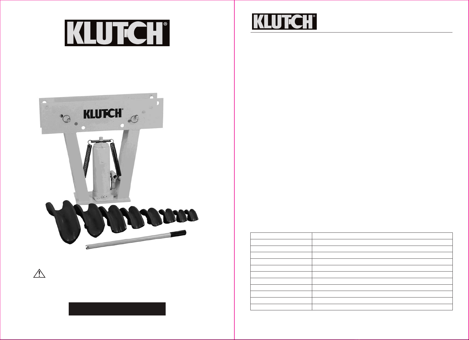
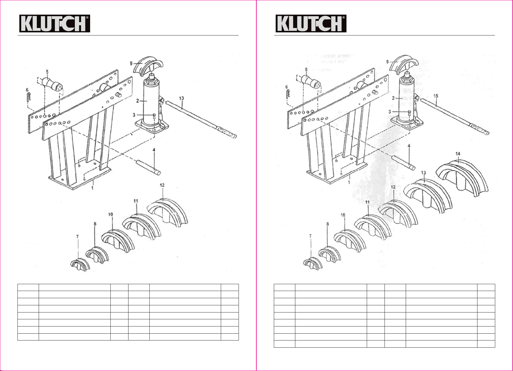
2. Choose the proper size bending die and slip it on the
end of the ram as shown in Figure 1.
3. Choose an angle to bend the pipe.
• 35-45 degree bend: place the rollers (#5) between the
far outside holes on the frame (Figure 2).
• 90 degree bend: place the rollers (#5) further inside
the frame to increase the bending angle.
4. To move the rollers, remove the hitch pins (#6) and roller
shafts (#4) (Figure 2), and place the rollers between
corresponding holes on each side of the frame.
5. Reinstall the roller shafts and hitch pins.
6. Place the pipe over the bending die.
NOTE: To account for pipe shortening during the bend,
make sure the pipe extends beyond the rollers and, for
short pipe, set the rollers closer together.
7. Insert the jack handle into the socket on the tube bender.
8. Make sure the release valve is closed, then use the jack
handle to advance the die and bend the pipe.
9. When finished with the bend, release the pressure by
opening the release valve on the jack. Close the valve
after the ram has fully lowered.
OPERATION TIPS AND TECHNIQUES:
• The pipe bender is designed to bend water pipe and heavy-gauge galvanized pipe that is
used in commercial applications. The bottle jack (#2) is a heavy-duty tool that should last
through several years of use. The only parts that eventually wear out, during normal use, are
the seals. If hydraulic fluid is found to be seeping from the ram of the bottle jack, you can fix
the problem by installing a seal kit (not included).
• If the ram reaches the end of its stroke but still has not completed a desired bend, release
pressure just enough to remove the pipe. Set the rollers either one or two holes farther in
toward center to finish the bend.
4 of 11
12-16TON PIPE BENDERS
OWNER’S MANUAL
• It is recommended that you make templates of accurate 45 and 90 angles. Compare these
templates to an almost-finished pipe so you do not over- or under-bend. Using templates will
speed up your work.
• If you pass the 45 angle mistakenly, you can sometimes reverse the pipe and slightly press it
enough to reach the required 45.
• Bending any angle may thin and stress the walls of the pipe and narrow its center. If you
need to make bends more than 100 degrees, it is recommended that you heat the pipe during
bending. Generally, heat weakens the metal, but it also allows it to bend more freely.
• Pipes bent past 90 will flow into the bending die, making the pipe hard to remove after
bending. Greasing the inside of the die will make this removal easier, or switching to a larger
die for bending the last few degrees will eliminate this difficulty.
• For bends up to 90 degrees for 2 1/2" or 3" tubes, tightly fill the tube with sand and plug both
ends.
49654 – Air/Hydraulic Pipe Bender
• The pipe bender must be placed on a smooth, level surface that is capable of supporting the
weight of the pipe bender, pipe and all accessories.
• Do not exceed the maximum limit of the pipe bender posted on the frame and on the jack.
• Two person operation. For safety, when moving the Pipe Bender or bending large pieces of
pipe, always involve two people. When bending large pipe, one person is needed to balance
the pipe in the bending dies, while a second person operates the bottle jack's handle.
• Bender 49654 (air/hydraulic) should be used with compressed air only. Only use clean, dry
and regulated compressed air. Never use Oxygen, carbon dioxide or any other bottled gas as
a power source for this tool.
Bending a Pipe
1. Place the pipe bender on a solid, level floor or workbench.
NOTE: If a workbench is selected, use shop clamps to
secure the bender in place and keep it from rocking.
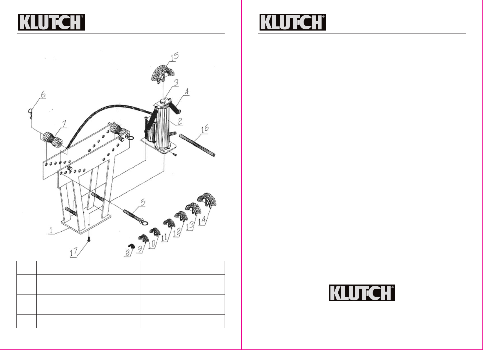
2. Choose the proper size bending die and slip it on the
end of the ram as shown in Figure 1.
3. Turn the bottom relief valve on the jack clockwise until
it is tight to close it.
4. For hydraulic operation, insert the jack handle into the
socket on the tube bender.
For air operation, connect the hose to the air compressor
(see 49654, Using Air Pressure, below).
5. Choose an angle to bend your pipe.
35-45 degree bend: place the rollers (#5) between the far
outside holes on the frame.
90 degree bend: place the rollers (#5) further inside the
frame to increase the bending angle.
6. To move the rollers, remove the hitch pins (#6) and roller
shafts (#5) (Figure 2), and place the rollers between
corresponding holes on each side of the frame.
7. Reinstall the roller shafts and hitch pins.
8. Place the pipe over the bending die.
NOTE: To account for pipe shortening during the bend,
make sure the pipe extends beyond the rollers and, for
short pipe, set the rollers closer together.
10. Make sure the jack release valve is closed, then use the
jack handle or air to advance the die and bend the pipe.
11. When finished with the bend, release the pressure by opening the release valve on the jack.
Close the valve after the ram has fully lowered.
5 of 11