KMART 50cm Racer User manual

Item No.: 43033430
Item Name: 50cm Racer

Contents
1. Parts identification …………………………………… 1
2. Safety precautions 2
3. 5
4.
Assembly
5.
Adjustment
20
6.
Repair and Service
Warranty
……………………………………
……………………………………
……………………………………
……………………………
……………………………………
…
…
…………
16
22

NAME OF RACER PARTS

SAFETY PRECAUTIONS
WARNING TO AVOID SERIOUS INJURY:
Adult assembly is required.
Continuous adult supervision is required.
This product should only be used by persons 8+ years of age.
Never ride with more than one person. Maximum weight is 180 lbs (82Kg).
Excessive weight may cause a hazardous or unstable condition.
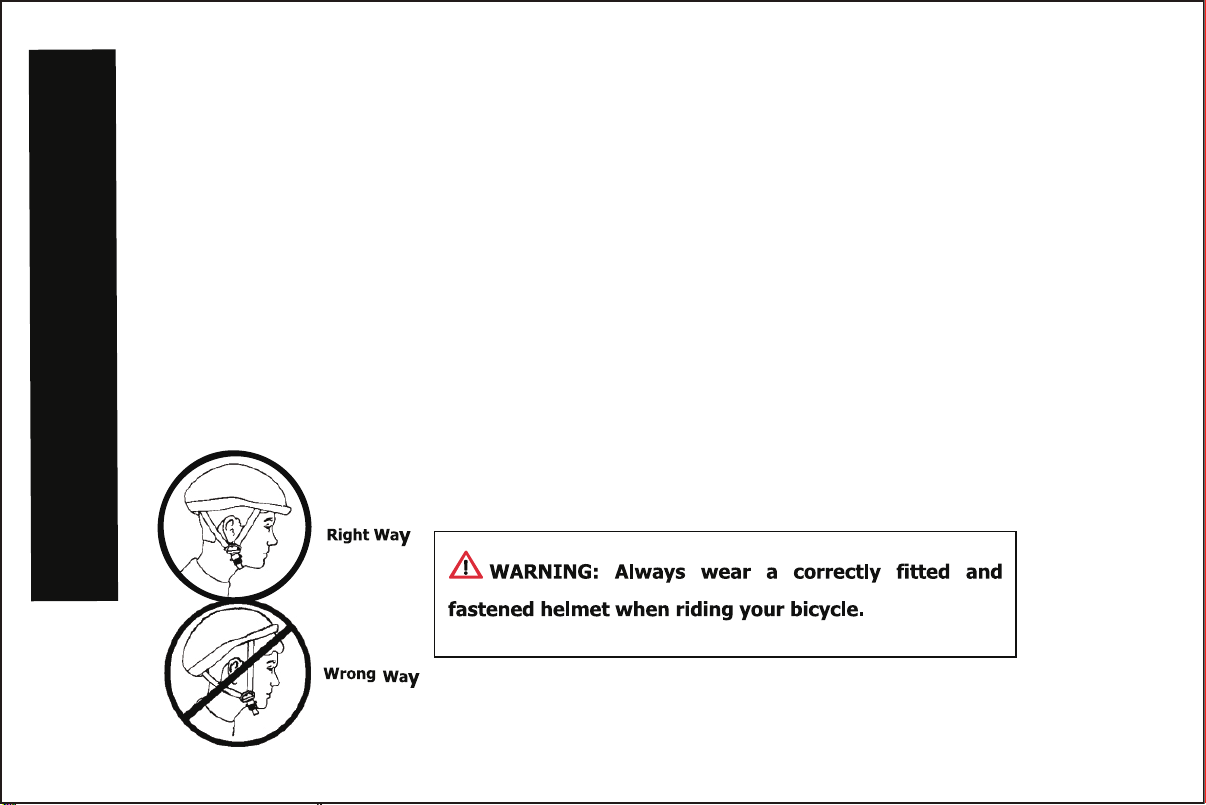
Always wear an approved helmet while riding, with the chinstrap securely fastened.
Always wear shoes when riding.
Always wear kneepads, wrist guards, gloves, and elbow pads when riding.
Do not ride the product at dusk, at night or at times of limited visibility.
Always comply with local laws and regulations.
Ride on smooth paved surfaces. Do not ride on streets or roadways.
Do not ride off road, on grass or wet surfaces.
Never use near motor vehicles.
Do not ride the product over curbs or bumps that can damage the steering mechanism.
Do not ride on hills, steeply sloped areas, on or near steps, near swimming pools, or in alleys.
Not intended for jumping.
The brake may be hot after continuous use. Do not touch after braking.
Check brakes and secure all fasteners before every ride.
Do not wear headphones or anything else that would impair your ability to hear or see.
Understand all operating procedures before riding.
SAFETY PRECAUTIONS
Do not push the product.
Do not tow or pull any objects with the product.
Replace worn or broken parts immediately.
Know your limits. Be familiar with your abilities. Use common sense.
Not suitable for children under 3 years as small parts may cause a choking hazard.
Handlebar hand grips and tube end plugs should be replaced if damaged, as bare tube ends have been known to
cause injury. It is particularly important that bicycles and tricycles used by children are checked regularly to ensure
that adequate protection for the ends of the handlebars are in place.
Replacement forks must have the same rake and tube inner diameter as the original product.
Keep a Record of Your Bicycle
Each tricyle has a Serial Number stamped into the head tube. Write down this number to keep it for future reference.
a colour photograph of your tricycle, write the Serial number on the back of the photograph and keep it in a safe place. If you keep
a record of the details of your tricycle,it will greatly increase the possibility of getting it back should it be lost or stolen.
Take
3

Small Adjustable Wrench
(Jaws must open at least 14mm.)
Open-end Wrenches(8 / 10 / 13mm)
Flat-blade Screwdriver Phillips Screwdriver
Slip-Joint Pliers Metric Allen Wrenches(5 / 6mm)
Torque Wrench (recommended)
NOTE: See Torque Table for torque values durring assembly.
WARNING: Keep small parts away from children during assembly.
Note: All of the directions(right, left, front, rear, etc.) in this manual are seen by the rider while seated on the unit.
Tools required(Not included in the packing)
SAFETY PRECAUTIONS
4
5
3
2
6
29
30
23
21
22
1
4
7
14
14
12
13
15
16
17
18
19
20
10 11
27
26
25
24
28
9
8
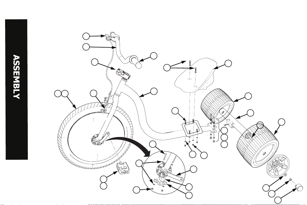
Parts assembly view
5

noitpircseD.oNnoitpircseD.oN
)2x(tloB81emarF1
)4x(rehsaW91metS2
)2x(tuN02rabeldnaH3
tfeL-ladeP12)2x(spirG4
thgiR-ladeP22reveLekarB5
knarC32ekarB6
7 Seat 24 Wheel Retainer (x2)
8 Screw - Long (x2) 25 Wheel Bushing (x4)
)4x(tloB62)4x(trohS-wercS9
)8x(rehsaW72)10x(rehsaW01
)4x(tuN82)4x(tuN11
eriT92emarFraeR21
ebuT03elxA31
)2x(leehW41
15 Washer (x2)
16 Nut (x2)
17 Cap (x2)
Parts assembly List
6
Caution: Check parts list first, stop assembly if any parts missing or defective

Parts Assembly
7
Handlebar Installation
Stem(1) and fork(2) are pre-installed.
The stem (1) is installed upside down for packaging and must be adjusted
before assembly handlebar.Turn the fork so it faces forward.
Make sure that the stem(1) is pointing upward and facing the same direction as
the fork(2) and brake calipers(3) are facing forward. 1
23
AX 2
Steps:
1. Remove Screws (A) and Stem
Clamp Half (5).
2. Place Handlebar (4) centered
into Stem and install Stem
Clamp and Screws hand tight.
3. Position Handlbars so they are
comfortable for the rider.
4. Tighten Screws securely and
evenly.
5
A
4
Note: Please do not
assembly in wrong
direction.

8
Tightening Tests:
Test the tightness of the stem bolts:
Straddle the front wheel and hold it between your legs.
Gently try to turn the front wheel by turning the handlebar.
If the handlebar and stem turn on the fork realign the stem with the wheel and tighten the stem bolts tighter than
before(about 1/4 revolution at a time)
Repeat this test until the stem does not move on the fork.
Test the tightness of the handlebar clamp:
Hold the bicycle stationary.
Gently try to move the ends of the handlebar forward / backward or up / down.
If the handlebar moves loosen the handlebar clamp bolt(s) and relocate the handlebar in correct position.
Tighten the handlebar clamp bolt(s) tighter than before(about 1/4 revolution at a time).
If the handlebar clamp has more than one bolt, tighten the bolts equally.
Repeat this test until the handlebar does not move in the handlebar clamp.
WARNING: Do not over-tighten the bolts. Over-tightening the bolts can damage the steering system and cause
loss of control.
If the handlebar clamp bolt(s) or stem clamp bolts are not tight enough the handlebar can slip in the stem or the
stem can slip on the fork. This can damage the handlebar or stem and cause loss of control.
Parts Assembly
This manual suits for next models
1
Other KMART Bicycle manuals

KMART
KMART 45CM PHANTOM AQUA BIKE User manual

KMART
KMART Mercury User manual

KMART
KMART NEPTUNE BIKE User manual

KMART
KMART 42333753 User manual

KMART
KMART Balance User manual

KMART
KMART 42959885 User manual

KMART
KMART 42959885 User manual

KMART
KMART NEPTUNE User manual

KMART
KMART 43240661 User manual

KMART
KMART 42271840 700C User manual


