Knauer Azura Degasser DG 2.1S User manual

Degasser DG 2.1S
Instructions
Document No. V6880
HPLC

Note: The contents of this user manual apply for the BlueShadow product.
Please submit a request on any article numbers for BlueShadow.

Table of Contents 3
DG 2.1S user manual V6880, version 3.3
Table of Contents
Note: For your own safety, read the manual and always observe the warnings
and safety information on the device and in the manual!
Intended Use. . . . . . . . . . . . . . . . . . . . . . . . . . . . . . . . . . . . . . . . . . . . . . . . . 5
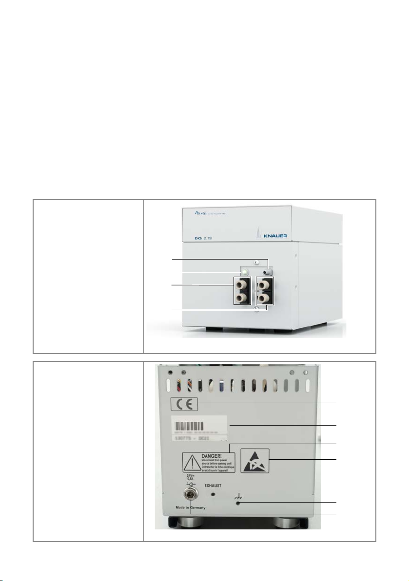
Device Overview . . . . . . . . . . . . . . . . . . . . . . . . . . . . . . . . . . . . . . . . . . . . 5
Features . . . . . . . . . . . . . . . . . . . . . . . . . . . . . . . . . . . . . . . . . . . . . . . . . . 6
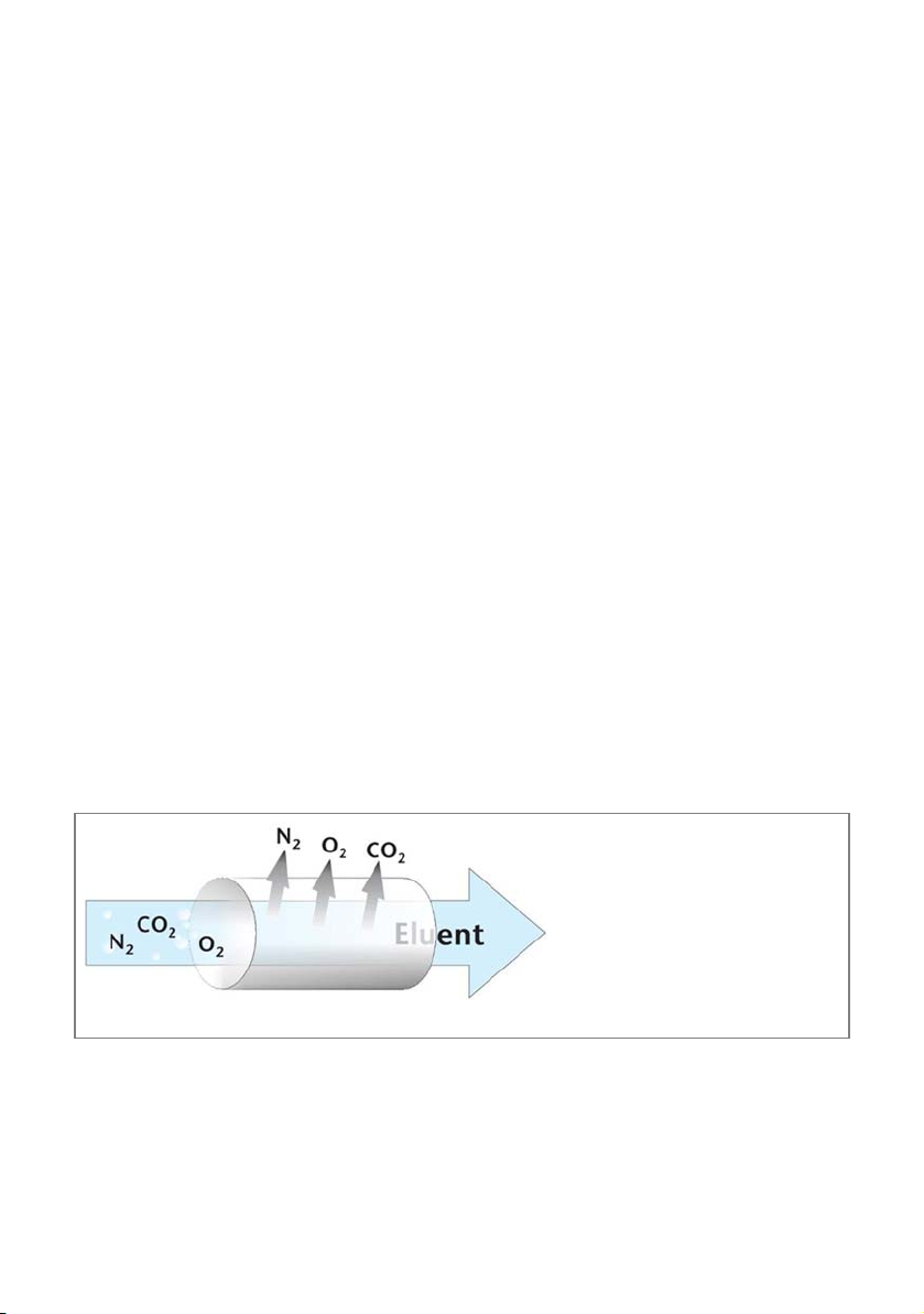
Degassing Principle . . . . . . . . . . . . . . . . . . . . . . . . . . . . . . . . . . . . . . . . . . 6
Eluents . . . . . . . . . . . . . . . . . . . . . . . . . . . . . . . . . . . . . . . . . . . . . . . . . . . 7
Scope of Delivery . . . . . . . . . . . . . . . . . . . . . . . . . . . . . . . . . . . . . . . . . . . . . 8
Safety for the User . . . . . . . . . . . . . . . . . . . . . . . . . . . . . . . . . . . . . . . . . . . . 8
Signal Words . . . . . . . . . . . . . . . . . . . . . . . . . . . . . . . . . . . . . . . . . . . . . . . 9
Decontamination . . . . . . . . . . . . . . . . . . . . . . . . . . . . . . . . . . . . . . . . . . 10
Symbols and Signs . . . . . . . . . . . . . . . . . . . . . . . . . . . . . . . . . . . . . . . . . . . 10
Unpacking and Setup . . . . . . . . . . . . . . . . . . . . . . . . . . . . . . . . . . . . . . . . . 11
Contacting the Technical Support . . . . . . . . . . . . . . . . . . . . . . . . . . . . . . 11
Location Requirements . . . . . . . . . . . . . . . . . . . . . . . . . . . . . . . . . . . . . . 11
Unpacking . . . . . . . . . . . . . . . . . . . . . . . . . . . . . . . . . . . . . . . . . . . . . . . 12
Initial Startup . . . . . . . . . . . . . . . . . . . . . . . . . . . . . . . . . . . . . . . . . . . . . . . 12
Screw Fitting of the Solvent Tube . . . . . . . . . . . . . . . . . . . . . . . . . . . . . . 12
Solvent Tube Connection . . . . . . . . . . . . . . . . . . . . . . . . . . . . . . . . . . . . 12
Connecting Degasser and Pump . . . . . . . . . . . . . . . . . . . . . . . . . . . . . . . 12
Switching On the Degasser . . . . . . . . . . . . . . . . . . . . . . . . . . . . . . . . . . . 13
Purging . . . . . . . . . . . . . . . . . . . . . . . . . . . . . . . . . . . . . . . . . . . . . . . . . . 14
Leak Test . . . . . . . . . . . . . . . . . . . . . . . . . . . . . . . . . . . . . . . . . . . . . . . . . 14
Switching Off the Degasser . . . . . . . . . . . . . . . . . . . . . . . . . . . . . . . . . . . 14
Short-Term Switch-Off . . . . . . . . . . . . . . . . . . . . . . . . . . . . . . . . . . . . 14
Long-Term Switch-Off . . . . . . . . . . . . . . . . . . . . . . . . . . . . . . . . . . . . 15
Troubleshooting . . . . . . . . . . . . . . . . . . . . . . . . . . . . . . . . . . . . . . . . . . . . . 15
Possible Problems and Rectifications . . . . . . . . . . . . . . . . . . . . . . . . . . . . 15
Maintenance and Care . . . . . . . . . . . . . . . . . . . . . . . . . . . . . . . . . . . . . . . . 16
Maintenance Contract . . . . . . . . . . . . . . . . . . . . . . . . . . . . . . . . . . . . . . 16
Cleaning and Caring for the Device . . . . . . . . . . . . . . . . . . . . . . . . . . . . 16
What is to be done if the degasser leaks? . . . . . . . . . . . . . . . . . . . . . . . . 17
Tightening Screw Fittings . . . . . . . . . . . . . . . . . . . . . . . . . . . . . . . . . . . . 17
Preventative Measures . . . . . . . . . . . . . . . . . . . . . . . . . . . . . . . . . . . . . . 17

4TableofContents
DG 2.1S user manual V6880, version 3.3
Technical Data. . . . . . . . . . . . . . . . . . . . . . . . . . . . . . . . . . . . . . . . . . . . . . . 17
Accessories and Spare Parts . . . . . . . . . . . . . . . . . . . . . . . . . . . . . . . . . . . . 18
Legal Information . . . . . . . . . . . . . . . . . . . . . . . . . . . . . . . . . . . . . . . . . . . . 18
Transport Damage . . . . . . . . . . . . . . . . . . . . . . . . . . . . . . . . . . . . . . . . . 18
Warranty Conditions . . . . . . . . . . . . . . . . . . . . . . . . . . . . . . . . . . . . . . . . 18
Declaration of Conformity . . . . . . . . . . . . . . . . . . . . . . . . . . . . . . . . . . . . 19
Disposal . . . . . . . . . . . . . . . . . . . . . . . . . . . . . . . . . . . . . . . . . . . . . . . . . 19
Index . . . . . . . . . . . . . . . . . . . . . . . . . . . . . . . . . . . . . . . . . . . . . . . . . . . . . . 20

Intended Use 5
DG 2.1S user manual V6880, version 3.3
Intended Use
Note: Only use the device for applications that fall within the range of the
intended use. Otherwise, the protective and safety equipment of the device
could fail.
Device Overview
The degasser is a device for degassing eluents. On the front of the device, there
are 2 analytical degasser chambers with inlet and outlet side, one bicolor LED
and the exhaust port. Air and possibly solvent vapors will be pumped out
through the exhaust port. If necessary, it can be combined with a fume hood or
similar extraction devices.
The ports for ground and mains connection are located on the rear side of the
degasser.
Legend
1 Exhaust port
2 LED
3 Outlets
4 Inlets
Fig. 1 Analytical 2-channel degasser Rear view
Legend
1 CE mark
2 Serial number
3 Warning 1
4 Warning 2
5 Ground
6 Mains connection
for power supply
with power switch
Fig. 2 Analytical 2-channel degasser, rear view
2
3
4
1
2
3
4
6
1
5

6 Intended Use
DG 2.1S user manual V6880, version 3.3
Operating range
Gases that have dissolved into the solvent can cause bubbles in pumps and
detectors. Good chromatographic separation therefore requires degassing the
solvent. The analytical 2-channel degasser DG 2.1S is equipped with two degas-
sing chambers and can thus simultaneously degas two solvents.
The device can be used in the following areas:
Biochemistry analyses
Chemical analyses
Food analyses
Pharmaceutical analyses
Environmental analyses
Chiral analyses
The degasser is, e. g., used at universities, research institutions, and routine lab-
oratories.
Features
Reliable and convenient degassing of up to two eluents at the same time.
Teflon AF® allows high gas diffusion rates
Constant performance vacuum pump for high baseline stability
Chamber volumes lower than 0.5 ml, thus fast eluent changes are possible
Very good physical and chemical stability
Degassing Principle
While the solvent flows through the short Teflon AF®tubes, the dissolved gases
are removed from the solvent by means of a vacuum on the other side of the
membrane.
An integrated vacuum pump maintains a constant vacuum.
Structural properties of the Teflon AF®membrane accelerate the degassing
process.
The solvophobic and hydrophobic properties of Teflon AF®reduces the risk
of contamination when exchanging the solvent.
Fig. 3 Degassing principle

Intended Use 7
DG 2.1S user manual V6880, version 3.3
Thanks to the molecular structure of the Teflon AF®membrane, only a very
small surface is required for degassing the solvent. Thus the risk of carryover
during a solvent change is reduced.
The special pump design makes it possible to flush the pump head with a small
blast of air, to remove solvent fumes, which could escape from the vacuum
chamber.
Eluents
Even small quantities of other substances, such as additives, modifiers, or salts
can influence the durability of the materials.
Note: The list of selected solvents was compiled based on research in the perti-
nent literature and is only a recommendation bythe manufacturer. If there is
any doubt, contact the technical support of the manufacturer.
Not suitable eluents
Chlorobenzene
Chloroform
Concentrated acids
Concentrated bases
Eluents containing particles
Halogenated hydrocarbons, e.g.
Freon®
Heptane
Hexane
Less suitable eluents
Methylene chloride
Diluted phosphoric acid
Slightly volatile eluents
Suitable eluents
Acetic acid, glacial
Acetone
Acetonitrile
Buffers
Dimethyl sulfoxide (DMSO)
Ethanol
Ether
Ethyl acetate
Isopropanol
Hexafluorisopropanol
Hydrochloric acid
Hydro fluoro solvents
Perfluorinated eluents, e.g.
Fluorinert® FC-75, FC-40
Perfluorinated polyether, e.g.
Fomblin®
Sodium azide
Tetrahydrofuran (THF)
Toluene
Methanol, anhydrous
Methyl ethyl ketone
Methyl isobutyl ketone
Methyl tert-butyl ether
N,N-Dimethylacetamide
N,N-Dimethylformamide
n-Propyl alcohol
NMP (N-Methyl-2-pyrrolidinone)
Salt
Water

8 Scope of Delivery
DG 2.1S user manual V6880, version 3.3
Scope of Delivery
Note: Only use original parts and accessories made by the manufacturer or a
company authorized by the manufacturer.
Degasser DG 2.1S plus user manual
Power unit, 24 V , 60 W
Accessory kit AZURA small devices'
Accessory kit DG 2.1S
Safety for the User
Professional Group
The user manual addresses persons who are qualified as chemical laboratory
technicians or have completed comparable vocational training.
The following knowledge is required:
Fundamental knowledge of liquid chromatography
Knowledge regarding substances that are suitable only to a limited extent for
use in liquid chromatography
Knowledge regarding the health risks of chemicals
Participation during an installation of a device or a training by the company
KNAUER or an authorized company.
If you do not belong to this or a comparable professional group, you may not
perform the work described in this user manual under any circumstances. In this
case, please contact your superior.
Safety Equipment
When working with the device, take measures according to lab regulations and
wear protective clothing:
Safety glasses with side protection
Protective gloves
Lab coat
What must be taken into account?
All safety instructions in the user manual
The environmental, installation, and connection specifications in the user
manual
National and international regulations pertaining to laboratory work
Original spare parts, tools, and solvents made or recommended by KNAUER
Good Laboratory Practice (GLP)
Accident prevention regulations published by the accident insurance compa-
nies for laboratory work
Filtration of substances under analysis
Use of inline filters

Safety for the User 9
DG 2.1S user manual V6880, version 3.3
Once they have been used, never re-use capillaries in other areas of the HPLC
system.
Only use a given PEEK fitting for one specific port and never re-use it for
other ports. Always install new PEEK fittings on each separate port.
Follow KNAUER or manufacturer's instructions on caring for the columns
More safety-relevant information is listed below:
flammability: Organic solvents are highly flammable. Since capillaries can
detach from their screw fittings and allow solvent to escape, it is prohibited
to have any open flames near the analytical system.
solvent tray: Risk of electrical shock or short circuit if liquids get into the
device's interior. For this reason, place all bottles in a solvent tray.
solvent lines: Install capillaries and tubing in such a way that liquids cannot
get into the interior in case of a leak.
leaks: Regularly check if any system components are leaking.
power cable: Defective power cables are not to be used to connect the
device and the power supply system.
self-ignition point: Only use eluents that have a self-ignition point higher
than 150 °C under normal ambient conditions.
power strip: If several devices are connected to one power strip, always con-
sider the maximum power consumption of each device.
power supply: Only connect devices to voltage sources, whose voltage equals
the device's voltage.
toxicity: Organic eluents are toxic above a certain concentration. Ensure that
work areas are always well-ventilated! Wear protective gloves and safety
glasses when working on the device!
Where is use of the device prohibited?
Never use the system in potentially explosive atmospheres without appropriate
protective equipment. For further information, contact the Technical Support of
KNAUER.
Secure decommissioning
At any time, take the device completely out of operation by either switching off
the power switch or by pulling the power plug.
Opening the Device
The device may be opened by the KNAUER Technical Support or any company
authorized by KNAUER only.
Signal Words
Possible dangers related to the device are divided into personal and material
damage in this user manual.
Lethal injuries will occur.

10 Symbols and Signs
DG 2.1S user manual V6880, version 3.3
Serious or moderate injuries can occur.
Minor injuries can occur.
Device defects can occur.
Decontamination
Contamination of devices with toxic, infectious or radioactive substances poses
a hazard for all persons during operation, repair, sale, and disposal of a device.
Life-threatening injuries
Health danger if getting in contact with toxic, infectious or radio-active sub-
stances.
Before disposing of the device or sending it away for repair, you are required
to decontaminate the device in a technically correct manner.
All contaminated devices must be properly decontaminated by a specialist com-
pany or the operating company before they can be recommissioned, repaired,
sold, or disposed of. All materials or fluids used for decontamination must be
collected separately and disposed of properly.
Decontaminatin Report
Devices without a completed Decontamination Report will not be repaired. If
you would like to return a device to KNAUER, make sure to enclose a completed
Decontamination Report with the device: http://www.knauer.net/en/down-
loads/service.html
Symbols and Signs
The following table explains those symbols and labels which are used on the
device, in the software or in the manual:
Symbol Explanation
Electrostatic-discharge hazard.

Unpacking and Setup 11
DG 2.1S user manual V6880, version 3.3
Unpacking and Setup
Contacting the Technical Support
You have various options to contact the Technical Support:
Phone: +49 30 809727-0
Fax: +49 30 8015010
E-mail: [email protected]
You can make your requests in English and German.
Location Requirements
Requirements
The location for the device must meet the following requirements:
Device defect
The device overheats at exposure to sunlight and insufficient air circulation.
Device failures are very likely.
Set up the device in such a way that it is protected against exposure to direct
sunlight.
Keep at least 15 cm clear at the rear and 5–10 cm at each side for air circula-
tion.
General warning sign that moderate injuries or device
defects can occur
Device fulfills the requirements of the Conformité
Européenne, which is confirmed by the Declaration of
Conformity.
Weight 2.3 kg
Dimensions 121 × 138 × 190 mm (Width × Height × Depth)
Power supply 85–265 V
Air humidity <90%,non-condensing
Temperature 4-40 °C,39.2-104 °F

12 Initial Startup
DG 2.1S user manual V6880, version 3.3
Unpacking
Store all packing materials. Packing list should be kept for repeat orders.
Tools
Utility knife
Procedure
1. Check for damages caused during transportation. In case you notice any
damage, contact the technical support and the forwarder company.
2. Setup the delivery so the label is in the correct position. Using the utility
knife, cut the adhesive tape. Open the delivery.
3. Remove the foam insert. Take out the accessories kit and the manual.
4. Open the accessories kit and take out all accessories. Check the scope of
delivery. In case any parts are missing, contact the technical support.
5. Grip the device at its side panels and lift it out of the packaging.
6. Remove the foam inserts from the device.
7. Check for damages caused during transportation. In case you notice any
damage, contact the technical support.
8. Set-up the device in its location.
Initial Startup
Screw Fitting of the Solvent Tube
Make sure that the tapered side of the seal ring 1faces the screw fitting 2of
the solvent tube.
Solvent Tube Connection
Appropriate solvent tubes are included in the device accessories.
Make sure that the tube has a straight ending.
Only tighten screw fittings by hand.
Use the supplied blind fittings to seal off all unused inlets and outlets.
Connecting Degasser and Pump
Each degassing chamber features an inlet and an outlet.
Fig. 4 Screw fitting of the solvent tube
12

Initial Startup 13
DG 2.1S user manual V6880, version 3.3
Device defect
Very high pressures can damage the degasser membrane. The membrane can
withstand a maximum pressure of 7 bar.
Never connect the degasser to the pump outlet.
Procedure
1. Connection of the chambers in the direction of the arrow.
2. Remove the blind fittings from the degassing chamber inlets and outlets that
are to be used. Keep the filler caps.
3. Unused in and outlets have to be closed with blind fittings to prevent con-
tamination of the disconnected chambers.
4. The inlets of the degasser chambers are connected to the solvent containers
by means of Teflon tubes.
5. Teflon tubes are also connected to the outlets of the degassing chambers,
with screw fittings and seal rings. These tubes are then connected to the
respective pump.
Switching On the Degasser
Requirements
All lines have been connected correctly.
Unused degasser chambers have been sealed off with blind fittings.
Device defect
Changes of the environmental temperature cause condensation inside the
device.
Allow device to acclimate for 3 h, before connecting to power supply and
taking into operation.
Note: Purge the degasser when changing solvents
Note: Regularly check the capillaries for leaks.
Procedure
1. Switch off the power supply.
2. Connect device with power supply
3. Connect the power supply of the device to the mains.
4. Switch on the power supply. During the start procedure, the LED flashes yel-
low for approx. 30 seconds. After the specified vacuum value has been
reached, the LED lights up green permanently. The device is now ready for
operation.

14 Initial Startup
DG 2.1S user manual V6880, version 3.3
5. Switch on the HPLC pump.
When you switch off the HPLC pump, also switch off the degasser.
Purging
Flush the degasser and the connecting tubes with the appropriate solvent prior
to use. Thanks to the low chamber volume, only small amounts of the solvents
are needed for flushing.
Prerequisite
The degasser is connected to the pump.
Note: Prior to a solvent change in the degasser, purge with a liquid in which
both solvents are soluble.
Procedure
1. Configure the pump: Flow rate 2 ml/min.
2. Start the pump and flush for 1 to 2 minutes.
Leak Test
The vacuum is continuously checked by means of a built-in microprocessor and
the pump output adjusted. Thus it is possible to detect leaks.
Procedure in the event of a detected leak
If a leak is detected, the microprocessor of the degasser automatically
increases the pump speed to maintain the vacuum. If the vacuum still falls
below the target value, the yellow LED flashes.
If it is not possible to achieve the required vacuum within 30 minutes by
means of the increased pump output, the LED lights up yellow at the degas-
ser to indicate that there is possibly a leak in the system.
The degasser will be switched off automatically.
Switching Off the Degasser
Here a differentiation is made between short-term and long-term switch-off.
Note: To separate the degasser from the mains, remove the switched-mode
power supply from the rear of the device.
Short-Term Switch-Off
Note: Damage to the degasser that results from using buffer-containing sol-
vents are not covered by the warranty.
Procedure
1. Remove critical solvent from the degassing chambers and other system com-
ponents by purging with for example isopropanol (2-propanol) .
2. Subsequently purge with water.

Troubleshooting 15
DG 2.1S user manual V6880, version 3.3
3. If the degasser is switched off for several days (e.g. over the weekend), purge
the device with isopropanol prior to ending operation.
4. Switch off the degasser at the power supply.
Long-Term Switch-Off
Procedure
1. Remove critical solvent from the degassing chambers and other system com-
ponents by purging with a suitable solvent.
2. First purge the degasser with water and subsequently with isopropanol.
3. Switch off the degasser and remove the connection tubes to the degasser.
4. The degasser chambers can be dried by means of laboratory gas.
5. Seal all inlets and outlets of the degasser with blind fittings and subsequently
store the device at a safe and dry location.
6. Prior to the reuse of the degasser, purge the device briefly with the solvent
which will be used afterwards.
Troubleshooting
First measures
1. Check all cabling.
2. Check all screw fittings.
3. Check whether air has gotten into the supply lines.
4. Check device for leaks.
Further measures:
Check errors against error list
Contact the technical support hotline of the manufacturer
Possible Problems and Rectifications
Problem Cause Solution
The device is on, but the
LED is not light and the
device is not energized.
Power supply or plug
is not plugged
Fuse blown
Power supply is defec-
tive
Contact the service
department.

16 Maintenance and Care
Further measures
Inform the Technical Support of the manufacturer.
Maintenance and Care
Proper maintenance of your HPLC device will ensure successful analyses and
reproducible results.
Maintenance Contract
The following maintenance work on the device may only be performed by the
manufacturer or a company authorized by the manufacturer and is covered by
a separate maintenance contract:
Opening the device
Removing the hood or the side panels.
Cleaning and Caring for the Device
All smooth surfaces of the device can be cleaned with a mild, commercially avai-
lable cleaning solution, or with isopropanol.
DG 2.1S user manual V6880, version 3.3
The device is running
but you can not/hardly
hear the pump.
At low rotational speeds,
the pump can hardly be
heard, although the vac-
uum is good and the
degassing process is tak-
ing place.
Compare the baseline of
non-degassed ethanol at
251 nm with the base-
line of degassed etha-
nol. If the degasser is
working properly, the
noise of the baseline of
the non-degassed etha-
nol should be signifi-
cantly higher.
Air bubbles occur in the
solvent tubes of the
degasser outlet.
Loose or damaged screw
fittings
Check the inlet and out-
let fittings. Replace old
fittings, if necessary.
No solvent flow Air in the degasser cham-
bers
Purge degasser cham-
bers
If a buffer solution is left
in the degasser for an
extended period, it can
cause clogging in the
degasser.
Use another degasser
chamber. Carefully let
water flow into the
clogged degasser cham-
ber to dissolve the buf-
fer. If this does not help,
contact the service
department.
Problem Cause Solution

Technical Data 17
DG 2.1S user manual V6880, version 3.3
Device defect
Intruding liquids can cause damage to the device.
Place solvent bottles next to the device or in a solvent tray.
Moisten the cleaning cloth only slightly.
What is to be done if the degasser leaks?
If the degasser leaks, solvent can reach the motor and from there reach the
degasser exhaust and flow out. In this case, the automatic pump control will
switch the device off.
Inform the Technical Support of KNAUER.
Tightening Screw Fittings
1. If the screw fitting of the solvent tube is untight, carefully tighten the screw
fitting.
2. If it still leaks, loosen and check the screw fitting.
3. If no damage or deformation is visible at the seal ring and at the screw fit-
ting, repeat step 1.
4. If it still leaks, replace the screw fitting and seal ring.
Preventative Measures
To ensure that the degasser can constantly run at maximum capacity, pay
attention to the following:
Only use ultrapure solvent as mobile phase. If water is used as solvent, it also
has to fulfill this standard or be filtered and deionized.
Filter all solvents to prevent clogging.
To dry the degasser, only use ultrapure gas.
Observe the information on switching off the degasser.
Technical Data
Channels 2
Maximum flow rate 10 ml/min
Degassing method gas permeation through a fluoropolymer membrane
Dead volume approx. 285 μl per channel
Pressure decline 1.37 mm (Hg/ml/min)
Max. pressure stability 7 bar
Wetted materials PEEK, glass-filled PTFE, Teflon AF®
Display 1 LED
Dimensions 121 x 138 x 190 mm

18 Accessories and Spare Parts
DG 2.1S user manual V6880, version 3.3
Accessories and Spare Parts
For repeat orders of spare parts please contact the Technical Support of the
manufacturer or conform to the packing list which is enclosed when the device
is delivered.
Note: For repeat orders of spare parts use the enclosed packing list. Contact the
Technical Support in case there are any questions on spare parts or accessories.
Legal Information
Transport Damage
The packaging of our devices provides the best possible protection against
transport damage. Check the devices for signs of transport damage. In case you
notice damages, contact the Technical Support and the forwarder company
within three workdays.
Warranty Conditions
The factory warranty for the device is stipulated by contract. During the war-
ranty period, any components with material or design-related defects will be
replaced or repaired by the manufacturer free of charge. Please connect to our
website for further information on terms and conditions.
All warranty claims shall expire in the event that any unauthorized changes are
made to the device. This warranty also excludes the following:
accidental or willful damage
damage or errors caused by third parties that are not contractually related to
the manufacturer at the time the damage occurs
wear parts, fuses, glass parts, columns, light sources, cuvettes and other opti-
cal components
damage caused by negligence or improper operation of the device and dam-
age caused by clogged capillary
packaging and transport damage
Weight 2.3 kg
Power supply 85–265 V, 50–60 Hz, 20 W
Ambient conditions temperature range: 4–40°C; 39.2–104 F
air humidity: below 90 %, non-condensing
Name Order number
Degasser DG 2.1S AZE02
Accessory kit AZURA small devices FZA01
Accessory kit DG 2.1S FZE02
User manual V6880

Legal Information 19
In theevent of device malfunctions, directly contact the manufacturer.
KNAUER Wissenschaftliche Geräte GmbH
Hegauer Weg 38
14163 Berlin, Germany
Phone:+49 30 809727-111
Telefax:+49 30 8015010
e-mail:[email protected]
Internet:www.knauer.net
Declaration of Conformity
The Declaration of Conformity is part of the delivery and accompanies the prod-
uct as a separate document.
Disposal
Hand in old devices or disassembled old components at a certified waste facility,
where they will be disposed of properly.
AVV Marking in Germany
According to the German "Abfallverzeichnisverordnung" (AVV) (January, 2001),
old devices manufactured by KNAUER are marked as waste electrical and elec-
tronic equipment: 160214.
WEEE Registration
KNAUER as a company is registered by the WEEE number DE 34642789 in the
German "Elektroaltgeräteregister" (EAR). The number belongs to category 8 and
9, which, among others, comprise laboratory equipment.
All distributors and importers are responsible for the disposal of old devices, as
defined by the WEEE directive. End-users can send their old devices manufac-
tured by KNAUER back to the distributor, the importer, or the company free of
charge, but would be charged for the disposal.
Solvents and Other Operating Materials
All solvents and other operating materials must be collected separately and dis-
posed of properly.
All wetted components of a device, e. g. flow cells of detectors or pump heads
and pressure sensors for pumps, have to be flushed first with isopropanol and
then with water before being maintained, disassembled or disposed.
DG 2.1S user manual V6880, version 3.3

20 Index
DG 2.1S user manual V6880, version 3.3
Index
A
Accessories 8
Acids 7
Additives 7
Ambient conditions 18
AVV marking 19
C
contamination 10
D
decontamination 10
Degasser
Front view 5
Degassing principle 6
disposal 10
E
Eluent 6
Environmental protection 19
F
Flushing the device
Flushing the degasser 14
I
Installation location, see location 11
L
leak 9
Leak test 14
Leakage 17
Location 11
Long-term switch-off 15
M
Modifiers 7
O
Order numbers 18
P
power cable 9
power strip 9
power supply 9
professional group 8
R
repair 10
S
safety equipment 8
Salts 7
Screw fittings
tightening 17
Short-term switch-off 14
solvent
flammability 9
line 9
self-ignition point 9
tray 9
Solvent exchange 14
Solvent tube
Screw fitting 12
Spare Parts 8
Spare parts 18
Switch-off 14
Switch-on 13
T
Technical Support 11
transport damage 18
W
warranty 18
Table of contents
Other Knauer Analytical Instrument manuals
Popular Analytical Instrument manuals by other brands

Aber
Aber FUTURA neo user manual

SICK
SICK Master Data Analyzer Vision operating instructions

YOKOGAWA
YOKOGAWA ZR202G user manual

Toya
Toya Vorel 81791 Operating instruction

Teledyne Analytical Instruments
Teledyne Analytical Instruments 3110XL operating instructions

Bante Instruments
Bante Instruments MS400C user manual

ESCO Technologies
ESCO Technologies ETS-Lindgren HI-6122 user manual

Rohde & Schwarz
Rohde & Schwarz UMS100 System manual

Responsive Respiratory
Responsive Respiratory Respond O2 Operation manual

General Pipe Cleaners
General Pipe Cleaners Gen-Eye Prism 2.0 operating instructions

Vividia
Vividia Ablescope FC-8050i manual

Macherey-Nagel
Macherey-Nagel NANOCOLOR 500 D manual