INSTRUCTIONS –EMGUKIT1
These instructions should be read carefully and retained after installation by the end-user for future reference
and maintenance.
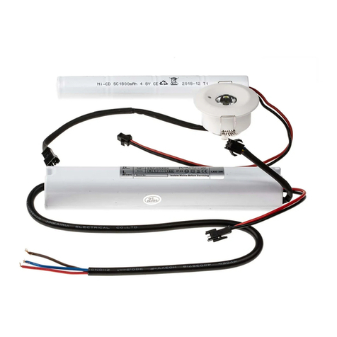
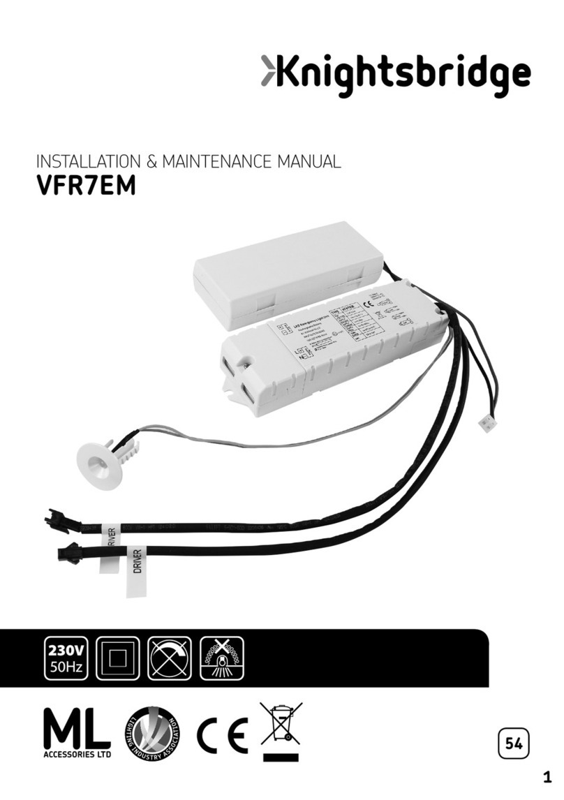
These instructions should be used to aid the installation of the following product:
EMGUKIT1
SAFETY
•This product must be installed in accordance with the latest edition of the IEE Wiring Regulations
(BS7671) and current Building Regulations. If in any doubt, consult a qualified electrician
•Please isolate mains prior to installation or maintenance
•Please note the IP (Ingress Protection) rating of this product when deciding the location for installation
•Do not overload this accessory or subject it to conditions outside its rating
•This product is Class II
•This product is IP20 rated
INSTALLATION
•Provide power to the required point of installation
•Cut a suitable hole in the mounting surface as per the cut-out details of the downlight or fitting to be
used with this emergency kit, ensuring not to infringe with any joists, gas/ water pipes or electrical
cables
Note: This emergency kit requires a minimum 55mm cut-out
•Wire for switched-maintained operation by connecting to the Live (Brown), Switched Live (Red) and
Neutral (Blue) or non-maintained mode by connecting to the Live (Brown) and Neutral (Blue), see
Fig. 1. Remove the link between LS and L if not required
Fig. 1
•Secure the mains cable under the cable clamp and refit the connection box cover
•Ensure the battery is connected via the plug-in connector
•Mark the location of the LED indicator holder and drill an 18mm hole ensuring it does not infringe with
any joists, gas, water pipes or electrical cables
•Switch on and check for correct operation, ensuring the green indicator LED is illuminated
•We recommend, on commissioning the installation, a minimum charge period of 24 hours before
carrying out an emergency duration test
•If the batteries have been left in a discharged state for an extended period, we recommend that one or
more charge and discharge cycles are completed which should help to restore the battery capacity
WARNING
Fig. 1
Note: This emergency kit requires a minimum 55mm cut-out
• Wire for switched-maintained operation by connecting to the Live (Brown), Switched Live (Red) and Neutral
(Blue) or non-maintained mode by connecting to the Live (Brown) and Neutral (Blue) (see Fig. 1). Remove
the link between LS and L if not required
• Secure the mains cable under the cable clamp and refit the connection box cover
• Ensure the battery is connected via the plug-in connector
• Mark the location of the LED indicator holder and drill an 18mm hole ensuring it does not infringe with any
joists, gas/water pipes or electrical cables
• Connect a GU10 lamp to the lamp holder
• Switch on and check for correct operation, ensuring the green indicator LED is illuminated
• We recommend, on commissioning the installation, a minimum charge period of 24 hours before carrying out
an emergency duration test
• If the batteries have been left in a discharged state for an extended period, we recommend that one or more
charge and discharge cycles are completed which should help to restore the battery capacity
