•Replace the terminal cover and tighten the screws
•Plug the sensor lead into the socket on the power module
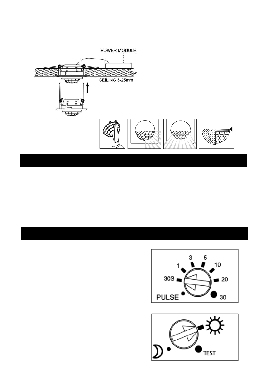
•Insert the power module into the cut-out ensuring it is not covered by insulation
•Fold the springs upwards and fit the sensor head into the cut-out (see Fig 3)
Fig 3
•Using the blanking lens provided, cut as required and fit onto the front of the sensor head - the blanking lens is
used to limit the detection angle of the sensor when nuisance triggering and interference is present (see Fig 4)
Fig 4
Test mode: For initial setup of the sensor, turn the time control fully anti-clockwise to the minimum position and the lux
control fully clockwise to the test position
After the sensor has been switched on it will take up to 30 seconds to enter into automatic mode
Once in automatic mode, walk test the PIR by moving in front of the sensor at various positions of the required field of
view, checking that the luminaire is activated at each point
After the initial setup and walk test have been completed, adjust the time and lux setting to the desired levels
•Replace the terminal cover and tighten the screws
•Plug the sensor lead into the socket on the power module
•Insert the power module into the cut-out ensuring it is not covered by insulation
•Fold the springs upwards and fit the sensor head into the cut-out (see Fig 3)
Fig 3
•Using the blanking lens provided, cut as required and fit onto the front of the sensor head - the blanking lens is
used to limit the detection angle of the sensor when nuisance triggering and interference is present (see Fig 4)
Fig 4
Test mode: For initial setup of the sensor, turn the time control fully anti-clockwise to the minimum position and the lux
control fully clockwise to the test position
After the sensor has been switched on it will take up to 30 seconds to enter into automatic mode
Once in automatic mode, walk test the PIR by moving in front of the sensor at various positions of the required field of
view, checking that the luminaire is activated at each point
After the initial setup and walk test have been completed, adjust the time and lux setting to the desired levels
• Replace the terminal cover and tighten the screws
• Plug the sensor lead into the socket on the power module
• Insert the power module into the cut-out ensuring it is not covered by insulation
• Fold the springs upwards and fit the sensor head into the cut-out (see Fig 3)
• Using the blanking lens provided, cut
as required and fit onto the front of
the sensor head - the blanking lens is
used to limit the detection angle of the
sensor when nuisance triggering and
interference is present (see Fig 4)
For initial setup of the sensor, turn the time control fully anti-clockwise to the minimum position
and the lux control fully clockwise to the test position
After the sensor has been switched on it will take up to 30 seconds to enter into automatic mode
Once in automatic mode, walk test the PIR by moving in front of the sensor at various positions of
the required field of view, checking that the luminaire is activated at each point
After the initial setup and walk test have been completed, adjust the time and lux setting to the
desired levels
3
SENSOR SETUP
TEST MODE
To access the sensor control dials, pull down on the
inner bezel marked “open” with a small flat-head
screwdriver screwdriver to reveal the controls
Note: When making adjustments to the PIR settings
ensure the sensor is powered down
Time control: 30 seconds – 30 minutes. Turn the
dial clockwise to increase the length of time the
luminaire will remain on. PULSE mode sends a
signal to the luminaire 1 second on, 9 seconds off
Lux control: 5 lux – 1000 lux. This setting will adjust
the ambient light level the sensor will operate at.
If you require the luminaire to operate in brighter
conditions turn the dial clockwise - dusk is
approximately at the 12 o’clock position
SENSOR SETUP
To access the sensor control dials, pull down on the inner bezel marked “open” with a small flat bladed screwdriver to
reveal the controls
Note: When making adjustments to the PIR settings ensure the sensor is powered down
Time control: 30 sec –30 min. Turn the dial clockwise to increase the length of time the luminaire will remain on. PULSE
mode sends a signal to the luminaire 1 second on, 9 seconds off
Lux control: 5 Lux –1000 Lux. This setting will adjust the ambient light level the sensor will operate at. If you require the
luminaire to operate in brighter conditions turn the dial clockwise - dusk is approximately at the 12 o’clock position
Detection control: 0.5 meter radius –4 meter radius. Set to the maximum position with the sensor mounted at 3 meters,
the sensor has a detection radius of approximately 4 meters
Set to the minimum position with the sensor mounted at 3 meters, the sensor has a detection radius of approximately 0.5
meters
Fig 3
Fig 4