Kobelt 5040-SA Instruction Manual

KOBELT MANUFACTURING CO. LTD MNL-5040-SA.docx (rev B) 1
5040-SA CALIPER BRAKE
SPRING / AIR VERSION
Owner’s Operation, Installation &
Maintenance Manual

KOBELT MANUFACTURING CO. LTD MNL-5040-SA.docx (rev B) 2
Table of Contents
1Introduction ..................................................................................................................4
1.1 Contact Information......................................................................................................4
1.2 Safety Information ........................................................................................................4
1.2.1 Safety Instructions ....................................................................................................4
1.2.2 Hazards .....................................................................................................................5
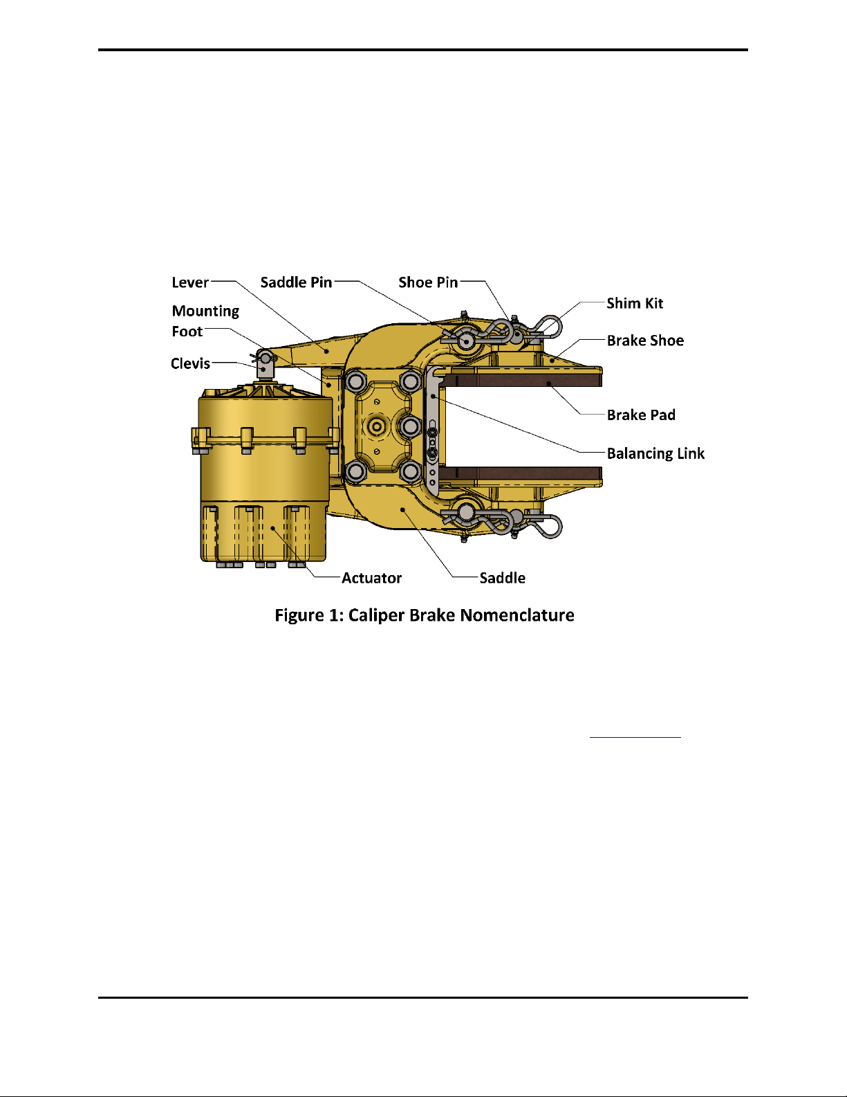
1.3 Product Description.......................................................................................................6
1.3.1 Overview...................................................................................................................6
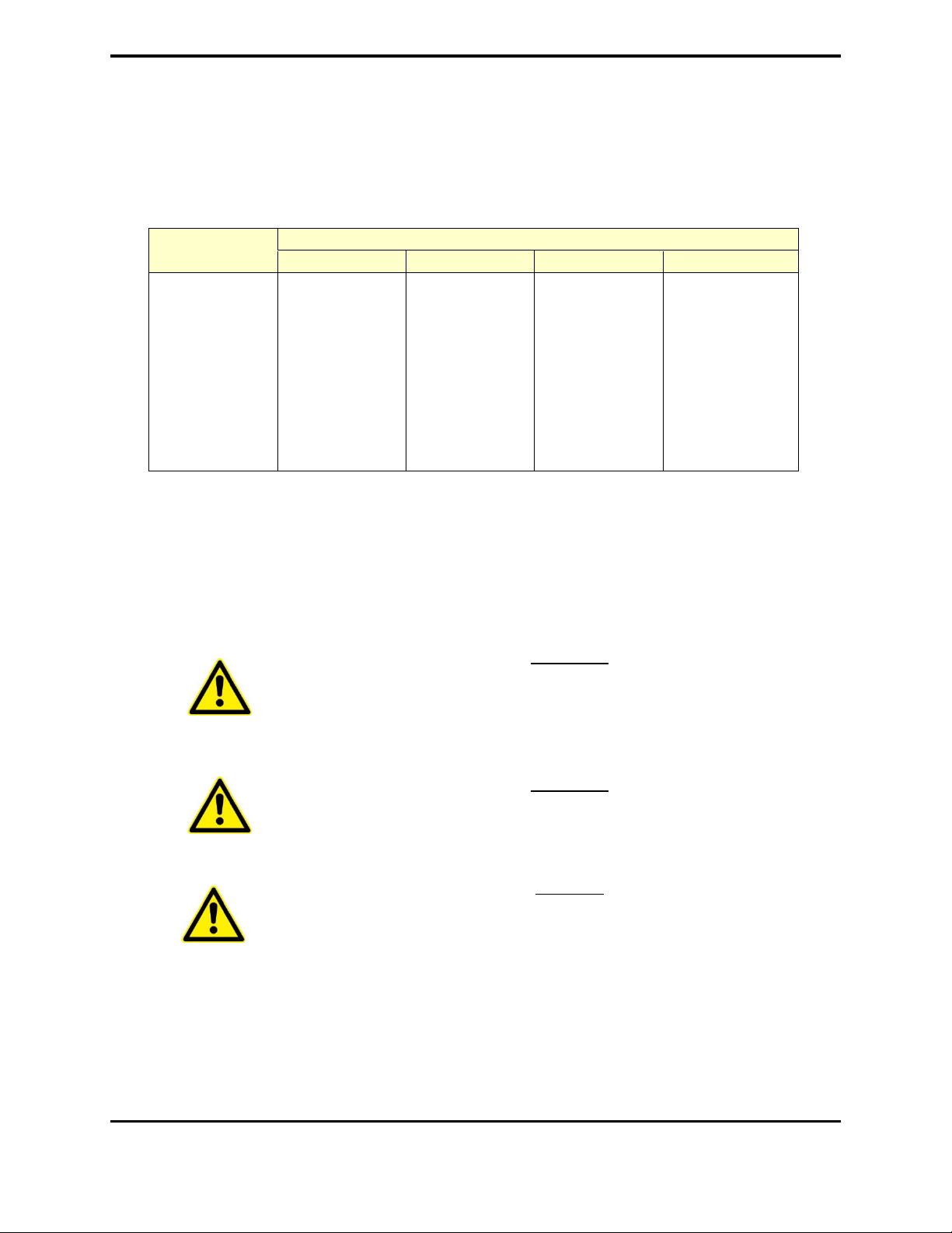
1.4 Technical Data...............................................................................................................6
2Installation ....................................................................................................................7
2.1 Preparation ...................................................................................................................7
2.2 Brake Discs ....................................................................................................................7
2.3 Caliper brakes................................................................................................................9
2.3.1 Mechanical................................................................................................................9
2.3.2 Piping ........................................................................................................................9
2.3.3 Instrumentation......................................................................................................10
3Commissioning ............................................................................................................11
3.1 Flushing.......................................................................................................................11
3.2 Air Gap ........................................................................................................................11
3.3 Function Test...............................................................................................................11
3.4 Burnishing ...................................................................................................................11
3.5 Torque Test .................................................................................................................12
4Operation....................................................................................................................13
4.1 Functional Requirements ............................................................................................13
4.1.1 Pressure Supply.......................................................................................................13
4.1.2 Control ....................................................................................................................14
4.2 Service Limits ..............................................................................................................14
4.2.1 Disc Temperature....................................................................................................14
4.2.2 Ambient Temperature ............................................................................................14
4.2.3 Pressure ..................................................................................................................14
4.2.4 Disc speed...............................................................................................................14
5Maintenance ...............................................................................................................15
5.1 Preventative Maintenance..........................................................................................15
5.2 Inspection....................................................................................................................15
5.2.1 Pad Wear ................................................................................................................15
5.2.2 Seals........................................................................................................................16
5.2.3 Actuator Test ..........................................................................................................16
5.2.4 Pin Wear .................................................................................................................16
5.2.5 Brake Disc ...............................................................................................................16

KOBELT MANUFACTURING CO. LTD MNL-5040-SA.docx (rev B) 3
5.2.6 NDE Structural Components ...................................................................................17
5.3 Service.........................................................................................................................19
5.3.1 Lubrication..............................................................................................................19
5.3.2 Stroke Adjustment ..................................................................................................19
5.3.3 Spring Actuators......................................................................................................19
5.3.4 Brake Linings...........................................................................................................20
5.4 Recommended Spares.................................................................................................20
6Warranty.....................................................................................................................21
7Appendix A: Technical Drawings...................................................................................22
8Appendix B: Parts List Drawings ...................................................................................23

KOBELT MANUFACTURING CO. LTD MNL-5040-SA.docx (rev B) 4
1INTRODUCTION
1.1 CONTACT INFORMATION
Kobelt Manufacturing Co LTD.
8238 129TH Street
Surrey, British Columbia
Canada, V3W 0A6
Sales Tel:
Fax:
Email:
Website:
604-572-3935
604-590-8313
www.kobelt.com
For further instructions, please contact our distributors or visit our website.
1.2 SAFETY INFORMATION
1.2.1 Safety Instructions
Notice to Installer:
Disregarding the following safety measures can result in an accident causing severe injury to
personnel and damage to material assets:
•Only use the product as directed in this manual.
•Never put the product into service if there is evidence of visible damage.
•Never put the product into service before fully completing installation and
commissioning.
•Do not carry out any modifications to the product.
•Only use authentic Kobelt spare parts.
•Observe all local regulations, directives and laws during the installation of this product.
•All installation, commissioning and maintenance work must only be conducted by
qualified personnel. (For the purpose of this manual, qualified personnel are persons
who are familiar with the assembly, installation, commissioning, and operation of the
product and who have the qualifications necessary for their occupation.)
•Observe all specifications in this manual. If these guidelines are not followed and
damage occurs, the warranty will be voided.

KOBELT MANUFACTURING CO. LTD MNL-5040-SA.docx (rev B) 5
1.2.2 Hazards
Throughout this publication, Warnings and Cautions accompanied by the International Hazard
Symbol is used to alert the user to special instructions concerning a particular service or
operation that may be hazardous if performed incorrectly or carelessly.
EQUIPMENT STARTS AUTOMATICALLY
Brake systems frequently are controlled remotely and may
activate suddenly causing bodily harm. Ensure all power
sources are locked out prior to performing work.
BRAKE ACTUATORS CONTAIN COMPRESSED SPRINGS
The brake actuators contain springs that are under compression
even when the brakes are not pressurized. The springs will
release suddenly if disassembled incorrectly posing a risk of
serious injury or death. Do not attempt to disassemble the
actuators without clear work instructions and training.
PINCH POINTS
Brakes contain numerous pinch points which can cause serious
injury. Ensure all power sources are locked out prior to
performing work.
HIGH PRESSURE FLUIDS
Kobelt lever brakes use high pressure hydraulics or air. Ensure
all pressure is exhausted and the pressure source locked out
prior to performing work.
HOT SURFACES
Disc brakes are capable of making the surfaces of the brake disc
dangerously hot when burnishing or during braking events.
Ensure the disc is adequately guarded to prevent inadvertent
contact with the disc.
AIRBORNE DUST
Brake linings contain fibers that may become airborne during
cutting or sanding operations. Over exposure to these dusts
should be considered hazardous. Use NIOSH approved
respirators when working with brake linings. Request a MSDS
for further information.

KOBELT MANUFACTURING CO. LTD MNL-5040-SA.docx (rev B) 6
1.3 PRODUCT DESCRIPTION
1.3.1 Overview
The diagram below shows a typical Kobelt caliper brake with all the major components
identified. All of the Kobelt caliper brakes can be fitted with either air applied, hydraulic
applied, spring applied with air released or spring applied with hydraulic released actuators
depending on the required service.
1.4 TECHNICAL DATA
For technical data and specifications refer to the relevant data sheets from www.kobelt.com or the
technical drawings in Appendix A if provided.

KOBELT MANUFACTURING CO. LTD MNL-5040-SA.docx (rev B) 7
2INSTALLATION
2.1 PREPARATION
The foundation plate to support the brake caliper must be designed to withstand the maximum
braking forces generated by the brake caliper. The foundation must also be flat to ISO tolerance
grade IT8 and square to the brake disc. See Appendix A for key installation dimensions. The
brake pedestal must be designed to allow the mounting bolts to be inserted from underneath.
The rotating element should have bearings sufficient to carry the weight of the disc and also
resist the additional stress when the disc brake is applied.
The spigot that centers the brake disc must not be designed in such a way that it impedes the
thermal expansion of the disc.
Actuator ports are plugged to prevent contamination of the seals. Remove the plugs prior to
connection to the piping.
Brake discs are shipped with a light rust inhibitor applied to the surfaces. Remove the rust
inhibitor using solvent and a cloth prior to installation.
Any guarding around the brakes must provide enough room to allow full extension of the bake
actuators plus full pad wear adjustment.
2.2 BRAKE DISCS
The brake disc must be installed onto the rotating element before installing the caliper. Brake
discs must meet the following requirements:
Axial Run out: IT9 (TIR) (1)
Radial Run out: IT11 (TIR) (1)
Flatness: IT9 (2)
Pilot fit: H9/f8
Surface Finish: 63 micro inches RMS
Surface Hardness: Light Duty (3) HB135 minimum
Heavy Duty (4) HB235 minimum
(1) International tolerance class. Allowable run out is proportional disc O.D.
(2) Allowable deviation from flatness is proportional to the shoe width
(3) Parking brakes and emergency brakes with stopping times of 10 seconds or less are
considered light duty.
(4) Ventilated discs are exempted from this requirement
To achieve the run out tolerance the mounting face on the rotating element must be machined
flat. Excessive run-out of the disc could cause premature wear of the linings, caliper pins, lever
journals as well as the actuators.
The disc mounting bolts used must be of a suitable size and grade to safely resist the brake
torque plus the stresses induced from thermal expansion of the disc. For high temperature disc

KOBELT MANUFACTURING CO. LTD MNL-5040-SA.docx (rev B) 8
applications, the holes for the mounting bolts must be machined oversized to allow the disc to
expand during operation. Ensure that adequate washers are used to bridge the gap between
the bolt and bolt hole.
MOUNTING BOLT RADIAL CLEARANCE
Disc Bolt Circle
(inches)
Maximum Disc Temperature, (°F)
400
500
600
700
40
0.043
0.056
0.069
0.082
45
0.049
0.063
0.078
0.092
50
0.054
0.070
0.086
0.103
55
0.059
0.077
0.095
0.113
60
0.065
0.084
0.104
0.123
65
0.070
0.091
0.112
0.134
70
0.076
0.098
0.121
0.144
75
0.081
0.105
0.130
0.154
80
0.086
0.112
0.138
0.164
To reduce the size of the mounting bolt clearance hole it is recommended to offset the bolt
circle on the brake disc inwards the required amount for radial clearance. The end result is the
brake disc will have a slightly smaller bolt circle than the hub and the required radial clearance
will be on the side where it is needed.
WARNI
WARNING!
Do not use fitted bolts for installing brake discs. The bolt holes must
be over sized to permit uninhibited expansion.
WARNING!
Do not secure a brake disc to a rotating element by welding.
WARNING
Do not paint the cooling fins of a ventilated disc. The cooling
efficiency will be compromised and overheating may result.
If the disc was damaged during installation with nicks or welding marks, remove the defects
before putting into service.
For cases where a disc guard or some protective cover is required for a ventilated disc ensure
that the guard does not compromise the performance. An improperly designed cover or shield

KOBELT MANUFACTURING CO. LTD MNL-5040-SA.docx (rev B) 9
may cause air recirculation through the disc or radiant heat reflection, which could result in the
disc overheating. The cooling air pumped through the disc must be exhausted away from the
outer diameter of the disc to allow fresh, cool air to enter the inner vent opening of the disc.
2.3 CALIPER BRAKES
2.3.1 Mechanical
Perform the following steps to properly install a caliper brake:
1. Ensure that the brake has been manually opened (see section 3.1).
2. Lower the brake onto the brake pedestal and center over the mounting holes.
3. Using feeler gauges to ensure that the brake air gap is equal on both sides of the disc.
WARNING!
Ensure the caliper is centered. The balancing link will be subjected
to excessive stresses that will damage it.
4. Position the brake so that the outer radius of the brake shoe is in full contact with the
Disc. Do not move the brake too close as enough radial distance must be provided to
allow for disc expansion without causing interference between the outer circumference
of the disc and the inner caliper frame.
5. Manually apply the brake onto the disc. The brake shoes will naturally align with the disc.
6. Probe under the brake base with feeler gauges to determine the shimming requirement.
7. Manually release the brake again and lift the brake up approximately two inches.
8. Insert the shims determined from step 6. Use ANSI shims that straddle the mounting
bolts.
9. Insert the mounting bolts from underneath the pedestal using appropriate flat washers.
The nut must be on top of the brake foot. The mounting bolts must be of SAE grade 5 or
better. It is recommended to use a thread locking product such as Loctite® to ensure a
vibration resistant and secure joint.
10. Lower the brake down and tighten the mounting bolts to the recommended preload.
2.3.2 Piping
The piping to the brakes must be adequately sized to ensure rapid response times in all weather
conditions. The piping must be selected to safely withstand the pressures required to operate
the brakes. Secure the piping against vibration with pipe clamps per the schedule in the table
below.

KOBELT MANUFACTURING CO. LTD MNL-5040-SA.docx (rev B) 10
3/8”-½” tube
¼” –1/2” pipe
½”-3/4” tube
¾”pipe
1”-1.25” tube
1”pipe
1.50” tube
3 ft
4 ft
5 ft
6.5 ft
All piping must be cleaned prior to connection to the actuators. Welded carbon steel piping
must be pickled to remove the scale produced by welding.
The connections to the brake actuators must be made by hoses of suitable rating to
accommodate the movement of the brake levers.
The brake actuators are equipped with different sizes of pressure ports. Consult the technical
drawing of the relevant model code for the specific port data. Install the port fitting using
thread sealant and tighten to 2 - 3 turns from finger tight. Use brass pipe fittings as steel fittings
are too heavy and may split the port.
CAUTION!
Do not over tighten the fitting in the actuator port as damage to the
actuator may occur.
For spring applied / air released caliper brakes it is recommended to install a quick exhaust valve
at each actuator.
For operation in sub-zero temperatures down to a minimum of 0oF [-20oC] the air must be dried
to a dew point of -50oF [-44oF]
DANGER!
Failure to adequately dry the compressed air supply may result in the
brake valve freezing and rendering the brakes inoperable in sub-zero
weather conditions.
2.3.3 Instrumentation
Kobelt caliper disc brakes may be equipped with sensors and switches. The connection to the
instruments must be made by cable or flexible conduit.
Follow the governing electrical code for wiring practices. Use only hardware approved for the
zone that the brake is installed in.

KOBELT MANUFACTURING CO. LTD MNL-5040-SA.docx (rev B) 11
3COMMISSIONING
3.1 FLUSHING
Kobelt spring applied, air released disc brakes may be used in low pressure hydraulic
applications. Before subjecting the brake system to full hydraulic pressure the brake lines must
be flushed to an ISO 4406 cleanliness rating of 19/17/14.
3.2 AIR GAP
Prior to putting the brakes into service ensure that the airgap between the brake pads and disc
when the brakes are released is set to .01” [.25 mm] per shoe. Adjust if necessary.
3.3 FUNCTION TEST
Before burnishing the brakes perform a quick inspection and function test of the brakes:
(1) Ensure that all mounting bolts are properly installed.
(2) Ensure proper running clearance (air gap) with the disc.
(3) Ensure unobstructed movement of the brake levers for full actuator extension.
(4) Ensure the brake disc surface is clean. Remove all contamination from the disc with
cleaning solvent.
(5) Check the source of fluid supplied that it complies with the specified pressure range and
that it is properly interlocked with other machinery such as clutches, electric motors,
etc.
(6) Check that all bolts are tight and cotter pins are in place.
(7) Cycle the brakes and ensure that the brakes are operational
3.4 BURNISHING
Burnishing is required in order to achieve rated brake torque. The process of burnishing
removes minor contaminants from the rubbing surfaces and improves the degree of contact
between the brake pad and disc.
Before burnishing, the brake disc must be checked to ensure it is free from contamination and
oil. Use a solvent and cloth to remove any oil residue. Slight surface rust will be removed during
the burnishing process, but heavy rust should be removed prior to burnishing.
If present, safety interlocks of the drive mechanism should be temporarily defeated to allow the
disc to be driven with the brake partially applied.
The temperature of the disc surface must be monitored during the burnishing process and kept
between 250oF (120oC) and 500oF (260oC). If the upper temperature is reached, pause the
burnishing process until the disc is cooled to the lower limit.

KOBELT MANUFACTURING CO. LTD MNL-5040-SA.docx (rev B) 12
Extreme care must be taken not to overheat the disc during the process. On water cooled discs it
may be necessary to limit the flow of cooling water in order to achieve the necessary disc
temperature for effective burnishing.
WARNING!
Disc temperature must not exceed 700oF (371oC) or permanent degradation
of the lining may occur.
Burnishing is best achieved by applying the maximum torque and minimum speed that the drive
can tolerate. Depending on the configuration of the brake system it may be necessary to reduce
the burnishing torque by;
a) Partially releasing the brake with fluid pressure to a level that the drive can tolerate, or
b) In systems with more than one brake, isolate all but one brake and burnish one brake at
a time.
Three important points to consider when burnishing are;
i. The temperature of the disc must be closely monitored. Excessive heat will damage the
friction linings.
ii. The duration of burnishing varies with each application.
iii. Burnishing is not complete until the brake is producing rated torque. This will be
indicated by the motor current while burnishing.
DANGER!
Failure to properly burnish will not allow the brake to produce
adequate torque for the intended duty.
3.5 TORQUE TEST
Before putting equipment into service, confirm that full rated braking torque has been achieved
through load testing or a torque test against the drive motors. If full brake torque has not been
achieved, continue burnishing.

KOBELT MANUFACTURING CO. LTD MNL-5040-SA.docx (rev B) 13
4OPERATION
4.1 FUNCTIONAL REQUIREMENTS
4.1.1 Pressure Supply
The release pressure for spring applied air release actuators are a maximum of 125 psi. Ensure
that the system pressure is adequate to fully release the brakes.
It is necessary to size air compressors and storage tanks to provide sufficient air for the intended
duty of the brakes. Actuators and control valves equipped with “U” cups and “O” rings require
lubrication in order to provide long service life. Unlubricated seals will have excessive friction
and wear. The oil that is required for the lubricator should be a hydraulic type with a viscosity
grade of 10 to 32 centistokes. Heavy oils do not work well for lubricators.
The main supply line to the control and brake system should be equipped with a filter, regulator
and lubricator. The filter’s function is to remove moisture and dirt in the system and the
regulator will provide a constant air pressure to the control system. If the brake system is
operating in sub-zero temperatures, it is recommended to have an air dryer in the system to
remove all moisture. Alternatively, a lubricator can be filled with methyl hydrate (wood alcohol)
to prevent freezing of the air system.
For hydraulic applications the pressure supply system must supply a hydraulic oil appropriate for
the service conditions. Consult the table below for approved oils.
Ambient
Temperature Range
Approved Oil
Approved Brands
0…+40 oC
[+32…+104 oF]
ISO VG 32, VI 60
Rando HD32, Mobil DTE, Tellus S2 V 32
-20….+20 oC
[-4…+68 oF]
ISO VG 22, VI 150
Rando HDZ22, Mobil DTE10
+40….+80 oC
[+104…+176 oF]
ISO VG 68, VI 60
Rando HD68, Mobil DTE, Tellus S2 V 68
-40…-20 oC
[-40…-4 oF]
ISO VG 26, VI 300
Univis HVI 26, Tellus S4 VX, Hydrex MV Arctic
In all cases hydraulic circuits must have a relief valve that is set to limit the system pressure to
the rated maximum pressure of the actuator. In applications where the brakes cycle
infrequently with significant changes in ambient temperature it may be necessary to provide a
thermal relief to protect the actuators from over pressurization due to thermal expansion.

KOBELT MANUFACTURING CO. LTD MNL-5040-SA.docx (rev B) 14
4.1.2 Control
Emergency brakes must be controlled by a system adhering to a “fail safe” methodology.
Relays, contacts and valves must be “normally open”. The use of detented, manual or spool
valves is strongly discouraged as these devices can either be inadvertently closed or fail closed.
4.2 SERVICE LIMITS
4.2.1 Disc Temperature
The Kobelt brake lining achieves maximum friction at 300oF. Over 300oF the brake begins to
fade or experience diminishing friction. The maximum operating temperature of the brake
linings is 700 0F [3710C].Temperatures in excess of this limit will permanently damage the
linings and require replacement.
4.2.2 Ambient Temperature
In sub-zero temperatures, ventilated discs must be warmed up gently to avoid causing excessive
thermal stresses in the disc. Failure to do so could cause the disc to crack. Once the
temperature of the disc is out of freezing condition it can be used as normally intended.
Operating temperature of standard brake actuators is -40°C [-40°F] to 120°C [248°F]
4.2.3 Pressure
Do not allow the supply pressure to exceed 250 psi [17 bar]. If the available supply pressure
exceeds the maximum allowable working pressure, then some form of a pressure regulator is
required. Also, the pressure supply system must be equipped with a safety relief valve to
ensure the given maximum allowable working pressure.
4.2.4 Disc speed
The potential imbalance in the ventilated disc could be detrimental to rotating equipment at
high speeds. For running speeds greater than the values listed in the table below the discs must
be balanced. Under no circumstances must the running speed exceed the value given in the
right-hand column.
Part
Number
Nominal OD
inch mm
Max. Speed
rpm
4” x 10-1/2” Series
Standard
Balanced
4-10.5-42.5
42.5
1080
630
1300
4-10.5-48.5
48.5
1232
530
1100
4-10.5-54.5
54.5
1384
460
1000
4-10.5-60.5
60.5
1537
400
900

KOBELT MANUFACTURING CO. LTD MNL-5040-SA.docx (rev B) 15
5MAINTENANCE
5.1 PREVENTATIVE MAINTENANCE
Maintenance Schedule
Maintenance Item
Daily
Monthly
Annually
5 years
10 years
Torque Test
✓
Inspect for leaks
✓
Measure air gap
✓
Determine pad life
✓
Lubricate pivot pins
✓
Inspect brake disc
✓
Inspect pivot pins
✓
Service actuators
✓
NDE structural components
✓
5.2 INSPECTION
5.2.1 Pad Wear
The running clearance (air gap) between lining and disc must be maintained within the specified
limits. Failure to do so will result in the brake not capable of producing rated torque. When the
running clearance has reached .04” [1 mm] the brake must be adjusted back to .01” [.25 mm]
per shoe. Refer to section 5.3.2.
The maximum allowable pad life has been reached when the brake pad has worn down to 3/16”
[4.8 mm] thick. The lining must be replaced before the shoe lining bolts or rivets start making
contact with the brake disc.

KOBELT MANUFACTURING CO. LTD MNL-5040-SA.docx (rev B) 16
5.2.2 Seals
The actuator seals should be inspected on a periodic basis.
For spring air actuators soapy water applied to the actuator rod would indicate any seal leakage.
5.2.3 Actuator Test
Occasionally it may be necessary to test the actuator springs as a means of trouble shooting.
The easiest method is to measure the hold-off and release pressure of the actuator. The release
pressure is defined as the minimum pressure required to fully retract the actuator whereas
hold-off pressure is defined as the pressure at which the actuator begins to extend. Both of
these pressures give an indication of the condition of the actuator.
To conduct this test a dial indicator or depth micrometer is required as well as a pressure source
with a calibrated gauge. The pressure source must have a means of accurately controlling the
pressure. Follow these steps to perform the test:
1. Connect the pressure source to the actuator and fully retract the actuator. Be
careful not to exceed the MAWP of the actuator.
2. Install the dial indicator to sense the rod stroke and set the dial to zero.
3. Begin reducing the pressure in small increments (5% of rated system pressure) and
observe the displacement on the dial indicator.
4. When the dial indicator has moved at least .01” [.25 mm] note the pressure. This is
the hold-off pressure. The measured value must be within +/- 5% of the specified
value.
5. Continue dropping the pressure to allow the actuator to extend 0.1” [2.5 mm].
6. Begin increasing the pressure in small increments and observe the displacement on
the dial indicator.
7. The minimum pressure required to return the actuator rod back to within .01” [.25
mm] is the release pressure. Note this pressure. The measured release pressure
must be within +/-5% of the specified value.
5.2.4 Pin Wear
The pivot pins must be removed for inspection once every five years. If there is any evidence of
heavy scoring more than .01” [.25 mm] deep or if any area of the pin has been worn down by
more than .01” [.25 mm] then replace the pins.
5.2.5 Brake Disc
The brake disc must be inspected periodically to monitor the condition of the braking surface.
When the condition of the braking surface has deteriorated to the point that the quality
requirements in section 2.2 are no longer met the disc must be removed and resurfaced or
replaced. Follow the minimum thickness allowances in the table below as a guideline for when
a disc must be replaced.

KOBELT MANUFACTURING CO. LTD MNL-5040-SA.docx (rev B) 17
Brake Disc Minimum Thickness1
Disc Series
Original Thickness
in [mm]
Minimum Thickness
in [mm]
4-10.5-XX
4.00 [101.6]
3.88 [98.6]
1. When re-machining the disc surface equal amounts must be taken off of each face.
5.2.6 NDE Structural Components
For critical lifting applications, it is recommended to perform non-destructive examination (NDE)
of the structural components after ten years of service. To conduct the examination, the brake
must be disassembled and cleaned.
1. Structural Castings:
After cleaning, perform liquid penetrant inspection (LPI) on the critical areas of the
structural castings. The critical areas are marked in red in the figure below. The
recommended acceptance criteria for these areas is AMS 2175, Class 4, grade D.
2. Tie Rods:
Inspect the thread roots using the wet magnetic particle method per ASTM A275. No
linear indications are permitted.

KOBELT MANUFACTURING CO. LTD MNL-5040-SA.docx (rev B) 18

KOBELT MANUFACTURING CO. LTD MNL-5040-SA.docx (rev B) 19
5.3 SERVICE
5.3.1 Lubrication
Disc brake calipers equipped with spring applied, air released actuators must have a lubricator in
the control air system using light hydraulic oil as a lubricant. This is to prevent premature seal
wear and reduce seal friction.
All Kobelt calipers, during assembly, are pre-greased on the shoe pin and saddle pin with a Lithium
based NLGI 2 grease. These pins must be re-greased no less than once annually.
5.3.2 Stroke Adjustment
On spring applied calipers, the running clearance between the shoe and disc must be maintained
within specifications.
Air Gap Adjustment Procedure:
1. Remove the cotter pins from the rod clevis pin.
2. Remove the clevis pins.
3. Push the actuator away to clear the actuator assembly from the lever end.
4. Rotate the rod clevis to desired position (1 full turn CCW = 0.025in [0.7mm] of shoe
movement).
5. Repeat for the bottom actuator.
Note: turn both clevises an equal amount
6. Reinstall clevis pins into position and splay the cotter pin.
Note that when the brake linings are replaced it will be necessary to reset the clevises by turning
inward to allow for the extra thickness of a new lining.
5.3.3 Spring Actuators
If maintenance is required on the spring applied actuator, it must first be removed from the brake
assembly. In order to remove the actuator, pressure must be applied to the actuator to release
the brake. After removal it must be retained in a press strong enough to retain the spring tension
of the actuator. The bolts holding both housings can now be removed, and the pressure of the
press can be slowly released thus allowing the housings to separate. Clean actuator, replace seals,
inspect springs and change parts if necessary. Lubricate all moving parts, re-assemble and re-
install actuator in reverse order.
BRAKE ACTUATORS CONTAIN COMPRESSED SPRINGS
The brake actuators contain springs that are under compression even
when the brakes are not pressurized. The springs will release suddenly
DANGER!
Failure to maintain the running clearance within the specified limits
will not allow the brake to produce adequate torque for the intended
duty.

KOBELT MANUFACTURING CO. LTD MNL-5040-SA.docx (rev B) 20
if disassembled incorrectly posing a risk of serious injury or death. Do
not attempt to disassemble the actuators without clear work
instructions and training.
5.3.4 Brake Linings
The linings must be replaced before the rivets make contact with the disc. Remove worn linings
from the shoe by drilling out the rivets with a ¼” drill. Install new linings with the proper rivets.
LINING REPLACEMENT
1. Remove bottom cotter pins from pins ‘E’.
2. Remove pins ‘E’ by pulling upwards.
3. Remove shoes by sliding radially forward to clear the
ends of the levers.
When re-installing the shoes into the caliper assembly, be sure
to re-engage the balancing links “A”.
BALANCING LINK ADJUSTMENT
To adjust;
1. Loosen screws ‘B’,
2. Apply brakes onto the disc,
3. Ensure link ‘A’ has no tension on it.Adjust if
necessary.
4. Tighten screws ‘B’
5.4 RECOMMENDED SPARES
The spare parts kept on hand will depend on the severity of the service. As a minimum Kobelt
recommends keeping the following parts for each brake in service:
1. One Lined set of brake shoes
2. One set of brake pads with rivets
3. One actuator
4. Two seal kits
Refer to the parts list drawings in Appendix B for a complete list of parts.
Table of contents
Other Kobelt Industrial Equipment manuals

Kobelt
Kobelt 5020-SA User manual

Kobelt
Kobelt 5024-A Instruction Manual

Kobelt
Kobelt 5022-SA Instruction Manual

Kobelt
Kobelt 7085-S User manual

Kobelt
Kobelt 6555 User manual

Kobelt
Kobelt 5021-A Instruction Manual

Kobelt
Kobelt 7174 Instruction Manual

Kobelt
Kobelt 7065-SB Series User manual

Kobelt
Kobelt 5020-M Series Instruction Manual

Kobelt
Kobelt 5027-SA User manual