Kobelt 7085-S User manual

Kobelt Manufacturing Co. Ltd
7085-S Power Assist Cylinder
Owner's Manual
March 2023

7085-S Power Assist Cylinder Kobelt Manufacturing Co. Ltd
Rev A MNL-7085-S 1 of 18
NOTES:
RECORD DATA BEFORE INSTALLATION FOR FUTURE REFERENCE
Model #:
Serial #:
Date of purchase:
Date of installation:
Motor brand and part #:

7085-S Power Assist Cylinder Kobelt Manufacturing Co. Ltd
Rev A MNL-7085-S 2 of 18
TABLE OF CONTENTS
1Introduction............................................................................................................ 3
1.1 Contact .....................................................................................................................3
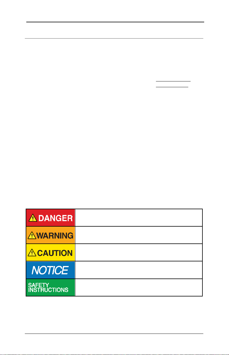
1.2 Safety........................................................................................................................3
2Product Description................................................................................................. 5
2.1 Technical Data ..........................................................................................................6
3Installation.............................................................................................................. 7
3.1 Mechanical ...............................................................................................................7
3.2 Hydraulic...................................................................................................................9
4Commissioning...................................................................................................... 10
4.1 Flushing ..................................................................................................................10
4.2 Inspection and Function Test..................................................................................10
5Maintenance and Service....................................................................................... 11
5.1 Preventative Maintenance .....................................................................................11
5.2 Recommended Spare Parts.....................................................................................11
6Parts Lists.............................................................................................................. 12
6.1 Top-Level Assembly ................................................................................................12
6.2 Control Cylinder Parts List ......................................................................................15
6.3 Valve Assembly Parts List........................................................................................16
7Warranty............................................................................................................... 17

7085-S Power Assist Cylinder Kobelt Manufacturing Co. Ltd
Rev A MNL-7085-S 3 of 18
1INTRODUCTION
1.1 CONTACT
Kobelt Manufacturing Co. Ltd.
8238 129th Street
Surrey, British Columbia
Canada, V3W 0A6
Sales Tel:
Fax:
Email:
Website:
+1-604-572-3935
+1-604-590-8313
sales@kobelt.com
www.kobelt.com
This document is intended to clearly present comprehensive product data and provide
technical information to assist the end user in design applications. Kobelt reserves the right,
without notice, to change the design, or construction, of any products and to discontinue or
limit distribution of any products. Kobelt also reserves the right to change, or update, without
notice, any technical information contained within this document.
Kobelt recommends that customers visit our website to check for updates to this manual.
Once a product has been selected for use, it should be tested by the user to ensure proper
function in all possible applications. For further instructions, please contact our distributors or
visit our website.
1.2 SAFETY
1.2.1 Safety Alerts
Throughout this manual, the following symbols, and their accompanying explanation, are
used to alert the user to special instructions concerning a service or operation that may be
hazardous if performed incorrectly or carelessly. The associated risk levels are stated below.
This symbol indicates an imminently hazardous situation which,
if not avoided, will result in death or serious injury.
This symbol indicates a potentially hazardous situation which, if
not avoided, could result in death or serious injury.
This symbol indicates a hazardous situation, which if not
avoided, could result in minor or moderate injury.
This symbol informs the reader of events not related to
personal injury but which there is a risk of damage to property
or equipment.
This symbol informs the reader of safety-related instructions or
procedures.

7085-S Power Assist Cylinder Kobelt Manufacturing Co. Ltd
Rev A MNL-7085-S 4 of 18
1.2.2 Notice to Installer
Disregarding the following safety measures can result in an accident-causing severe injury to
personnel and damage to material assets.
•Only use the product as directed in this manual.
•Never put the product into service if there is evidence of visible damage.
•Never put the product into service before fully completing installation and
commissioning.
•Do not carry out any modifications to the product.
•Only use authentic Kobelt spare parts.
•Observe all local regulations, directives and laws during the installation of this product.
•All installation, commissioning, and maintenance work must only be conducted by
qualified personnel. (For the purpose of this manual, qualified personnel are persons
who are familiar with the assembly, installation, commissioning, and operation of the
product and who have the qualifications necessary for their occupation.)
•Observe all specifications in this manual. If these guidelines are not followed and
damage occurs, the warranty will be voided.
1.2.3 Product Hazards
The moving components of the cylinder can generate forces
that can cause pinch or crush injuries. Keep body parts clear of
the unit when it is operating. Lock out any power sources
before working on the unit.
Exercise safety precautions pertaining to hydraulics including:
•Wearing safety glasses.
•Exhausting pressure and locking out the pressure
source.
•Being qualified to work on hydraulics.
•Never look for a leak by running your hand/fingers
along a pressurized hydraulic line.
To ensure the product does not get damaged during storage,
transportation and installation:
•Store the unit with the cylinder fully retracted.
•Ensure all plugs remain in place until the unit is ready
to be connected to hydraulics.

7085-S Power Assist Cylinder Kobelt Manufacturing Co. Ltd
Rev A MNL-7085-S 5 of 18
2PRODUCT DESCRIPTION
The 7085-S cylinders are power-assist cylinders that are controlled via inputs from fluid
pressurized by a helm pump but are powered by a machine-driven pump. This configuration
enables responsive steering while requiring minimal human effort. In the case of a failure of
the machine-driven pump the unit automatically switches to manual mode which allows for
steering via helm pump pressure only. 7085-S cylinders consist of three main subunits which
are the main cylinder, the control cylinder, and the valve and are identified in Figure 1 below.
Figure 1 - 7085-SB overview diagram
This product comes in balanced and unbalanced model. Both models cylinder comes in stroke
configurations of 10, 12, 16 and 20 inches. Technical specifications of the cylinder models can
be found in Table 1 on page 6. Expected torque values for 35° and 45° tillers can be found in
Table 2 and Table 3.
Before ordering any steering system, it is required that a
steering gear torque and rudder calculation be done to ensure
the system is appropriately sized and the correct mix of
pressure, displacement, stroke, parts, and torque is selected.
Contact you local Kobelt partner to review this information.

7085-S Power Assist Cylinder Kobelt Manufacturing Co. Ltd
Rev A MNL-7085-S 6 of 18
2.1 TECHNICAL DATA
Table 1 - Cylinder technical specifications
Model #
7085-SX10
7085-SX12
7085-SX16
7085-SX20
Stroke
± .02” [.05 cm]
10.00”
25.40 cm
12.00”
30.48 cm
16.00”
40.64 cm
20.00”
50.80 cm
Design pressure
1,000 psi
69 bar
Working pressure
800 psi
55 bar
Force at working
pressure - Bal.
6,283 lbf
27.9 kN
Force at working
pressure - Unbal. *
13,980 lbf
62.2 kN
Recommended fluid
ISO VG 32, VI 60 hydraulic oil
ISO 4406 cleanliness of 20/18/15
Displacement, main
cylinder - Bal.
78.5 in3
1,287 cc
94.2 in3
1,544 cc
125.7 in3
2,059 cc
157.1 in3
2,574 cc
Displacement, main
cylinder - Unbal. *
174.8 in3
2,864 cc
209.7 in3
3,436 cc
279.6 in3
4,582 cc
349.5 in3
5,727 cc
Displacement,
control cylinder
9.2 in3
151 cc
11.0 in3
181 cc
14.7 in3
241 cc
18.4 in3
302 cc
Ambient
temperature
14 to 122 °F
-10 to 50 °C
*Data expressed for paired configuration.
Operating outside of ambient temperature range and above
maximum pressure can result in damage to the unit and
reduced operational life and will void the warranty.
Table 2 –Balanced cylinder torque output*
Model #
7085-SB10
7085-SB12
7085-SB16
7085-SB20
Torque, 35° tiller
at max angle
3,739 lbf·ft
517 kg·m
4,487 lbf·ft
620 kg·m
5,982 lbf·ft
827 kg·m
7,478 lbf·ft
1,034 kg·m
Torque, 45° tiller
at max angle
-
-
4,189 lbf·ft
579 kg·m
5,236 lbf·ft
724 kg·m
*7085-SB10 & -SB12 cannot be used with 45° tillers.
Table 3 –Pair of unbalanced cylinder torque output*
Model #
7085-SU10
7085-SU12
7085-SU16
7085-SU20
Torque, 35° tiller
at max angle
8,319 lbf·ft
1150 kg·m
9,983 lbf·ft
1380 kg·m
13,310 lbf·ft
1840 kg·m
16,638 lbf·ft
2,300 kg·m
Torque, 45° tiller
at max angle
-
-
9,320 lbf·ft
1,289 kg·m
11,650 lbf·ft
1,611 kg·m
*7085-SU10 & -SU12 cannot be used with 45° tillers.

7085-S Power Assist Cylinder Kobelt Manufacturing Co. Ltd
Rev A MNL-7085-S 7 of 18
3INSTALLATION
Figure 2 - 7085-S rotation extents and hydraulic connections
3.1 MECHANICAL
The mounting of the cylinder should precede the connection of the unit to hydraulics if
possible. Figure 2 above indicates the rotation limits of the cylinder that should not be
exceeded. Also note that the rotation limits must be adhered to through the entire range of
motion of the cylinder, not just in the midships position. Dimensions of the cylinder when
installed to a tiller arm can be found on Figure 3 on page 8 and the tables that follow it.
If the cylinder has already been connected to a hydraulic power
source, ensure that pressure has been exhausted and the
pressure source has been locked out.
The cylinder foot must be mounted with fitted bolts or welded
stops must be installed to both ends of the foot. See Figure 3.
Ensure that the unit is mounted to a foundation that is capable
of support the loads that it can generate. If this is not taken into
consideration, then damage to the mounting structure can
occur.

7085-S Power Assist Cylinder Kobelt Manufacturing Co. Ltd
Rev A MNL-7085-S 8 of 18
Figure 3 - 7085-SXXX installed dimensions.
Table 4 - 7085-SXXX dimensions for 35° (ϑ) rudders
Model
Stroke (S)
R
X
E
F*
7085-SX10
10"
254 mm
8.72"
221.4 mm
7.14"
181.4 mm
36.19"
919.2 mm
5.06"
128.5 mm
7085-SX12
12"
304.8 mm
10.46"
265.7 mm
8.57"
217.6 mm
39.19"
995.4 mm
7.06"
179.3 mm
7085-SX16
16"
406.4 mm
13.95"
354.3 mm
11.43"
290.2 mm
45.19"
1147.8 mm
11.06"
280.9 mm
7085-SX20
20"
508 mm
17.43"
442.8 mm
14.28"
362.7 mm
51.19"
1300.2 mm
15.06"
382.5 mm
*F is not applicable for unbalanced model.
Table 5 - 7085-SBXX dimensions for 45° angle (ϑ) rudders**
Model
Stroke (S)
R
X
E
F*
7085-SX16
16"
406.4 mm
11.31"
287.4 mm
8.00"
203.2 mm
45.19"
1147.8 mm
11.06"
280.9 mm
7085-SX20
20"
508 mm
14.14"
359.2 mm
10.00"
254.0 mm
51.19"
1300.2 mm
15.06"
382.5 mm
*F is not applicable for unbalanced model.
**7085-SX10 and 7085-SX12 cannot be used with 45° rudders.

7085-S Power Assist Cylinder Kobelt Manufacturing Co. Ltd
Rev A MNL-7085-S 9 of 18
3.2 HYDRAULIC
Exercise safety precautions pertaining to hydraulics including:
•Wearing safety glasses.
•Exhausting pressure and locking out the pressure
source.
•Being qualified to work on hydraulics.
•Never look for a leak by running your hand/fingers
along a pressurized hydraulic line.
Before connecting the hydraulic lines to the cylinder ensure that all the hydraulic lines in the
steering system have been flushed and that the hydraulic oil is free of any contamination. The
cleanliness of the system must be at an ISO 4406 rating of 20/18/15 or better.
All connections are made to the valve. Hydraulic connections are specified in Figure 2 on page
7. The pressure line should have a minimum pressure rating of 2250 psi. For balanced model
If required, a secondary slave cylinder can be connected to the valve which allows for
additional rudder torque. For unbalanced model system should have a secondary slave
cylinder. Secure the piping against vibration with pipe clamps spaced every 3 feet (1 m).
ISO VG 32 is recommended for most steering system installations. If the environment is
exceptionally warm or cold, then viscosity grades 46 or 22 should be considered, respectively.
Do not use transmission or brake oil.
Failure to flush the system can result in premature failure of cylinder
components and seals.

7085-S Power Assist Cylinder Kobelt Manufacturing Co. Ltd
Rev A MNL-7085-S 10 of 18
4COMMISSIONING
4.1 FLUSHING
Before subjecting the steering system to full hydraulic pressure, the lines must be flushed to
an ISO 4406 cleanliness rating of 20/18/15.
4.2 INSPECTION AND FUNCTION TEST
Prior to putting the vessel into service perform a quick inspection and function test of the
unit:
1. Check that the mounting bolts are properly installed.
2. Check that all hydraulic connections are tight and are not leaking.
3. Check cylinder and tiller position against general arrangement drawing.
4. Check the tiller bolt installation.

7085-S Power Assist Cylinder Kobelt Manufacturing Co. Ltd
Rev A MNL-7085-S 11 of 18
5MAINTENANCE AND SERVICE
5.1 PREVENTATIVE MAINTENANCE
•Monthly (12 times per year)
oInspect connections for leaks.
•Quarterly (4 times per year)
oVerify adequate oil level.
5.2 RECOMMENDED SPARE PARTS
As a minimum Kobelt recommends the following spare parts are on-hand:
Table 6 - Recommended spares
Quantity
Part Number
Description
1
7085-SB-RK
Balanced model repair kit
1
7085-SU-RK
Unbalanced model Repair kit
For detailed parts lists see section 6 Parts Lists of this manual.
It is recommended that any required service work on a Kobelt
product be performed by a qualified individual. Please contact the
nearest Kobelt authorized distributor for assistance.

7085-S Power Assist Cylinder Kobelt Manufacturing Co. Ltd
Rev A MNL-7085-S 12 of 18
6PARTS LISTS
6.1 TOP-LEVEL ASSEMBLY
Figure 4 - 7085-SXXX top level assembly parts diagram

7085-S Power Assist Cylinder Kobelt Manufacturing Co. Ltd
Rev A MNL-7085-S 13 of 18
Table 7 - 7085-SXXX top level assembly parts list
Item
7085-SB10
7085-SU10
7085-SB12
7085-SU12
7085-SB16
7085-SU16
7085-SB20
7085-SU20
Part Number
Description
1
1
1
1
1
1
1
1
1
7085-0001
Foot
2
2
2
2
2
2
2
2
2
7085-0029
Shoulder bolt-long
3
1
1
1
1
1
1
1
1
7085-0003
End cap, swivel end
4
1
1
-
-
-
-
-
-
7085-S10
Control cylinder
4
-
-
1
1
-
-
-
-
7085-S12
Control cylinder
4
-
-
-
-
1
1
-
-
7085-S16
Control cylinder
4
-
-
-
-
-
-
1
1
7085-S20
Control cylinder
5
1
1
-
-
-
-
-
-
7085-1018
Cylinder tube
5
-
-
1
1
-
-
-
-
7085-1218
Cylinder tube
5
-
-
-
-
1
1
-
-
7085-1618
Cylinder tube
5
-
-
-
-
-
-
1
1
7085-2018
Cylinder tube
6
2
2
2
2
2
2
2
2
7039-0623
Hydraulic fitting
7
2
2
2
2
2
2
2
2
7039-0423
Hydraulic fitting
8
2
2
2
2
2
2
2
2
7039-0322
Hydraulic fitting
9
2
2
2
2
2
2
2
2
7085-0013
Bracket
10
2
2
-
-
-
-
-
-
7085-1032
Main tie rod-long
10
-
-
2
2
-
-
-
-
7085-1232
Main tie rod-long
10
-
-
-
-
2
2
-
-
7085-1632
Main tie rod-long
10
-
-
-
-
-
-
2
2
7085-2032
Main tie rod-long
11
4
4
-
-
-
-
-
-
7085-1033
Main tie rod-short
11
-
-
4
4
-
-
-
-
7085-1233
Main tie rod-short
11
-
-
-
-
4
4
-
-
7085-1633
Main tie rod-short
11
-
-
-
-
-
-
4
4
7085-2033
Main tie rod-short
12
2
1
2
1
2
1
2
1
7085-0015
Main shaft guide
13
2
1
2
1
2
1
2
1
7085-0016
Seal retainer
14
1
1
1
1
1
1
1
1
7085-0004
Rod end assembly
15
2
2
2
2
2
2
2
2
1022-0273
Nut, hex jam
16
1
-
-
-
-
-
-
-
7085-B10-SUB
Piston-rod assembly
16
-
1
-
-
-
-
-
-
7085-U10-SUB
Piston-rod assembly
16
-
-
1
-
-
-
-
-
7085-B12-SUB
Piston-rod assembly
16
-
-
-
1
-
-
-
-
7085-U12-SUB
Piston-rod assembly
16
-
-
-
-
1
-
-
-
7085-B16-SUB
Piston-rod assembly
16
-
-
-
-
-
1
-
-
7085-U16-SUB
Piston-rod assembly
16
-
-
-
-
-
-
1
-
7085-B20-SUB
Piston-rod assembly
16
-
-
-
-
-
-
-
1
7085-U20-SUB
Piston-rod assembly
Continued next page…

7085-S Power Assist Cylinder Kobelt Manufacturing Co. Ltd
Rev A MNL-7085-S 14 of 18
Continued from previous page…
Item
7085-SB10
7085-SU10
7085-SB12
7085-SU12
7085-SB16
7085-SU16
7085-SB20
7085-SU20
Part Number
Description
17
12
12
12
12
12
12
12
12
1022-0164
Nut, hex
18
12
12
12
12
12
12
12
12
1023-0314
Lock washer
19
1
1
1
1
1
1
1
1
7085-0006
End cap
20
1
-
1
-
1
-
1
-
7085-SB-RK
Repair kit
20
-
1
-
1
-
1
-
1
7085-SU-RK
Repair kit
21
2
2
2
2
2
2
2
2
7085-0009
Mounting bracket
22
2
2
2
2
2
2
2
2
1023-0311
Lock washer
23
2
2
2
2
2
2
2
2
1001-1112
Screw, hex head
24
4
4
4
4
4
4
4
4
1001-1012
Screw, hex head
25
1
1
1
1
1
1
1
1
7085-0008
Spring cover
26
2
2
2
2
2
2
2
2
7039-0321
Hydraulic fitting
27
1
1
1
1
-
-
-
-
1340-58-20-58
Hose assembly
27
-
-
-
-
1
1
1
1
1340-58-24-58
Hose assembly
28
1
1
1
1
1
1
1
1
7085-SA
Valve assembly
29
2
2
2
2
2
2
2
2
7039-0625
Hydraulic fitting
30
2
2
2
2
2
2
2
2
7039-0426
Hydraulic fitting
31
4
4
4
4
4
4
4
4
7039-0181
Hydraulic fitting
32
1
1
1
1
-
-
-
-
1340-38-16-38
Hose assembly
32
-
-
-
-
1
1
-
-
1340-38-21-38
Hose assembly
32
-
-
-
-
-
-
1
1
1340-38-24-38
Hose assembly
33
1
1
1
1
1
1
1
1
1340-58-20-58
Hose assembly
34
1
1
1
1
1
1
1
1
1340-38-16-38
Hose assembly
35
1
1
-
-
-
-
-
-
7085-1017
Valve spacer
35
-
-
1
1
-
-
-
-
7085-1217
Valve spacer
35
-
-
-
-
1
1
-
-
7085-1617
Valve spacer
35
-
-
-
-
-
-
1
1
7085-2017
Valve spacer
36
1
1
-
-
-
-
-
-
7085-1036
Tie rod, valve spacer
36
-
-
1
1
-
-
-
-
7085-1236
Tie rod, valve spacer
36
-
-
-
-
1
1
-
-
7085-1636
Tie rod, valve spacer
36
-
-
-
-
-
-
1
1
7085-2036
Tie rod, valve spacer
37
2
2
2
2
2
2
2
2
1023-0310
Lock washer
38
2
2
2
2
2
2
2
2
1022-0110
Nut, hex
39
-
1
-
1
-
1
-
1
7085-0038
Rear end cap
40
2
2
2
2
2
2
2
2
7085-0028
Shoulder bolt-short
41
1
1
1
1
1
1
1
1
7085-0002
Swivel

7085-S Power Assist Cylinder Kobelt Manufacturing Co. Ltd
Rev A MNL-7085-S 15 of 18
6.2 CONTROL CYLINDER PARTS LIST
Figure 5 - 7085-SXX control cylinder parts diagram
Table 8 - 7085-SXX control cylinder parts list
Item
Quantities
Part Number
Description
7085-S10
7085-S12
7085-S16
7085-S20
1
1
-
-
-
7085-S10-SUB
Piston-rod assembly-10”
1
-
1
-
-
7085-S12-SUB
Piston-rod assembly-12”
1
-
-
1
-
7085-S16-SUB
Piston-rod assembly-16”
1
-
-
-
1
7085-S20-SUB
Piston-rod assembly-20”
2
4
4
4
4
7085-0027
Hex nut
3
2
2
2
2
7085-0012
End cap
4
1
1
1
1
7085-SB(U)-RK
Repair kit
5
1
-
-
-
7085-1019
Cylinder tube-10”
5
-
1
-
-
7085-1219
Cylinder tube-12”
5
-
-
1
-
7085-1619
Cylinder tube-16”
5
-
-
-
1
7085-2019
Cylinder tube-20”
6
1
-
-
-
7085-1034
Tie rod, 10”
6
-
1
-
-
7085-1234
Tie rod, 12”
6
-
-
1
-
7085-1634
Tie rod, 16”
6
-
-
-
1
7085-2034
Tie rod, 20”
7
1
-
-
-
7085-1035
Tie rod, 10”
7
-
1
-
-
7085-1235
Tie rod, 12”
7
-
-
1
-
7085-1635
Tie rod, 16”
7
-
-
-
1
7085-2035
Tie rod, 20”
8
1
1
1
1
1022-0161
Hex nut
9
1
1
1
1
7085-0007
Servo link
10
2
2
2
2
7085-0014
Seal cover
11
4
4
4
4
1012-0808
Screw, pan head Philips
12
2
2
2
2
1022-0164
Hex nut
13
2
2
2
2
1023-0114
Flat washer
14
1
1
1
1
7085-0005
Linkage

7085-S Power Assist Cylinder Kobelt Manufacturing Co. Ltd
Rev A MNL-7085-S 16 of 18
6.3 VALVE ASSEMBLY PARTS LIST
Figure 6 - 7085-SA valve parts diagram
Table 9- 7085-SA valve parts list
Item
Quantity
Part Number
Description
1
1
1001-1112
Screw, hex head
2
2
7085-0037
Washer
3
2
1201-0216
Spring
4
2
7085-0046
Bore protector
5
1
7185-0011
Spool housing block
6
1
7185-0010
Outlet port block
7
2
7085-0025
Outer spool
8
1
7085-0024
Inner spool
9
6
1002-0820
Screw, socket head
10
1
7085-0039
Sleeve
11
1
7085-SA-RK
Repair kit
12
2
7085-0026
Bushing
13
1
1023-0237
Flat washer
14
1
1022-0261
Nut, hex jam
15
2
1022-0161
Nut, hex

7085-S Power Assist Cylinder Kobelt Manufacturing Co. Ltd
Rev A MNL-7085-S 17 of 18
7WARRANTY
Kobelt Manufacturing Co. Ltd. (“Kobelt”) warrants the Products and Parts manufactured by
Kobelt to be free from defects in workmanship or material and that said products are
designed mechanically and functionally to perform to specifications.
This warranty is effective providing:
•The equipment is used within the intended operating conditions and in accordance with
Kobelt recommendations.
•The equipment is installed according to equipment diagrams, specifications, and
recommendations which Kobelt has provided.
This warranty becomes invalid if the factory supplied serial number has been removed or
altered on the product. This warranty does not cover cosmetic damage or damage caused by
an act of God, accident, misuse, abuse, negligence or modification of any part of the product.
This warranty does not cover damage due to improper operation or maintenance, connection
to inappropriate equipment or attempted repair by anyone other than an authorized Kobelt
representative.
Upon identification of a potential issue or defect with a Kobelt Product or Part, the Warranty
Applicant (“Applicant”) must immediately contact Kobelt and describe the issue in writing, by
letter, fax, email or other electronic conveyance. Kobelt will then assess the cause of the
defect and determine warranty applicability and appropriate remediation.
If any part is found to be defective, Kobelt will replace said part FOB the Kobelt factory
provided that any such defective part is returned by the Buyer with freight and applicable
forwarding charges prepaid by the Buyer. Kobelt’s sole obligation to the Applicant will be to
repair or replace the defective part with same or similar product, to a maximum value of the
list price of the product or part. The Kobelt warranty does not cover labour charges, travel or
any other associated expenses.
All Products and Parts manufactured by Kobelt, with the exception of brake discs and pads,
are subject to a warranty against manufacturer’s defects in materials or workmanship for a
period of two (2) years from the date of purchase. Thrusters and brake discs are subject to a
one (1) year warranty period, and brake pads and linings are not covered by warranty.
Kobelt will be responsible for all Products or Parts sold by Kobelt but manufactured by 3rd
party manufacturing companies. However, these products and parts are subject to applicable
3rd party warranties and may not be the same as the Kobelt warranty.

7085-S Power Assist Cylinder Kobelt Manufacturing Co. Ltd
Rev A MNL-7085-S 18 of 18
Page Intentionally Left Blank

Kobelt Manufacturing Co. Ltd.
8238 129th Street
Surrey, British Columbia,
Canada, V3W 0A6
Sales Tel: +1-604-572-3935
Fax: +1-604-590-8313
Email: sales@kobelt.com
Website: www.kobelt.com
Made in Canada / Printed in Canada
Keivan
Ashouei
Digitally signed by
Keivan Ashouei
Date: 2023.03.21
11:44:08 -07'00'
This manual suits for next models
12
Table of contents
Other Kobelt Industrial Equipment manuals

Kobelt
Kobelt 6555 User manual

Kobelt
Kobelt 5022-SA Instruction Manual

Kobelt
Kobelt 5021-A Instruction Manual

Kobelt
Kobelt 7174 Service manual

Kobelt
Kobelt 5040-SA Instruction Manual

Kobelt
Kobelt 7174 Instruction Manual

Kobelt
Kobelt 5023-SA Instruction Manual

Kobelt
Kobelt 5024-A Instruction Manual

Kobelt
Kobelt 7166 Electric Helm Instruction Manual

Kobelt
Kobelt 7065-SB Series User manual