KOCOM KCV-T701SM User manual

KCV-T701SM MANUAL
www.kocom.com
GUI Full Touch Videophone
AHD CCTV Compatible
●
7" Digital LCD Screen (NTSC/PAL)
●
Simple and Convenient UI & Full Capacitvive screen
●
Compatible with 1080p (FHD) AHD CCTV
(TVI, AHD, CVI)
●
Auto still image capture (Max 32 cuts) Door Camera
●
Connection up to 2 Door Cameras and
4 Monitors with Sub-interphone (KIP-32G)
●
Overall or individual calling available
●
Multifamily, Apartment application
(KLP-C420 SYSTEM)
[7" Digital Color LCD Videophone]

2
Cautions for set-up
Warnings for Usage
Cautions for Repairs and Maintenance
·Do not install this unit near the water and dust, for example, in a bathroom or near the washing machine. It caused fire and electric shock.
·Do not install this unit near the fire, for example, near kitchen sink, heater or the like.
·Do not install near the noxious gar such as Hydrogen Sulfide, metal power and the like.
·Do not install near the water and chemicals.
·Do not give any damage, break and modify the plug. Overloading, heating, pulling causes the damage.
·Do not place the plug near the heater. The damaged code causes fire and electric shock. Do not pull the power code when unplugging.
·The damaged code causes fire and electric shock. Must pull with plug. Do not touch with wet hands. It causes the electric shock.
·Do not use any other voltage, except the marked regular voltage.
·Do not use the power terminal at the units to other electric device except the designed device.
·Do not install the units at the leaking place if it doesn’t have any waterproof mark. Do not install the unit when the power is on.
·Install the circuit breaker after checking the safety such as electric shock and leakage. Turn off the power before you install or A/S
·Check the suitability of the wire for installing when you use the exiting wire.
·Do the wiring work by using the designed material.
·Connect the electric wire with the designed ways and ground.
·Do not connect with any other devices except the designed devices to compose the system.
·Unplug electric wire and communication wire from the units before relocate the product.
For safe use, please stick to the following cautions.
Cautions for safety
·Do not use liquid or aerosol cleaners. Use a damp cloth for cleaning.
·Set the device of the wall-mounted type not to fall. Falling from an earthquake causes personal injury.
·The law limits distributing the power wire to an authorized person from government.
The work from an unaurhtorized person cause fire or electric shock.
·Place this unit securely on a stable surface. Serious damafe and/or injury may result if the unit falls.
·Do not set up this unit near the leaking place because it may expose you to dangerous voltages or other risks.
·Even if your product is water proof, do not install it slanted place of water leakage, which can a short circuit.
·Fix the product on the wall safely according to the installation guideline to prevent any damage or injury.
·
The disconnect device shall remain readily operable.
·The work of distributing wires needs skills and experiences. So please, for assistance, contact your dealer or call service center.
·The communication wire should be built in being distant from the power source.
This may result in the risk of fire, electric shock and communication disorder.
·Setting the communication wire in a high humid place such as outside without any protection from rain causes the communication disorder.
·Keep the hook at the wall-mounted device safe. The hook may cause the physical injury.
·Think about the thickness and quality of wall material. The unqualified material may make the device fall.
·Keep the inside of the device clean. Having the dust inside without any cleaning for a long time causes the fire.
If necessary, contact your dealer or service center to get cleaning service.
Caution
Warning
·Unplug this device when you want to check the inside. If there is no plug, please, turn off the circuit breaker.
·Unplug this device when you try to move it to another place.
If the electric line is connected inside of the unit, please contact your dealer or service center.
·Please do not dispose this manual after reading the instructions carefully. ·Please read all instructions to set up rightly.
·This Cautions for Safety may include items that are not contained in specifications of the product that consumer purchases.
To help our customers to understand this manual, to prevent any personal injury or property damage, some marks are used in the manual.
The marks and the drawing signs are below. Please, understand the marks before reading the manual.
Sign to show what not to do.
Sign to tell you that you should follow the instructions.
Sign to tell you that you can't disassemble this unit.
Mishandling the device with ignoring this sign may result in serious injury or death.
Mishandling the device with ignoring this sign may result physical injury or material damage.
The important marks in the manual.
The meaning of the drawing signs.
Sign to tell you that you must unplug the unit.

3
Cautions for Use
Things You Need to Know
Videophone
Cautions
Cautions for Abnormality
Safety Instructions, Warnings and Cautions of Each System
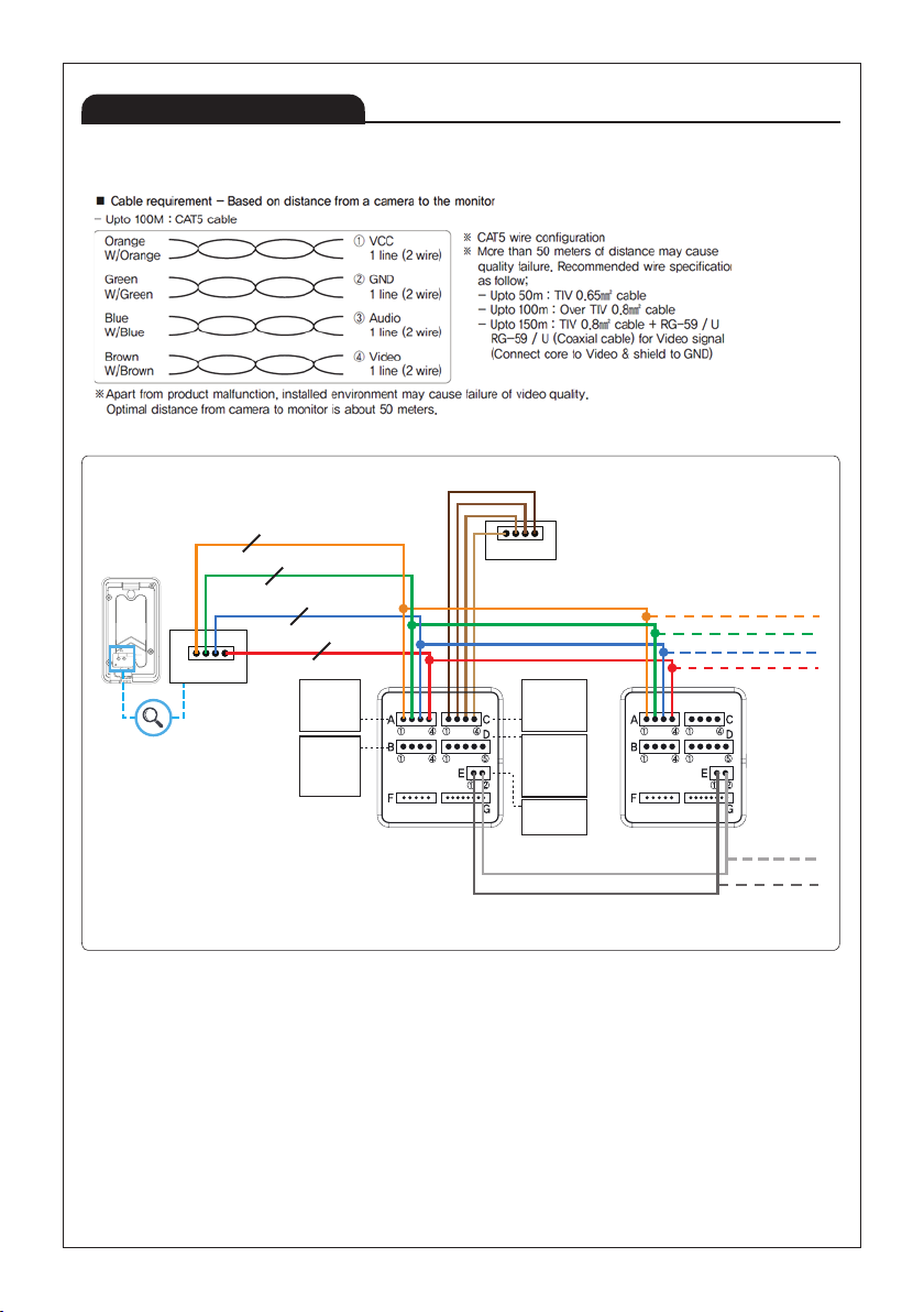
·This product is designed as a home videophone and cannot use continuously like monitor camera.
·If there is temperature difference between inner part of camera and surrounding, dew condensation occurs on camera lens and may disturb image.
If dew condensation is removed from camera lens, image quality recovers.
·White LED light examination range is narrower than camera shot range at night, so there is less amount of light at night than day.
So it is difficult to see the face in low illumination condition due to noise increase on screen, but it is not from defect.
·Monitor screen (liquid crystal panel) is not in defect when some pixels always light or black out.
·Please install monitor and camera over 5cm away.
Also, avoid installing at a place with too much noise, because too much noise around camera causes phone call inferiority.
·Do not place an object within 20cm in front of monitor. It causes phone call inferiority, especially because microphone is installed at the top of monitor.
·If strong light such as sunlight flows into camera module, screen saturation (or strange mark) and image shaking might occur.
·This is not a defect, so please do not install camera where a direct ray of light do not flow if possible.
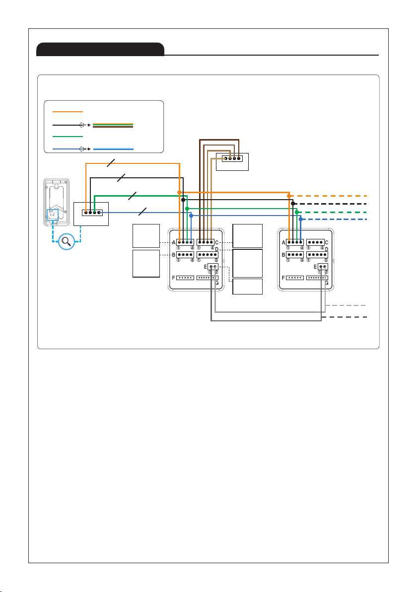
·Separate the AC/DC wire with the hook of the wall-mounted type when installing. 쪾 ·Connect the wire after peeling the wires properly.
·Do not distribute signal line with AC line. ·Use the designed driver to connect the wire to terminal.
·Do not clean the LCD with the damp cloth for cleaning. Use the only dry and soft cloth. ·Do not install the main gate monitor at the leaking place.
·In some cases there is occurrence of product destruction, malfunction, noise mixing and picture quality deterioration due to mixing of other tool's
induced. voltage or thunder with communication wiring of monitor/camera, monitor/extended monitor.
Do not wire with power line such as outdoor wiring or AC power, or phones and other tools.
·You cannot use it if you incorrectly wire the AC voltage between monitor/camera, monitor/extended monitor.
Call the store or agency where you purchased this product and consult to solve the problem.
Beware that unfixable damage might be caused due to authorizing AC voltage on communication wiring of monitor/camera, monitor/extended monitor.
·Do not ever disjoint this product. It may cause electrocution accident when touching high-voltage circuit inside this product.
·Outside power authorizing this product must be confirmed of product description and use rated voltage.
Beware that if higher voltage is authorized, unfixable damage might be caused due to product destruction.
·Power must be connected to domestic voltage (product rated voltage) consent or interior wiring.
If connected to other motive power or inverter-type power, product destruction, noise mixing, and picture distortion may occur.
·Do not drop this product. Glass is used for monitor and might break, or cause other circuit inferiority.
In such case, immediately turn down the power switch, and call to consult agency or store in which this product was purchased.
·Keep away from any conditions where water splatters or falls. Do not place anything containing water like a vase on the product.
·If you install a product nearby an antenna used for broadcast media, image could be distorted or mixed with a voice so that it is likely not to work
properly in some functions.
·Avoid installing near tools with strong electromagnetic waves such as microwaves and cell phones, as it may cause a picture distorted or a voice with
a noise. In that case, the product is likely not to work properly in some functions.
·Do not install monitor in following places.
① Above or around water heater, rice-cooker, heater ② Place exposed to direct rays of the sun
③ Place with temperature below 0'C such as cold store ④ Place with high humidity such as bathroom, washroom, heated room
⑤ Place with a lot of gas, dust, smoke ⑥ Dangerous place with sprays of water or chemicals
·Do not wipe with insecticide, drugs or chemicals such as thinner and alcohol, or it may damage
the surface of this product.
·Beware of occurrence of image quality deterioration or malfunction from cause of humidity due to
penetration of chemicals or water into camera’s urea resins.
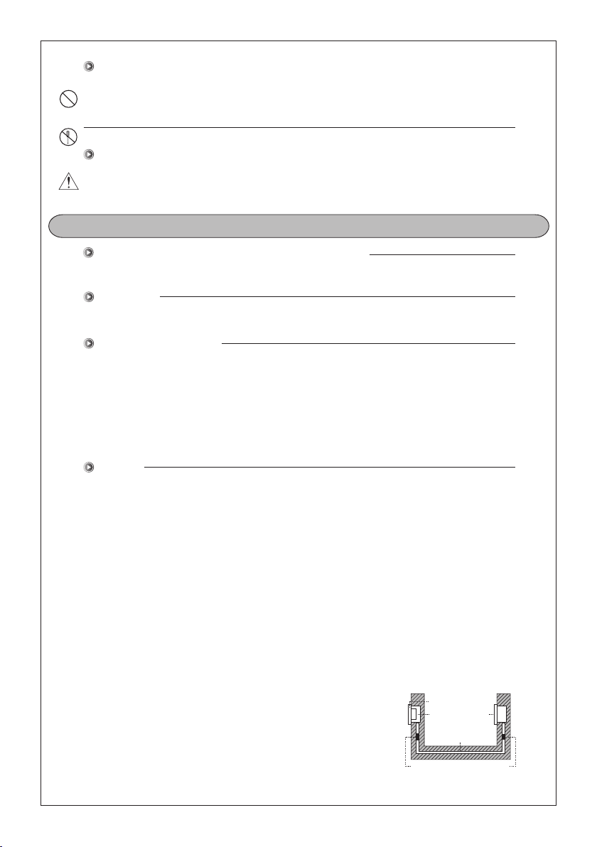
·As in the picture, it prevents temperature difference of camera (outside) and monitor (inside), and
removes dew condensation caused by humidity of camera window.
·Camera must be installed when wall cement is completely dry.
·When product is installed in winter below -5'C, wait for approximately 2 hours to connect. Dew formation
in monitor and camera due to temperature difference inside and outside may cause product defect.
·Avoid installing monitor and camera in place directly exposed to heat or where gas noxiousness is highly occurring.
·Do not disassemble this unit at will as this device is composed by precision parts. 쪾 ·Install the unit by following the set-up instructions of Kocom.
·Do not touch or insert any foreign substances, for example, sticker, magnetic, opener and the like.
·Make U-type at the end of wires as the rain can effect on the system by following the wires during the rainy season.
·This unit is not designed for security purpose. 쪾·Do not handle the unit with the wet hands.
·Do not place a pot with water or a small metal material on the Units.
·Do not cover the ventilating opening or put any metal material in the units. 쪾
·During thunderstorms, avoid using this unit. There may be a remote risk of an electric shock from lighting.
·Any changes or modifications to the equipment not expressly approved by the party responsible for compliance could void user`s authority to operate the equipment.
·Change the damaged electric code.
·Unplug this unit from plug socket and refer servicing to an authorized service center when the following conditions occur:
·If liquid has been spilled into the unit. 쪾·If the unit does not work normally by following the operating instructions.
·If the unit exhibits a distinct change in performance. ·If the unit has been dropped or physically damaged.
·Do not disassemble the back and cabinet cover.
Tapón de la tubería de PCV con
sustancias adiabáticas para
prevenir la circulación del aire
Caja con
tubería
Monitor
Tubería
Cámara
(Exterior, Puerta)
Caution

4
■Door camera installation
KC-MC24(D1)
·
KC-MC24M
Wall Screw
(4X16mm) Camera
front
Screw
(4X10mm)
After fix the rear bracket with 4 screw, put the Door Camera into the grooves of rear bracket,
and then fix it with hexagon screws and stick the finishing materials.
※
Installation Location
■ Monitor installation
■Directly connecting cut-off power cord with power wire
1) Personal electrical work must be avoided. Please find local installer or electrician for installation.
2) power cords must be insulated with insulation tape after the work.
[Exposed wires may cause fire or electric shock.]
3) Highly recommend to cut main power supply off before electrical work.
1) Remove metal wall hanger bracket behind monitor.
2) Install metal wall hanger bracket on 1 type box or wall with attached screw.
3) Connect wiring to monitor back terminal referring to product connection diagram.
4)
Hang monitor on metal wall hanger bracket
5) Test the product status if the monitor is both plugged in and switched on.
■ Caution of camera installation
·Avoid installing camera exposed to direct sunlight or lights.
·Back light or shadow on visitor's face may occur difficult recognition.
·Avoid installing camera in places such as the following picture.
(1) Place illuminating sky as background
(2) Place with white wall reflecting direct ray of light
(3) Place with direct ray of light
■ Camera installation location
·Recommended installation
height of door camera is
where lens is about 1,400mm
above the floor. In this case,
camera stack center (Buried
box) is above 1,390mm
above ground level.
■ Monitor installation location
·Recommended installation
height is about 1,500mm
where screen center is at
eye level. In this case,
wall - hanging metal center
(center of piping) is 1,450mm
above ground level.
KC-S81M(D1)
·
KC-S81M2
Wall
Screw
Flush
mount
bracket
Main
body Sun
visor
Wall
Wall
KC-MC20(D1)
·
KC-MC20M
Flush
mount
bracket
Main
body
Main
body
Sun
visor
Sun visor screw
2X4(3EA)
Angle
supporter
Screw cover
(2EA) Screw cover
(2EA)
Main body screw
4X18(2EA)
Surface mount type
Surface mount type Flush mount type
Main body screw
4X18(2EA)
Bracket screw
4X25(2EA)
Bracket screw
4X25(2EA)
※When using angle supporter,
if main body screw(4X18) does not fit, please use spare screw(4X20)
KC-MC30M(2M,AHD)
Wall
4X25mm
Screw
4X8mm
Screw
Rear Bracket
Camera front
Wrench
Name plate
KC-Q81P(D1)
Screw
Rear bracket
Camera front

5
Components of Product
Specifications
■Wall hanger
■Screws
4X25mm 4ea
■Monitor
※
Door Camera Wiring : Polarzied 4 wire(VCC[12V] / GND / AUDIO / VIDEO)
※
Recommend adaptor : CT-140200 (14V) / UT60-140210-6-02(14V)
※
Kocom is not responsible of non verified power supply.
■Wire
4Pin cable camera x 2ea
5Pin cable door x 1ea
4Pin cable interphone x 1ea
2Pin cable data x 1ea for
ex_monitor
Adapter(CT-140200 or
UT60-140210-6-02)
※In case of Surface mount type, 'Sun Visor' and 'Angle Supporter' are packed together with
the 'product.'. Flush mount type includes 'flush mount bracket.'
[KC-MC24(D1)
·
KC-MC24M]
Finishing rubber
Screws for fixing camera
main body supporter
Screw for fixing camera
Bracket
4X10mm
4X16mm
[KC-MC20(D1)
·
KC-MC20M]
Screws Cover (2EA)
Sun visor screw
(2X4mm 3EA)
Bracket screw
(4X25mm 2EA)
Main Bbody screw
(4X18mm 2EA)
Sun Visor Flush Mount
Bracket
or
Angle
Supporter
Bracket [Option]
■Door Camera
[KC-S81M(D1)
·
KC-S81M2]
Lench 2.5mm 1EA
M3X8mm 1EA
4X50mm 2ea
■Door Camera
[KC-Q81P(D1)]
Bracket Sun visor
[Option]
Finishing rubber
Screws for fixing camera
main body supporter
4X10mm
[KC-MC30M(2M,AHD)]
Wall to bracket screws
Camera to bracket screw
"L" wrench
screw cover (KC-MB30)
Bracket
4X25mm
4X8mm
Monitor
Model No. KCV-T701SM AC TYPE KCV-T701SM DC TYPE
Power Source 100-240V~, 50/60Hz DC 14V-2A
Power Consumption 1.7W(±20%)(On Stand by), MAX 14W(±20%)(Full load)
Operating Temperature 0℃ ~ +40℃
LCD 7 inch LCD
Communication Type HandsFree Type
Input / Output Door camera : 2mm pitch 4Wire x 2
Door Open : 2mm pitch 5Wire x 1
Interphone : 2mm pitch 4Wire x 1
Inner DATA : 2mm pitch 2Wire x 1
Maximum wiring
distance
( UTP CAT5e or Coaxial )
Door camra to last VDP
1) D1(0.41M) Door camera : 100m UTP Cat5e
2) 2M Door camera : 50m UTP Cat5e
CCTV to VDP ---- 100m ( When using Coaxial cable (RG59))
Interphone to VDP ---- 10m
※ Refer to "product wiring" below for cable wiring
※ UTP CAT5e : The resistance of 100 m of cable should be 10 ohms or less.
Mount Type Surface mount
CCTV Type Analog HD Type ( TVI, CVI, AHD) , (720p , 1080p)
Still image Capture Max 32 cuts ( Still cut images are stored in internal memory. )
Dimension 218(W) X 119(H) X 22(D) mm 218(W) X 119(H) X 18(D) mm
Door
Camera
Model No. KC-Q81P(D1) KC-MC30M
KC-MC24(D1) KC-MC24M
KC-S81M(D1)
KC-S81M2 KC-MC20(D1) KC-MC20M
Resolution 0.41M 2M 0.41M 2M 0.41M 2M 0.41M 2M
Power Source DC 12±1V(Power from Monitor)
Power Consumption Max. 3W
Operating temperature -10℃ ~ +50℃
Dimension(mm)
75(W) x 136.5(H) x 18.5(D)
110(W) x 158(H) x 39(D) 96(W) x 127(H) x 32(D)
70(W) x 125(H) x 21(D)
40(W) x 120(H) x 22(D)
Viewing angle Diagonal 90˚
Adjusting Angle No Yes No

6
①
②
③
④
⑤
Name and Functions of Each Part
■ Monitor part
·Up side·Front
2
3
·Back
① 7" Touch LCD Montior with touch screen
② Microphone
③ DC Power ON/OFF Switch
④ Speaker
⑤ Terminal : Ports for Door camera1,2, Interphone, Door open, Inner data
■ Camera part
FG(FRAME GROUND)
⑤⑥ ④ ③ ② ①
A B
1 1 34
⑤⑥ ④ ③ ② ①
A B
1 1 34
KC-MC24(D1)
KC-MC24M
KC-S81M(D1)
KC-S81M2
① VCC
② GND
③ Audio
④ Video
⑤,⑥,⑥'Door(Non-polarity)
(⑤: COM, ⑥: NO, ⑥': NC)
⑦ Camera angle knob
(Only KC-MC30M)
⑧ Wire clamp
③
②
④
⑤
①
KC-MC24(D1)
KC-MC24M
KC-Q81P(D1) KC-Q81P(D1)
①②③④ ⑤⑥⑥'
KC-MC30M(2M,AHD) KC-MC30M(2M,AHD)
KC-MC20(D1)
KC-MC20M
KC-MC20(D1)
KC-MC20M
KC-S81M(D1)
KC-S81M2
① C-Mic : To communicate with Monitor
② Camera Lens
③ LED
④ Speaker
⑤ Call Button : Calls resident
·Front ·Back
15
4
①VCC(BLUE)
②GND(YELLOW)
③AUDIO(RED)
④VIDEO(WHITE)
A
B①COM(BLACK)
②NO(BROWN)
③NC(ORANGE)
①
②
③
④
⑤
⑥

7
■Camera mode diagram
Product Wiring Diagram
Maximum wiring distance : 100m(D1(0.41M) Camera, IN-OUT wiring must be done.)
50m(2M Camera, IN-OUT wiring must be done.)
(UTP CAT5e) *Refer to "Product wiring" below for cable wiring
The monitor that is installed furthest from
the camera should be set to Last device.
and the rest other monitors except the one
chosen as "Last Device" must be set as "X".
KC-S81M(D1)
KC-S81M(D1)
KIP-32G KIP-32G KIP-32G KIP-32G
Non-Polarized
Door Opener
DEVICE 1 DEVICE 2 DEVICE 3 DEVICE 4
Non-Polarized
ADAPTOR
28
8
2
2
2
4 4 4 4
KC-S81M(D1)
KIP-32G KIP-32G KIP-32G KIP-32G
Door Opener
ADAPTOR
Non-Polarized
DEVICE 1 DEVICE 2 DEVICE 3 DEVICE 4
CCTV
CCTV
CCTV
CCTV
8
2
2
2
4 4 4 4

8
■2M Door camera
Product Wiring Diagram
ALL 8 WIRES OF UTP CABLE SHALL BE USED TO CONNECT.
WIRES OF UTP CABLE SHALL BE DIVIDED AND USED AS PER THE DIAGRAM ABOVE.
UNCONNECTED WIRES OF UTP CABLE MAY CAUSE THE POOR QUALITY OF VIDEO IMAGE.
※
※
※
KIP-32G
BACK VIEW
④ ①
A. CAMERA 1
① CA1 VCC
② CA1 GND
③ CA1 AUDIO
④ CA1 VIDEO
B. CAMERA2 &
420 SYSTEM
① CA2 VCC
② CA2 GND
③ CA2 AUDIO
④ CA2 VIDEO
C. INTERPHONE
① INTER VCC
② INTER GND
③ INTER AUDIO
④ INTER SIGNAL
D. DOOR
① 12V
② GND
③ DOOR NO
④ DOOR COM
⑤ DOOR NC
E. INNER DATA
① DATA
② GND
VCC(DC12V) - Orange
GND - W/Orange, W/Green, W/Brown, Brown
VOICE - Green
VIDEO - Blue, W/Blue
A
1 4
KC-S81M(D1)
BACK VIEW
① ④
A
DEVICE 1
BACK VIEW DEVICE 2
BACK VIEW
1
4
1
2

9
■D1(0.41M) Door Camera
Product Wiring Diagram
KIP-32G
BACK VIEW
④ ①
A. CAMERA 1
① CA1 VCC
② CA1 GND
③ CA1 AUDIO
④ CA1 VIDEO
B. CAMERA2 &
420 SYSTEM
① CA2 VCC
② CA2 GND
③ CA2 AUDIO
④ CA2 VIDEO
C. INTERPHONE
① INTER VCC
② INTER GND
③ INTER AUDIO
④ INTER SIGNAL
D. DOOR
① 12V
② GND
③ DOOR NO
④ DOOR COM
⑤ DOOR NC
E. INNER DATA
① DATA
② GND
A
1 4
KC-S81M(D1)
BACK VIEW
① ④
A
DEVICE 1
BACK VIEW DEVICE 2
BACK VIEW
2
2
2
2
※ AS ABOVE DIAGRAM ILLUSTRATES, OPTIMAL DISTANCE FROM THE DOOR CAMERA TO THE FURTHEST MONITOR MUST
BE BELOW 20 METERS WHEN CONNECTING 2M CAMERA.

10
KIP-32G KIP-32G KIP-32G KIP-32G
KAM-D340
KLP-420
KC-S81M(D1)
KVS-A4P/A8P UTP CAT5e 4Px1
UTP CAT5e 4Px1
DEVICE 1 DEVICE 2 DEVICE 3 DEVICE 4
28
8
4 4 4 4
2
HOUSE1HOUSE2
CN1LOB_INLOB_OUTEX_POWER
4 14 1
5 14 14 11 2
■System mode diagram
※ KLP-420 SYSTEM must be connected to CAM2 port of the monitor
Polarized
4wire
Maximum wiring distance : 100m (The IN-OUT wiring must be done)
(UTP CAT5e) *Refer to "Product wiring" below for cable wiring
KC-S81M(D1)
KC-S81M(D1)
KIP-32G KIP-32G KIP-32G KIP-32G
UTP CAT5e 4Px1
UTP CAT5e 4Px1
Non-Polarized
Door Opener
UTP CAT5e 4Px1
DEVICE 1 DEVICE 2 DEVICE 3 DEVICE 4
Non-Polarized
UTP CAT5e 4Px1
UTP CATe 4Px1
ADAPTOR
KC-S81M(D1)
KIP-32G KIP-32G KIP-32G KIP-32G
Door Opener
ADAPTOR
Non-Polarized
DEVICE 1 DEVICE 2 DEVICE 3 DEVICE 4
CCTV
CCTV
CCTV
CCTV
8
2
2
2
4 4 4 4
■CCTV mode diagram
Product Wiring Diagram
Maximum wiring distance : 100m(D1(0.41M) Camera, IN-OUT wiring must be done.)
50m(2M Camera, IN-OUT wiring must be done.)
(UTP CAT5e) *Refer to "Product wiring" below for cable wiring
Coaxial cable should be used for CCTV connection.
■ Terminal
A. CAMERA 1
① CA1 VCC
② CA1 GND
③ CA1 AUDIO
④ CA1 VIDEO
C. INTERPHONE
① INTER VCC
② INTER GND
③ INTER AUDIO
④ INTER SIGNAL
B. CAMERA2 &
420 SYSTEM
① CA2 VCC
② CA2 GND
③ CA2 AUDIO
④ CA2 VIDEO
D. DOOR
① 12V
② GND
③ DOOR NO
④ DOOR COM
⑤ DOOR NC
F. UPDATE
No use
E. INNER DATA
① DATA
② GND
G. DEBUG
No use
The monitor that is installed furthest from
the camera should be set to Last device.
And the rest other monitors except the one
chosen as "Last Device" must be set as "X".
When connecting CCTV, you MUST set "Last device" at "Setting" for those CCTV connected at the port either CAM1 or CAM2.
For instance, if all 4 monitors are connected with CCTV at CAM2 port, you MUST go to each monitor's "Setting" and then choose
"Last device" for CAM2 (How to go to "Setting": Home screen > Setting > Camera > Last device > CAM2 >"O")
The monitor that is installed furthest from
the camera should be set to Last device.
And the rest other monitors except the one
chosen as "Last Device" must be set as "X".
※ When using the 420 system, the door open contact
in the monitor should not be used. Only the door open
contactin the outdoor camera should be used.

11
D. DOOR
① 12V
② GND
③ DOOR NO
④ DOOR COM
⑤ DOOR NC
D. DOOR
① 12V
② GND
③ DOOR NO
④ DOOR COM
⑤ DOOR NC
D. DOOR
① 12V
② GND
③ DOOR NO
④ DOOR COM
⑤ DOOR NC
Product Wiring
■ Door camera connection (1:1)
■ Monitor's Door Opener Connection
■ CAM1 - Outdoor Camera, CAM2 - Outdoor Camera Connection (Ex-monitor Connection)
Indoor monitor
DC Door Lock
1. DC door lock connection
2. Using RF module for digital doorlock
Ex-Monitor
Ex-Monitor
External Power
for Door lock
RF Module
RF
⑤⑥ ④ ③ ② ①
A B
1 1 34
Outdoor Camera Indoor Monitor
①VCC(BLUE)
②GND(YELLOW)
③AUDIO(RED)
④VIDEO(WHITE)
①CA1 VCC
②CA1 GND
③CA1 AUDIO
④CA1 VIDEO
①CA2 VCC
②CA2 VCC
③CA2 VCC
④CA2 VIDEO
AA B
B
①COM(BLACK)
②NO(BROWN)
③NC(ORANGE)
ORANGE
DC Door Lock
W/Orange
W/Brown
W/Blue
Brown
Blue
W/Green
Green
ORANGE
W/Orange
W/Brown
W/Blue
Brown
Blue
W/Green
Green
CAMERA 1 CAMERA 2 & 420 SYSTEM
External Power
for Door lock
※ Door opener connected to the outdoor camera is available to be opened by each connected monitor separately.
※ Please select No or NC according to the specification of the door opener.
(You can check door opener's specification and it'll tell whether it's NO type or NC type.)
※ When using extended monitor, It may not work if the wire length is more than 50 meters.
At this time, reduce the wire resistance value by using four wires in a bundle of UTP cable.
※ Please select No or NC according to the specification of the door opener.
(You can check door opener's specification and it'll tell whether it's NO type or NC type.)
※ Please, ask supplier when you want to use rf module and digital doorlock
※ Remark: Ex-monitor means extended monitors
CAM1 : Door camera
CAM2 : Door camera
Indoor monitor Ex-Indoor monitor
Ex-Monitor
Ex-Monitor
①VCC(BLUE)
②GND(YELLOW)
③AUDIO(RED)
④VIDEO(WHITE)
ORANGE
W/Orange
W/Blue
Blue
W/Green
Green
A
①VCC(BLUE)
②GND(YELLOW)
③AUDIO(RED)
④VIDEO(WHITE)
A
W/Brown
No connection
No connection Brown
⑤⑥ ④ ③ ② ①
A B
1 1 34
⑤⑥ ④ ③ ② ①
A B
1 1 34
①CA2 VCC
②CA2 GND
③CA2 AUDIO
④CA2 VIDEO
B
ORANGE
W/Orange
W/Brown
W/Blue
Brown
Blue
W/Green
Green
CAMERA 2
①CA2 VCC
②CA2 GND
③CA2 AUDIO
④CA2 VIDEO
B
ORANGE
W/Orange
W/Brown
W/Blue
Brown
Blue
W/Green
Green
CAMERA 2
①CA1 VCC
②CA1 GND
③CA1 AUDIO
④CA1 VIDEO
①DATA
②GND
A
E
ORANGE
W/Orange
W/Blue
Blue
W/Green
Green
W/Brown
Brown
CAMERA 1
INNER DATA
①CA1 VCC
②CA1 GND
③CA1 AUDIO
④CA1 VIDEO
①DATA
②GND
A
E
ORANGE
W/Orange
W/Blue
Blue
W/Green
Green
W/Brown
Brown
CAMERA 1
INNER DATA
ORANGE
W/Orange
W/Brown
W/Blue
Brown
Blue
W/Green
Green

12
Product Wiring Diagram
■ CAM1 - Outdoor Camera, CAM2 - 420System Connection (Ex-monitor Connection)
■ CAM1 - Outdoor Camera, CAM2 - CCTV Connection (Ex-monitor Connection)
※ Remark: Ex-monitor means extended monitors
CAM2 : KVS-A4P/A8P (For 420System)
VCC
GND
AUDIO
VIDEO
VCC
GND
AUDIO
VIDEO
CAM2 : CCTV
※ Remark: Ex-monitor means extended monitors
CAM1 : Door camera
Indoor monitor Ex-Indoor monitor
①CA2 VCC
②CA2 GND
③CA2 AUDIO
④CA2 VIDEO
①CA2 VCC
②CA2 GND
③CA2 AUDIO
④CA2 VIDEO
B B
External Power Input
CAMERA 2 CAMERA 2
CCTV
CCTV
GND
VIDEO
ORANGE
W/BLUE
W/ORANGE
BLUE
W/BROWN
BROWN
W/GREEN
GREEN
GND
VIDEO
ORANGE
W/BLUE
W/ORANGE
BLUE
W/BROWN
BROWN
W/GREEN
GREEN
ORANGE
W/BLUE
W/ORANGE
BLUE
W/BROWN
BROWN
W/GREEN
GREEN
ORANGE
W/BLUE
W/ORANGE
BLUE
W/BROWN
BROWN
W/GREEN
GREEN
CAM1 : Door camera
Indoor monitor Ex-Indoor monitor
Ex-Monitor
①VCC(BLUE)
②GND(YELLOW)
③AUDIO(RED)
④VIDEO(WHITE)
ORANGE
W/Orange
W/Blue
Blue
W/Green
Green
A
W/Brown
No connection
No connection Brown
⑤⑥ ④ ③ ② ①
A B
1 1 34
①CA1 VCC
②CA1 GND
③CA1 AUDIO
④CA1 VIDEO
①DATA
②GND
A
E
ORANGE
W/Orange
W/Blue
Blue
W/Green
Green
W/Brown
Brown
CAMERA 1
INNER DATA
①CA1 VCC
②CA1 GND
③CA1 AUDIO
④CA1 VIDEO
①DATA
②GND
A
E
ORANGE
W/Orange
W/Blue
Blue
W/Green
Green
W/Brown
Brown
CAMERA 1
INNER DATA
Ex-Monitor
①CA2 VCC
②CA2 GND
③CA2 AUDIO
④CA2 VIDEO
B
ORANGE
W/Orange
W/Brown
W/Blue
Brown
Blue
W/Green
Green
CAMERA 2
①CA2 VCC
②CA2 GND
③CA2 AUDIO
④CA2 VIDEO
B
ORANGE
W/Orange
W/Brown
W/Blue
Brown
Blue
W/Green
Green
CAMERA 2
①VCC(BLUE)
②GND(YELLOW)
③AUDIO(RED)
④VIDEO(WHITE)
A
ORANGE
W/Orange
W/Brown
W/Blue
Brown
Blue
W/Green
Green

13
Product Wiring
■ CAM1 - CCTV, CAM2 - 420system Connection (Ex-indoor monitor Connection)
※ Extension calling is available by using CAMERA1's audio line.
Hence, when connecting CCTV with CAM1 you MUST use
CAMERA1's #3 CA1 AUDIO port to connect Ex-monitor so that
it can perform extension calling.
※ Remark: Ex-monitor means extended monitors
CAM2 : KVS-A4P/A8P (For 420System)
Ex-Monitor
VCC
GND
AUDIO
VIDEO
Indoor monitor Ex-Indoor monitor
CAM1 : CCTV
①CA1 VCC
②CA1 GND
③CA1 AUDIO
④CA1 VIDEO
①CA1 VCC
②CA1 GND
③CA1 AUDIO
④CA1 VIDEO
A A
External Power Input
CAMERA 1 CAMERA 1
CCTV
CCTV
GND
VIDEO
ORANGE
W/BLUE
W/ORANGE
BLUE
W/BROWN
BROWN
W/GREEN
GREEN
GND
VIDEO
ORANGE
W/BLUE
W/ORANGE
BLUE
W/BROWN
BROWN
W/GREEN
GREEN
ORANGE
W/BLUE
W/ORANGE
BLUE
W/BROWN
BROWN
W/GREEN
GREEN
ORANGE
W/BLUE
W/ORANGE
BLUE
W/BROWN
BROWN
W/GREEN
GREEN
※ CAT5 wire configuration
※ UTP CAT5e : The resistance of 100 m of cable should be 10 ohms or less.
※ More than 50 meters of distance may cause quality failure. Recommended wire specification as follow.
- Upto 50m : TIV 0.65㎟ cable
- Upto 100m : Over TIV 0.8㎟ cable
- Upto 150m : TIV 0.8㎟ cable + RG-59 / U RG-59 / U (Coaxial cable) for Video signal
(Connect core to Video & shield to GND)
※ Apart from product malfunction, installed environment may cause failure of video quality.
Optimal distance from camera to monitor is about 50 meters.
※ If the video quality is poor during the call between the door camera and the device,
Please check ths set value of last device. (Set > Camera > Last device)
Ex-Monitor
①VCC(BLUE)
②GND(YELLOW)
③AUDIO(RED)
④VIDEO(WHITE)
ORANGE
W/Orange
W/Blue
Blue
W/Green
Green
A
W/Brown
No connection
No connection Brown
①CA2 VCC
②CA2 GND
③CA2 AUDIO
④CA2 VIDEO
①DATA
②GND
B
E
ORANGE
W/Orange
W/Blue
Blue
W/Green
Green
W/Brown
Brown
CAMERA 2
INNER DATA
①CA2 VCC
②CA2 GND
③CA2 AUDIO
④CA2 VIDEO
①DATA
②GND
B
E
ORANGE
W/Orange
W/Blue
Blue
W/Green
Green
W/Brown
Brown
CAMERA 2
INNER DATA

14
※ THE INSTALLATION AS SHOWN PICTURE BELOW MAY CAUSE THE SHORTEN DISTANCE OF WIRING AND THE
POOR QUALITY OF VIDEO IMAGE. PLEASE BE CAUTIOUS AND AVOID TO INSTALL THE PRODUCTS AS
SHOWN DIAGRAM BELOW.
Product Wiring
Incorrect wiring
Incorrect wiring
Incorrect wiring
88
8 8
8
8
X(NC)
X(NC)
X(NC)
X(NC)
8
■
Correct wiring
Incorrect wiring
The monitor that is installed furthest from
the camera should be set to Last device. Refer
to the page 20 for setting and the rest other
monitors except the one chosen as "Last
device" must be set as "X"
- Camera and Device
connection must be IN-OUT wiring
DEVICE 1 DEVICE 2 DEVICE 3 DEVICE 4
8 8 8 8
8
8
8
8
IN-OUT WIRING (O) IN-OUT WIRING (O) IN-OUT WIRING (O)
IN-OUT WIRING (X)

15
- Please obtain CCTV camera power on its own.
- Only compatible with 1080p/720p AHD ( CCTV, TVI ,CVI ) camera.
- Use Coaxial Cable for CCTV connection.
- Using UTP Cable might lead to lower video resolution or no video output.
- Upon initial monitoring, Video motion blur effect may occur due to automatic video recognition.
※ UTP CAT5e : The resistance of 100m of cable should be 10 ohms or less.
※ More than 50 meters of distance may cause quality failure. Recommended wire specification as follow.
- Upto 50m : UTP CAT5e
- Upto 100m : Coaxiable cabe (RG-59)
(Connect core to Video & shield to GND)
① CA1 or 2 VCC
② CA1 or 2 GND
③ CA1 or 2 AUDIO
④ CA1 or 2 VIDEO IN-OUT WIRING (X)
■Interphone connection (Connection for from Interphone to Indoor monitor when using 1 UTP cable)
■CCTV Camera connection (CAMERA 1,2 Port) (How to Connect when using coaxial cable)
MONITOR CA1 or CA2 CCTV CAMERA
External Power Input
CCTV VIDEO
CCTV GND
Coaxial Cable
Indoor monitorInterphone
KIP-32G
BACK VIEW
C. INTERPHONE
①VCC
②GND
③AUDIO
④SIGNAL
①VCC
②GND
③AUDIO
④SIGNAL
ORANGE
GREEN
BLUE
BROWN
W/ORANGE
W/GREEN
W/BLUE
W/BROWN
ORANGE
GREEN
BLUE
BROWN
W/ORANGE
W/GREEN
W/BLUE
W/BROWN
Product Wiring

16
KCV-T701SM How to Operate
※Cautions Before Using the Device
Please follow following steps before using the device.
- When extending additional monitors, each ID must be set. ID collision may cause malfunction.
- In case of ID Collision, "ID collision" may be shown at the top of its screen.
- How to Set: Home Screen > Setting > GENERAL > Device ID
1. DEVICE ID
- After additional monitors extension, the last monitor far away from the outdoor camera must be set "O"
at the menu "Last Device". In case of wrong setting, automatic image detection or image quality may be poor.
- How to Set: Home Screen > Setting > CAMERA > Last Device > Cam1 / Cam2 > O
2. Last Device
- When using CCTV, please select "CCTV" at the "Camera" setting.
- How to Set : Home Screen > Setting > CAMERA > Use as > CAM1/CAM2 > CCTV
- Some CCTV may have compatibility issues, so the image won't be displayed well.
- For those monitors connected CCTV, you MUST go the setting and then choose "Last device".
- How to Set : Home Screen > Setting > Camera > Last device > Cam1/Cam2 > O
3. CCTV
- Depending on the condition, image at the door camera or CCTV may not be automatically detected
'In this case, we recommend to use "Manual" at the below described steps.
- How to Set : Home Screen > Setting > CAMERA > Image Format > CAM1/CAM2 > Please selet image format
that best fits to your condition.
5. Video AUTO Detection
- When "Capture" function operates, image saving is in progress in the internal memory. In case of the device's power
gets turned off, the image cannot be saved. In case of the worst situation, the stored images will be all deleted.
In case of these issues, previous stored images cannot be restored.
6. Capture Function
- When the device gets turned off while saving is in progress, all setting will be initialised.
In case you need to turn off the device, move to home screen UI and turn off after 4 secs.
7. Save Settings Value Feature
- When using 420System, please select "420System" at the "Camera" setting.
- How to Set : Home Screen > Setting > CAMERA > Use as > CAM2 > 420System NTSC/PAL
- 420System is only available at CAM2 port (Refer to page 7)
4. 420System

17
- Before turning the devices on, all connection (door cameras, extension monitors, etc) must be fully made.
- As you turn on the power switch placed at the top of its device, and you will find booting progress and
the home screen afterward in order.
- When booting, system will be automatically set as soon as the outdoor camera and the extended monitors gets
automatically detected.
- Booting time takes approximately 20~25 seconds.
Power ON

18
- Home screen is the start screen where all functions of the product can be run.
- Press menu icon in Home screen to run desired functions.
Home Screen Setting
1
2
3
4 5 7
8
6
9
10
11
Home screen UI
① Icon for Setting Screen :
Menu setting
② Icon for Calling Guard Office :
Guard call button (This is when using 420 system.
For this configuration please refer to "Setting Menu")
③ Icon for Monitoring Lobby :
Lobby monitoring button (This is when using 420 system.
For this configuration please refer to "Setting Menu")
④ Icon for Monitoring Front Door :
CAM monitoring button
⑤ Icon for Internal Call :
Internal call button
⑥ Icon for Viewing to a Saved Capture Image :
Button for viewing the screen capture images
⑦ Icon for Preventing Disturbances :
Button to function all of the calling melody
in silence
⑧ Icon for Setting Up When Going Out :
Button for outgoing
(This makes auto screen capture
when calling from outdoor or interphone)
⑨ Analog Clock :
Current data and time display. Rarely time
difference can be happened, so please
revise with proper time at the setting
⑩ Icons for Device Number :
Display device number set at the Setting
⑪ Icons for Help :
Display QR code that connects to the manual
to be shown in your mobile phone

19
When calling from the outdoor camera, you can see the image of visitors, make a call, and open the door.
Press the call button
to
make a call.
When calling to the monitor, you will see
visitor's image. Press call button, then calling
with visitor can be functioned.
After pressing door open button, door opens
right away. After door opening, calling will
be automatically off after 5 secs.
(Calling time : 30 secs)
(Door opening time : Default 2 secs, you can
change at the "Settings")
When pressing OFF button while talking with
visitors, calling will be OFF.
Press door open button then you can open
the door.
(Talking time : 180 secs)
(Door opening time : Default 2 seconds, you
can change at the "Settings")
Calling From Outdoor Camera
▶ ▶
① Touch drag : By dragging left or right, either calling
or door opening is available.
② Call button : Receive call.
③ Door open button : Door gets opened.
④ Capture button : Screen capture and save.
⑤ Off button : Finish operation.
⑥ Capture button : Screen capture and save.
⑦ Door open button : Door gets opened.
About Call Screen Icon (UI Function Buttons)
12 34 5 6 7
※ Caution
1. In case of extended monitors and interphones, all of the devices will receive at once when calling
from the outdoor camera.
If one device gets connected, the rest will be automatically off.

20
When pressing the outdoor camera
monitoring button, the image from
the outdoor CAM 1 will be shown.
When pressing the button one time
while the outdoor camera's image is on,
image brightness control bar & voice
control bar will be displayed.
While the image of outdoor camera
#1 is on, press "CAM2" then you see
the other image. While the image of
outdoor camera #2 is on, press call
button and you get connection.
(Image display time: 30 secs)
You can adjust by scrolling the control bar for either brightness or melody sound
volume and voice volume control. When receiving a call then beeping sound will
be adjusted, and likewise calling voice while calling. By pressing image setting
button, then more image color is available to be adjusted.
Press off button then calling gets
finished.
(Calling time : 180 secs)
Melody sound volume control bar
Calling voice volume control bar
Brightness control bar
Wide view
Contrast control bar
Saturation control bar
Hue control bar
Sharpness control bar
Closing button
Restore button
: You can adjust melody speaker volumes
: You can control speaker volume when calling
: You can adjust the brightness of the image
: You can see below 4 control bars in detail
: You can adjust the image's brightness
: You can adjust the colour's density of image
: You can adjust the hue value of image
: You can adjust the visibility of image
: You can close the following menu
: You can restore the setting status into default
Monitoring Outdoor Camera
Control of the Outdoor Camera's Image & Sound Volume
▶
▶
▶
▶
※ Caution
1. When the other device is in use of one specific outdoor camera, monitoring function cannot be activated.
2. When CCTV is connected with the monitor's terminal for outdoor camera's, calling and door opening is not
available but only image monitoring.
(※ When CCTV is connected, you MUST set "CCTV" at the "Setting". For further details please refer to the
description of "Setting Screen"
Control Bar Icon
Table of contents
Other KOCOM Telephone manuals

KOCOM
KOCOM KIV-102 Instruction Manual

KOCOM
KOCOM KCV-350 User manual

KOCOM
KOCOM KCV-A374SD User manual

KOCOM
KOCOM KCV-S701EB User manual

KOCOM
KOCOM KCV-544SD User manual

KOCOM
KOCOM KCV-A510R User manual

KOCOM
KOCOM KIV-101 Manual

KOCOM
KOCOM KVR-A510 Reference manual

KOCOM
KOCOM KCV-A374SD User manual

KOCOM
KOCOM KCV-464 User manual

KOCOM
KOCOM KCV-A510R User manual

KOCOM
KOCOM KCV-A376 User manual

KOCOM
KOCOM KIP-120 User manual

KOCOM
KOCOM KCV-D372(D1) User manual

KOCOM
KOCOM KCV-504 User manual

KOCOM
KOCOM KIV-101EV User manual

KOCOM
KOCOM KIV-212 Instruction Manual

KOCOM
KOCOM KCV-D372 User manual

KOCOM
KOCOM KCV-W354 User manual

KOCOM
KOCOM KCV-544 Manual