Kodak X-Omat 5000 RA PROCESSOR User manual

© Eastman Kodak Company
Publication No. 5B6339
January 1996
INSTALLATION INSTRUCTIONS
for the
Kodak X-Omat
5000 RA PROCESSOR
H148_0004AA

2 January 1996 – 5B6339
PLEASE NOTE The information contained herein is based on the experience and knowledge relating to the
subject matter gained by Eastman Kodak Company prior to publication.
No patent license is granted by this information.
Eastman Kodak Company reserves the right to change this information without notice, and
makes no warranty, express or implied, with respect to this information. Kodak shall not be liable
for any loss or damage, including consequential or special damages, resulting from any use of
this information, even if loss or damage is caused by Kodak’s negligence or other fault.
This equipment includes parts and assemblies sensitive to damage from electrostatic
discharge. Use caution to prevent damage during all service procedures.
Warning
To avoid hazardous conditions, keep floors and floor coverings around your
Kodak X-Omat
Processors and
associated drains clean and dry at all times. Any accumulation of fluids from mixing tanks, drain lines, etc, should
be cleaned up immediately. In the event of an accumulation of liquid due to backup, overflow, or other malfunctions
of the drain associated with your
X-Omat
Processor, call a plumber or other contractor to correct any problem with
the drain. Kodak accepts no responsibility or liability whatsoever for the serviceability of any drain connected to or
associated with a
Kodak X-Omat
Processor. Such drains are the sole responsibility of the customer.
Important
Have all parts necessary for the installation with you when you arrive at the site. For dryer end through-the-wall
installations, order the
Kodak X-Omat
5000 RA THROUGH-THE-WALL LIGHT-LOCK KIT, CAT 898 0815. If local
codes require seismic mountings, order SEISMIC KIT 8B6812 for 3/8-in. LEVELING SCREWS or SEISMIC KIT
8B7038 for 1/2-in. LEVELING SCREWS. Each SEISMIC KIT includes all parts necessary to install the BRACKETS
on one PROCESSOR.

5B6339 – January 1996 3
Description Page
Table of Contents
General Information . . . . . . . . . . . . . . . . . . . . . . . . . . . . . . . . . . . . . . . . . . . . . . . . . . . . . . 4
Electrostatic Discharge . . . . . . . . . . . . . . . . . . . . . . . . . . . . . . . . . . . . . . . . . . . . . . . 4
Overview. . . . . . . . . . . . . . . . . . . . . . . . . . . . . . . . . . . . . . . . . . . . . . . . . . . . . . . 4
Preventive Measures . . . . . . . . . . . . . . . . . . . . . . . . . . . . . . . . . . . . . . . . . . . . . 4
Special Tools Required. . . . . . . . . . . . . . . . . . . . . . . . . . . . . . . . . . . . . . . . . . . . . . . . 4
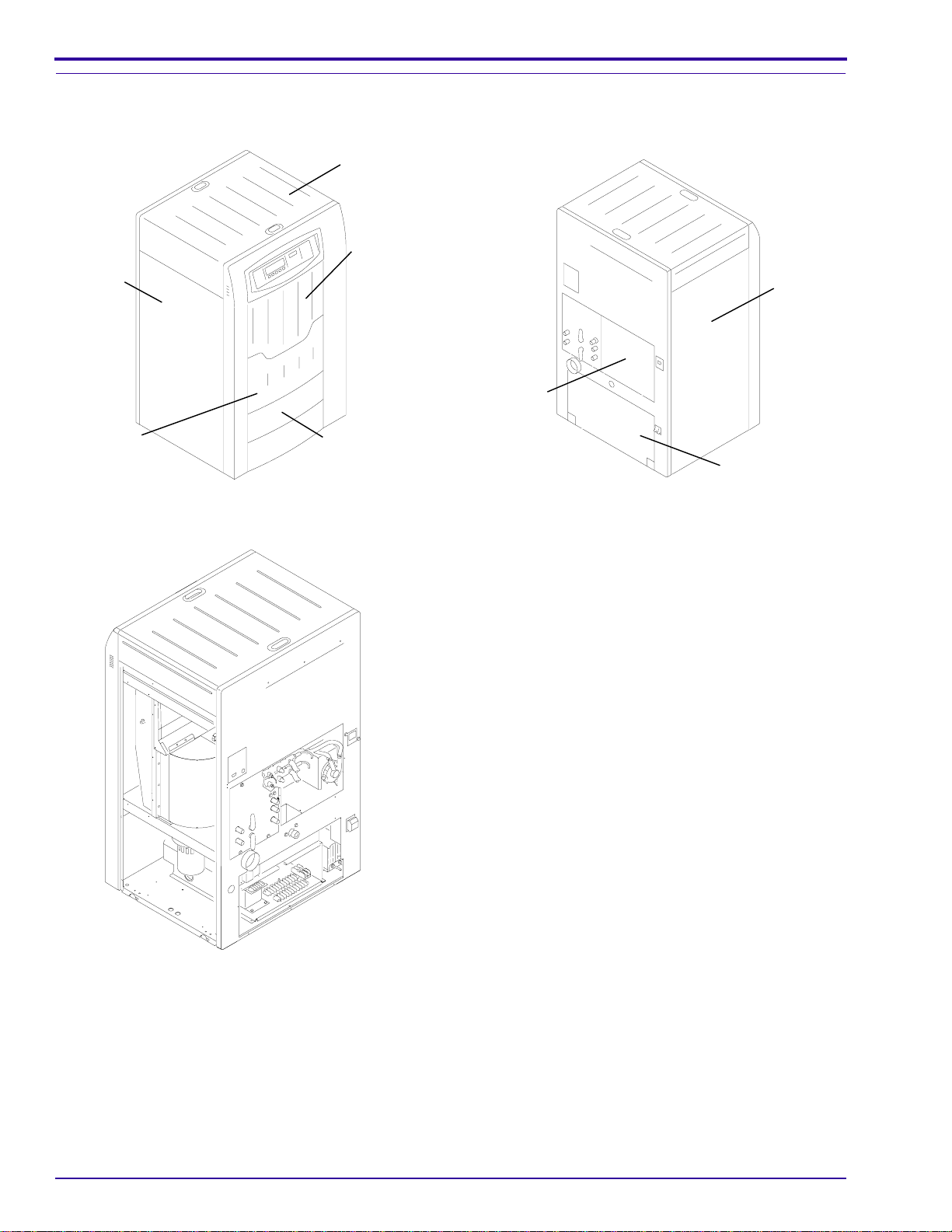
Preparing the PROCESSOR for Installation . . . . . . . . . . . . . . . . . . . . . . . . . . . . . . . . . . . 5
Unpacking the PROCESSOR. . . . . . . . . . . . . . . . . . . . . . . . . . . . . . . . . . . . . . . . . . . 5
Removing the Packing Material . . . . . . . . . . . . . . . . . . . . . . . . . . . . . . . . . . . . 5
Removing the PROCESSOR from the PALLET . . . . . . . . . . . . . . . . . . . . . . . . 6
Removing the PANELS and Checking the Packing List . . . . . . . . . . . . . . . . . . 8
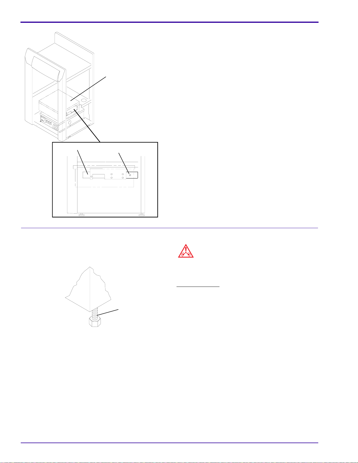
Removing the Packing Material from the DRYER and the SHIPPING SCREW 9
Installing the LEVELING SCREWS . . . . . . . . . . . . . . . . . . . . . . . . . . . . . . . . . . 10
Installing the PROCESSOR Through a Wall — Feed End. . . . . . . . . . . . . . . . . . . . . 11
Installing the PROCESSOR Through a Wall — Dryer End . . . . . . . . . . . . . . . . . . . . 12
Leveling the PROCESSOR . . . . . . . . . . . . . . . . . . . . . . . . . . . . . . . . . . . . . . . . . . . . 13
Installing the RACKS . . . . . . . . . . . . . . . . . . . . . . . . . . . . . . . . . . . . . . . . . . . . . . . . . 14
Installing the CROSSOVERS and the SQUEEGEE ASSEMBLY . . . . . . . . . . . . . . . 17
Connecting the PROCESSOR . . . . . . . . . . . . . . . . . . . . . . . . . . . . . . . . . . . . . . . . . . . . . 20
Making the Electrical Connections . . . . . . . . . . . . . . . . . . . . . . . . . . . . . . . . . . . . . . . 20
Connecting the JUMPERS at TB2 and TB3 and the Wires to TB1 . . . . . . . . . . 20
Connecting the Wires to TERMINAL STRIP TB1 . . . . . . . . . . . . . . . . . . . . . . . 22
Changing the PROCESSOR to 50 Hz Operation. . . . . . . . . . . . . . . . . . . . . . . . . . . . 28
Making the Plumbing Connections. . . . . . . . . . . . . . . . . . . . . . . . . . . . . . . . . . . . . . . 29
Installing the DEVELOPER FILTER . . . . . . . . . . . . . . . . . . . . . . . . . . . . . . . . . 29
Connecting the Drains . . . . . . . . . . . . . . . . . . . . . . . . . . . . . . . . . . . . . . . . . . . 29
Connecting the Water . . . . . . . . . . . . . . . . . . . . . . . . . . . . . . . . . . . . . . . . . . . . 30
Connecting the REPLENISHMENT TUBES . . . . . . . . . . . . . . . . . . . . . . . . . . . 31
Connecting the REPLENISHMENT TANKS . . . . . . . . . . . . . . . . . . . . . . . . . . . 31
Measuring the Static Pressure and Making the Exhaust Connections. . . . . . . . . . . . 32
Installing an AUXILIARY VENTILATION FAN KIT . . . . . . . . . . . . . . . . . . . . . . . . . . . 34
Installing and Adjusting the FEED TRAY . . . . . . . . . . . . . . . . . . . . . . . . . . . . . . . . . . . . . 35
Installing the FEED TRAY . . . . . . . . . . . . . . . . . . . . . . . . . . . . . . . . . . . . . . . . . . . . . 35
Adjusting the Height of the FEED TRAY . . . . . . . . . . . . . . . . . . . . . . . . . . . . . . . . . . 36
Aligning the FILM GUIDE . . . . . . . . . . . . . . . . . . . . . . . . . . . . . . . . . . . . . . . . . . . . . 36
Checking for the Correct Position of the LIGHT SHIELD . . . . . . . . . . . . . . . . . . . . . . 38
Checking the System . . . . . . . . . . . . . . . . . . . . . . . . . . . . . . . . . . . . . . . . . . . . . . . . . . . . 39
Checking for Leakage. . . . . . . . . . . . . . . . . . . . . . . . . . . . . . . . . . . . . . . . . . . . . . . . . 39
Checking Miscellaneous Components . . . . . . . . . . . . . . . . . . . . . . . . . . . . . . . . . . . . 40
Checking the DISPLAY PANEL . . . . . . . . . . . . . . . . . . . . . . . . . . . . . . . . . . . . . . . . . 40
Checking the Transport . . . . . . . . . . . . . . . . . . . . . . . . . . . . . . . . . . . . . . . . . . . . . . . 40
Final Steps . . . . . . . . . . . . . . . . . . . . . . . . . . . . . . . . . . . . . . . . . . . . . . . . . . . . . . . . . . . . 41
Publication History . . . . . . . . . . . . . . . . . . . . . . . . . . . . . . . . . . . . . . . . . . . . . . . . . . . . . . . 42

INSTALLATION INSTRUCTIONS
4 January 1996 – 5B6339
Section 1: General Information
Electrostatic Discharge
Overview ESD — electrostatic discharge — is a primary source of:
• product downtime
• lost productivity
• costly repairs
While one cannot feel a static charge of less than 3,500 volts, as few as 30 volts can damage or destroy
essential components in electronic equipment.
Preventive Measures
• Always look for an ESD warning label before doing any procedure involving static-sensitive
components such as CIRCUIT BOARDS. All static-sensitive components are marked with bright
graphic labels, which frequently include instructions. Follow all label instructions.
• Wear a grounding strap when handling static-sensitive components. Always make certain that the
clip remains attached to a properly grounded, unpainted, clean surface.
• Repair static-sensitive components at an ESD-protected work station or use a portable grounding
mat. For help in setting up an ESD-protected work station, contact your Kodak representative.
• When moving static-sensitive components from one area to another, insert and transport the
components in ESD-protective packaging. Transparent antistatic bags are available from a variety
of manufacturers and will help shield components from ESD damage.
Special Tools Required
Tool No. Description
TL-1434 12-in. BENCH LEVEL
TL-2431 AIR METER

Preparing the PROCESSOR for Installation
5B6339 – January 1996 5
Section 2: Preparing the PROCESSOR for Installation
Unpacking the PROCESSOR
Removing the Packing Material
Note
If you are unpacking the PROCESSOR anywhere other than the installation site, either install all removed parts or
pack them carefully with the PROCESSOR for transport.
[1] Check the shock-indicator labels on the shipping carton for possible damage in shipping.
[2] Cut the bands around the outside of the shipping carton.
[3] Open the top of the shipping carton, and remove the cardboard and the PREPACK items that are above the
PROCESSOR.
[4] Remove:
a. shipping carton from the PROCESSOR
b. tape and corner PROTECTORS
c. TOP COVER from the PROCESSOR
d. CROSSOVERS
e. SQUEEGEE ASSEMBLY
H148_0009BA
H148_0009BCA
DETECTOR
CROSSOVER
DEVELOPER/FIXER
CROSSOVER SQUEEGEE
ASSEMBLY
FIXER/WASH
CROSSOVER

INSTALLATION INSTRUCTIONS
6 January 1996 – 5B6339
[5] Remove the RACKS and the plastic packing material.
Removing the PROCESSOR from the PALLET
Warning
• The PROCESSOR weighs over 227 kg (500 lb).
Use 2 persons when installing the LEVELING
SCREWS and moving the PROCESSOR into
position.
• The PROCESSOR is not fastened to the PALLET.
Be careful when moving the PALLET.
[1] Move the PROCESSOR, on the PALLET, as close
as possible to the installation site.
Note
The following steps are for moving the PROCESSOR
off the drive side of the PALLET, but if access is easier
on the nondrive side of the PROCESSOR, remove the
BOLTS and RAIL from the nondrive side of the
PALLET.
[2] Move the PROCESSOR toward the nondrive side
until the nondrive side of the PROCESSOR is
flush with the nondrive edge of the PALLET.
[3] Remove the 2 BOLTS and the RAIL that is under
the drive side of the PALLET.
H148_0010BA
WASH RACK
FIXER RACK
DEVELOPER RACK
H148_0010BCB
H148_0175GA
H148_0175GCA
side
drive
side
nondrive
RAIL
PALLET
2 BOLTS
TOP COVER

Preparing the PROCESSOR for Installation
5B6339 – January 1996 7
[4] Carefully move the PROCESSOR to the center of
the PALLET.
[5] Carefully tilt the PROCESSOR and PALLET
toward the drive side until the other person can
place the RAIL under the nondrive side RAIL of
the PALLET. See the figure.
[6] Continue to tilt and move the PROCESSOR to
remove the PROCESSOR from the PALLET.
H148_0176CA
drive
side
nondrive
side
H148_0176CCA
RAILS
PALLET

INSTALLATION INSTRUCTIONS
8 January 1996 – 5B6339
Removing the PANELS and Checking the Packing List
DRYER END of the PROCESSOR Feed End of the PROCESSOR
[1] Remove:
• RECEIVING BIN
• 2 side ACCESS PANELS
• DRYER ACCESS PANELS
• ELECTRICAL BOX ACCESS PANEL
• MIDDLE ACCESS PANEL
• TRANSFORMER ACCESS PANEL
[2] Remove the items packed behind the drive side
ACCESS PANEL.
[3] Use the Packing List to check that all the items on
the List were shipped with the PROCESSOR.
H148_0181AA
H148_0181ACA
PANEL
BOX ACCESS
ELECTRICAL
TOP
COVER
DRYER
ACCESS
PANEL
RECEIVING
BIN
nondrive
ACCESS
PANEL
side
H148_0182AA
H148_0182ACA
PANEL
ACCESS
MIDDLE
ACCESS PANEL
TRANSFORMER
PANEL
ACCESS
side
nondrive
H148_0188GA
drive side

Preparing the PROCESSOR for Installation
5B6339 – January 1996 9
Removing the Packing Material from the DRYER and the SHIPPING SCREW
[1] Remove the packing material that holds the ends of the ROLLER ASSEMBLIES and AIR TUBES.
[2] Remove the front AIR TUBES and all the ROLLERS from the DRYER.
[3] Remove all the remaining packing material from the DRYER.
[4] Check that the back AIR TUBES are fully seated on both the drive and nondrive sides.
[5] Install the ROLLERS and front AIR TUBES.
[6] Check that the ROLLERS and the front AIR TUBES are fully seated on both the drive and nondrive sides.
H148_0116HA
H148_0116HCA ASSEMBLY
ROLLER
AIR TUBE

INSTALLATION INSTRUCTIONS
10 January 1996 – 5B6339
[7] Remove the SHIPPING SCREW from the drive
side ELECTRICAL BOX SLIDE.
[8] Remove the tape from the ELECTRICAL BOX.
Installing the LEVELING SCREWS
Caution
Tilting the PROCESSOR from front to back may cause
damage to the PANELS of the PROCESSOR. To
install the LEVELING SCREWS, tilt the PROCESSOR
from side to side.
[1] Tilt the PROCESSOR to the drive side, and install
the 2 nondrive side LEVELING SCREWS.
[2] Rotate the LEVELING SCREWS fully up.
[3] Tilt the PROCESSOR to the nondrive side and
install the other 2 LEVELING SCREWS, and
rotate fully up.
H148_0177GA
drive side
H148_0177GCA
SCREW
SHIPPING
SLIDE
BOX
ELECTRICAL
H148_0184AA
H148_0184ACA
SCREW
LEVELING

Preparing the PROCESSOR for Installation
5B6339 – January 1996 11
Installing the PROCESSOR Through a Wall — Feed End
Note
• For Dryer End installation through the wall, see
Page 12.
• The customer is responsible for preparing a hole in
the wall of the correct size to install the
PROCESSOR. Refer to the Site Specifications,
Publication Part No. 5B6338
Caution
Do not stretch the LIGHTTIGHT GASKET.
[1] Install the self-adhesive LIGHTTIGHT GASKET
onto the feed end of the PROCESSOR.
(a) Cut strips of GASKET for the 3 edges of the
PROCESSOR. See the figures.
(b) Cut 2 strips of GASKET for the top and
bottom of the BAR.
[2] Move the PROCESSOR within approximately
2.5 cm (1 in.) of the wall.
[3] Install the 4 FLOOR PLATES under the
4 LEVELING SCREWS. FLOOR PLATES are
availableforthe3/8-in.LEVELINGSCREWSonly.
If installing a SEISMIC KIT, use the FLOOR
PLATES provided with the SEISMIC KIT.
[4] Check that the LIGHTTIGHT GASKET is tight
against the wall. Compress the LIGHTTIGHT
GASKET to approximately 10 mm (3/8 in.).
[5] Wait to place the BAR under the PROCESSOR
until after you level the PROCESSOR on Page 13.
[6] Checkforlightleakagearoundthe PROCESSOR,
then advance to Page 13.
2.5 cm
(1.0 in.)
H148_0034CA
H148_0034CCA
GASKET
LIGHTTIGHT
BAR
GASKET
LIGHTTIGHT
BAR
PLATE
FLOOR
LEVELING SCREW
WALL
PROCESSOR
GASKET
TIGHT
LIGHT
H148_0035AA
H148_0035ACA
BAR
LIGHTLOCK
GASKET
LIGHTTIGHT
PANEL
WALL

INSTALLATION INSTRUCTIONS
12 January 1996 – 5B6339
Installing the PROCESSOR Through a Wall — Dryer End
Note
• See Page 11 for Feed End installation through the
wall.
• The customer is responsible for preparing a hole in
the wall of the correct size to install the
PROCESSOR. Refer to the Site Specifications,
Publication Part No. 5B6338.
• For Dryer End installation through the wall, order
Kodak X-Omat
THROUGH-THE-WALL LIGHT-
LOCK KIT, CAT No. 898 0815.
Caution
Do not stretch the LIGHTTIGHT GASKET.
[1] Install the self-adhesive LIGHTTIGHT GASKET
onto the ANGLE BRACKETS.
(a) Cut strips of GASKET for each of the
3 edges of the ANGLE BRACKETS. See
the figure.
(b) Cut 2 strips of GASKET for the top and
bottom of the BAR.
[2] Attach the ANGLE BRACKETS to the wall.
[3] Move the PROCESSOR within approximately
2.5 cm (1 in.) of the wall.
[4] Install the 4 FLOOR PLATES under the
4 LEVELING SCREWS. FLOOR PLATES are
availableforthe3/8-in.LEVELINGSCREWSonly.
If installing a SEISMIC KIT, use the FLOOR
PLATES provided with the SEISMIC KIT.
[5] If you are also installing a
Kodak
5000 RA
INTEGRATED CHEMICAL MIXER, install it now.
See the Installation Instructions in the Service
Manual for the MIXER, Publication Part
No. 5B6727.
[6] Level the PROCESSOR. See Page 13.
[7] Adjust the ANGLE BRACKETS until the
LIGHTTIGHT GASKET is compressed against
the PROCESSOR to approximately 10 mm
(3/8 in.).
[8] Tighten the 9 SCREWS.
[9] Check that the LIGHTTIGHT GASKET is tight
against the PROCESSOR.
[10] Place the BAR under the PROCESSOR.
[11] Check for light leakage around the PROCESSOR.
H148_0078CA
BAR
GASKET
LIGHTTIGHT
BAR
PLATE
FLOOR
LEVELING SCREW
PROCESSOR
GASKET
LIGHTTIGHT
LIGHT-
TIGHT
GASKET
ANGLE BRACKET
H148_0078CCA
H148_0077AA
H148_0077ACA
BAR
GASKET
LIGHTTIGHT
BRACKETS
ANGLE
PANEL
WALL

Preparing the PROCESSOR for Installation
5B6339 – January 1996 13
Leveling the PROCESSOR
Leveling the PROCESSOR from Side to Side
[1] Place a LEVEL TL-1434 as shown in the figure at
the left.
[2] Adjust the LEVELING SCREWS to level the
PROCESSOR from side to side.
Caution
To prevent damage to the LEVELING SCREWS and
the PROCESSOR, do not allow more than a 2.5 cm
(1 in.) clearance between the bottom of the
PROCESSOR and the HEAD of the LEVELING
SCREW.
[3] Placea LEVEL asshownin thefigure belowatthe
left. Adjust the LEVELING SCREWS to level the
PROCESSOR from front to back.
Leveling the PROCESSOR from Front to Back
H148_0017GA
H148_0017GCA
LEVEL
H148_0018GA
H148_0018GCA
LEVEL
H048_0141AC
2.5 cm (1 in.)
LEVELING
SCREW
FLOOR
PLATE HEAD
H048_0141ACA

INSTALLATION INSTRUCTIONS
14 January 1996 – 5B6339
Installing the RACKS
[1] Unwrap the items removed during the unpacking
procedure.
[2] Check that:
• DEVELOPER HEAT EXCHANGER COVER
is correctly seated in the bottom of the
DEVELOPER TANK
• DEVELOPER HEAT EXCHANGER COVER
is pressed completely down
[3] Install:
• DEVELOPER RACK
• FIXER RACK
• WASH RACK
H148_0016CA
H148_0016CCA
EXCHANGER
HEAT
COVER
EXCHANGER
HEAT
DEVELOPER
TANK
DEVELOPER
H148_0010BA
WASH RACK
FIXER RACK
DEVELOPER RACK
H148_0010BCB

Preparing the PROCESSOR for Installation
5B6339 – January 1996 15
Checking the GEARS
[4] Check that the RACKS are in the correct positions and are seated correctly.
[5] Check that the GEARS of the RACKS engage the GEARS of the MAIN DRIVE SHAFT.
[6] If necessary for local codes, install a SEISMIC KIT. Use SEISMIC KIT 8B6812 for 3/8-in. LEVELING SCREWS
or SEISMIC KIT 8B7038 for 1/2-in. LEVELING SCREWS. Each SEISMIC KIT includes all parts necessary to
install the BRACKETS on one PROCESSOR
H148_0019BA
H148_0019BCA
SHAFT
DRIVE
MAIN
GEAR
RACK
on a
GEAR

INSTALLATION INSTRUCTIONS
16 January 1996 – 5B6339
Installing the SEISMIC BRACKETS
H148_0163EA
3/8-in. Leveling Screw and Seismic Kit
1/2-in. Leveling Screw and Seismic Kit
H148_0163ECB
BOLT
WASHER
SEISMIC
BRACKET
NUT
LEVELING SCREW
1/2 in. WASHER BOLT
BRACKET
SEISMIC
PLATE
FLOOR
SEISMIC
PLATE
FLOOR
SCREW
LEVELING
3/8 in.

Preparing the PROCESSOR for Installation
5B6339 – January 1996 17
Installing the CROSSOVERS and the SQUEEGEE ASSEMBLY
Important
To prevent water from mixing with the processing chemicals, both ends of the WATER TROUGH must be in the
notches in the SIDEPLATES.
[1] Check that the 2 WATER TROUGHS are installed correctly on the FIXER/WASH CROSSOVER and the
DEVELOPER/FIXER CROSSOVER. Both ends of the WATER TROUGH must be in the notches in the
SIDEPLATES.
TO
INSTALL
TO
REMOVE
CORRECT
H148_0037DA
H148_0037DCB
notch
notch
WATER
TROUGH
TROUGH
WATER notch
TROUGH
WATER

INSTALLATION INSTRUCTIONS
18 January 1996 – 5B6339
[2] Install:
• DEVELOPER/FIXER CROSSOVER
• FIXER/WASH CROSSOVER
• DETECTOR CROSSOVER
• SQUEEGEE ASSEMBLY
[3] Check that the CROSSOVERS and SQUEEGEE ASSEMBLY are fuly seated.
[4] Install the YOKE between the DEVELOPER/FIXER and FIXER/WASH CROSSOVERS on the nondrive end of
the CROSSOVERS. See the figure below and the one on Page 19.
H148_0009BA
H148_0009BCA
DETECTOR
CROSSOVER
DEVELOPER/FIXER
CROSSOVER SQUEEGEE
ASSEMBLY
FIXER/WASH
CROSSOVER
H148_0130BA
H148_0130BCA
VALVE
DISCONNECT
QUICK
CROSSOVER
FIXER/WASH
CROSSOVER
FIXER
DEVELOPER/
YOKE

Preparing the PROCESSOR for Installation
5B6339 – January 1996 19
[5] Install the 2 EVAPORATION COVERS on the DEVELOPER/FIXER and FIXER/WASH CROSSOVERS.
[6] Check that the EVAPORATION COVERS are correctly seated, with correct clearance on the nondrive side for
the YOKE.
FIXER
DEV
H148_0187HA
H148_0187HCB
ASSEMBLY
SQUEEGEE
RACK
WASH
CROSSOVER
FIXER/WASH
RACK
FIXER
CROSSOVER
FIXER
DEVELOPER/
RACK
DEVELOPER
CROSSOVER
DETECTOR
COVERS
EVAPORATION
YOKE
CLEANING
CROSSOVER

INSTALLATION INSTRUCTIONS
20 January 1996 – 5B6339
Section 3: Connecting the PROCESSOR
Making the Electrical Connections
Connecting the JUMPERS at TB2 and TB3 and the Wires to TB1
[1] Extend the ELECTRICAL BOX.
[2] Remove the COMPONENT PLATE COVER.
[3] Determine the supply voltage to be applied to the
PROCESSOR.
[4] Install the correct ELECTRIC SERVICE LABEL
from the PREPACK onto the DATA PLATE.
H148_0183AA
H148_0183ACA
COVER
PLATE
COMPONENT
BOX
ELECTRICAL
KODAK
X-OMAT 5000 RA Processor
SERVICE
CODE SERIAL
NUMBER
3425
LISTED 115B
Made in USA by
Eastman Kodak Company
Rochester, New York 14650
H148_0185CA
apply ELECTRIC
SERVICE LABEL here
DATA
PLATE
H148_0185CCA
Other manuals for X-Omat 5000 RA PROCESSOR
2
Table of contents
Other Kodak Laboratory Equipment manuals

Kodak
Kodak X-Omat M43 PROCESSOR User manual

Kodak
Kodak DryView 8900 User manual

Kodak
Kodak DryView 8100 User manual

Kodak
Kodak X-Omat MULTILOADER 300 Plus User manual

Kodak
Kodak X-Omat 2000 User manual

Kodak
Kodak X-Omat MULTILOADER 300 User manual

Kodak
Kodak Dryview 5800 User guide

Kodak
Kodak Dryview 5800 User manual

Kodak
Kodak CARESTREAM DRYVIEW 5850 User manual

Kodak
Kodak X-Omat 460 RA Processor User manual