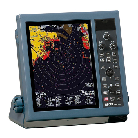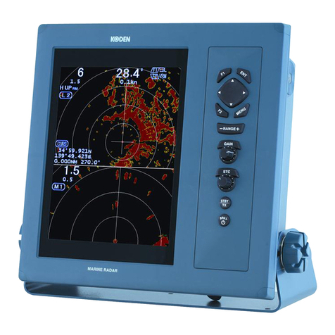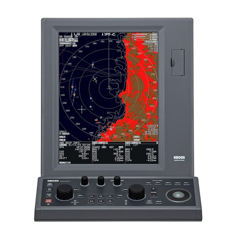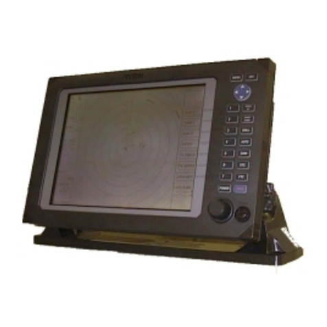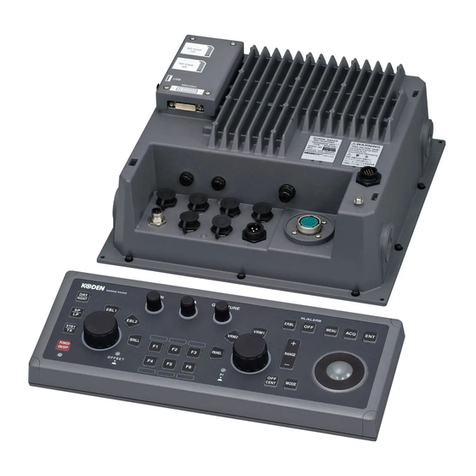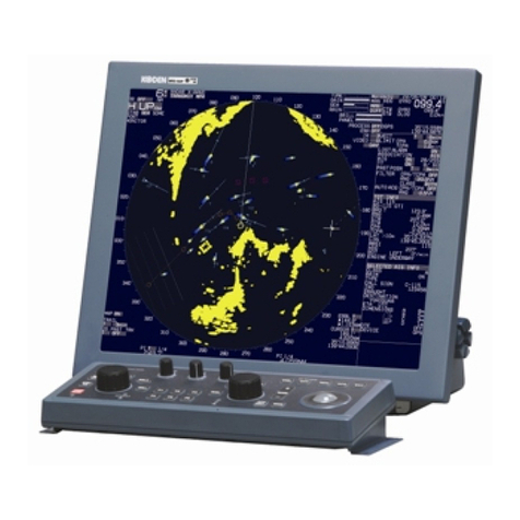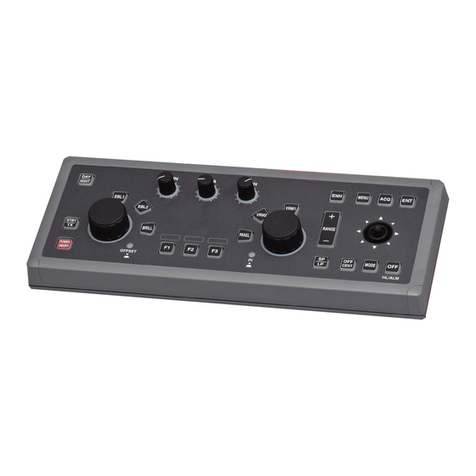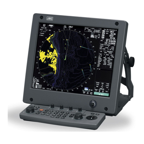
A table of content MDC-2900 Series
ii 0092629012-00
3.4.6 AIS cable connection................................................................................................ 3-14
3.4.7 Cable connection for NAV, EPFS and SDME or Log................................................ 3-15
3.4.8 Cable connection for interswitch............................................................................... 3-16
Chapter 4 Setup after installation................................................................................................ 4-1
4.1 Display [STARTUP] menu......................................................................................... 4-1
4.2 Set up antenna installation height from sea level...................................................... 4-1
4.3 Setup antenna cable length ...................................................................................... 4-1
4.4 Adjustment of automatic tune................................................................................ 4-2
4.5 Adjustment of transmitting delay time (Trigger Delay) ................................................... 4-2
4.6 Display bearing adjustment ........................................................................................... 4-2
4.7 Setup of MBS value (Main Bang Suppression) ............................................................. 4-3
4.8 Setup own ship profile (Cannot use while transmitting) ................................................. 4-3
4.9 MON (performance monitor).......................................................................................... 4-4
4.11 Setup Interface ............................................................................................................4-5
4.11.1 Select Heading interfaces......................................................................................... 4-5
4.11.2 Speed interfaces....................................................................................................... 4-6
4.11.2.1 Setup speed through water (STW) ........................................................................ 4-6
4.11.2.2 Select speed over ground (SOG) interface............................................................ 4-6
4.11.2.3 Select SET/DRIFT input ........................................................................................ 4-7
4.11.3 Select POSITION interface....................................................................................... 4-7
4.12 Setup TIME............................................................................................................... 4-7
4.13. Setup of Output .......................................................................................................... 4-8
4.13.1 Alarm output .............................................................................................................4-8
4.14 Change of maximum adjustable range of [GAIN] knob ............................................. 4-8
4.15 Adjustment of SEA AUTO ............................................................................................ 4-8
4.16 Change of adjustment range of manual [SEA] knob ................................................. 4-9
4.16.1 Change of maximum value of [SEA] knob................................................................ 4-9
4.16.2 Change of minimum value of [SEA] knob................................................................. 4-9
4.17 Change of adjustment range of [CFAR] knob .............................................................. 4-9
4.17.1 Change of maximum value for suppression effect of [CFAR] knob .......................... 4-9
4.17.2 Change of minimum value of [CFAR] knob .............................................................. 4-9
4.18 Change of signal detection level of TT.................................................................... 4-10
4.19 Change of background noise and target signal gradation....................................... 4-10
4.19.1 Change of background noise ................................................................................. 4-10
4.19.2 Change of Signal gradation.................................................................................... 4-10
4.20 F (Function key) usage ............................................................................................4-11
Chapter 5 Troubleshooting and on-board repair ......................................................................... 5-1
5.1 Necessary information at the time requesting repairs.................................................... 5-1
5.2 Provided self diagnostic facilities ................................................................................... 5-1
