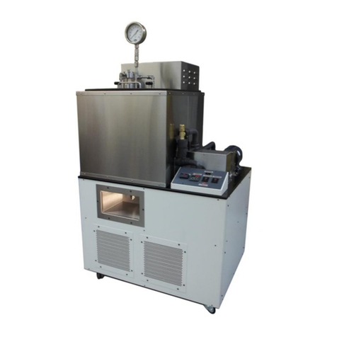
Koehler K71000 Guide

Operation and Instruction Manual
REV A
Koehler Instrument Company, Inc.
1595 Sycamore Avenue • Bohemia, New York 11716-1796 • USA
Toll Free: 1-800-878-9070 (US only) • Tel: +1 631 589 3800 • Fax: +1 631 589 3815
http://www.koehlerinstrument.com • e-mail: info@koehlerinstrument.com
Petroleum Testing & Analysis Instrumentation • Custom Design & Manufacturing
K71000
Automatic PMCC Flash Point Analyzer


K71000 Automatic PMCC Flash Point Analyzer
Operation and Instruction Manual
K710XX-Manual -1-
WEEE Directive Compliance Statement
Background
The goal of the WEEE Directive is to encourage design of environment-friendly products that increase
reuse, recycling and other forms of recovery to reduce waste streams and applies to listed Electronic and
Electrical Equipment (EEE) and Koehler's equipment falls broadly into Appendix 1A; Section 9 Monitoring
and Control Equipment: Measuring, weighing or adjusting appliances for household or as laboratory
equipment.
Any associated non-embedded equipment such as Lighting (Saybolt Color) and PCs/Printers also fall
under WEEE. If provided with an order these ancillary items must be WEEE compliant. For these and
other reasons (printer cartridges are regionalized) the equipment must be supplied through a third party
supplier in Europe.
The WEEE Directive applies to electrical and electronic equipment falling under the categories set out in
Annex IA provided that the equipment concerned is not part of another type of equipment that does not
fall within the scope of this Directive. Annex IB contains a list of products which fall under the categories
set out in Annex IA.
http://eur-lex.europa.eu/LexUriServ/LexUriServ.do?uri=OJ:L:2003:037:0024:0038:en:PDF
We do not qualify for any of the 10 exemption categories.
http://www.dpa-system.dk/en/WEEE/Products/Exemptions
Professional use
For equipment defined for ’professional use’ local authorities have no role to play. Producers and
importers are basically responsible for collection of WEEE recyclables from the professional user and for
subsequent management. A separate statement is given cataloging the items that require separation
from the equipment along with basic information on subsequent processing or recycling prior to disposal
of the equipment.
http://www.dpa-system.dk/en/WEEE/Products/Private-or-professional-use
Responsibility for Registration and Annual Reporting:
Koehler will not sell directly to end users in the EU and so has no responsibility to register within each EU
state and to make annual reports. Koehler declares that this responsibility is born by the importer who is
the first level of the distribution chain and is subject to producer responsibility. We will communicate this
in writing to our distributor/importers in the EU stating they are responsible to satisfy WEEE registration
and reporting requirements in the EU states where they conduct sales activities.
It is illegal to market electrical and electronic equipment covered by producer responsibility without being
registered.
http://www.dpa-system.dk/en/WEEE/Producers/Whoissubjecttoproducerresponsibility
Product Design
Koehler's designs allow for complete disassembly to a modular level which usually allows for standard
recycling. A qualified refrigeration system technician must be consulted when disassembling and de-
commissioning any equipment with refrigeration systems.
Koehler's scientific testing equipment is robustly designed to function over a long service life and are
typically repaired many times over the course of years rather than being replaced. We believe that re-use
and refurbishment is the very best form of re-cycling.
All batteries must be readily removable not soldered in place.
Recycling instructions
In the event that replacement becomes necessary, we will include instructions, particularized to each
instrument that informs the customer of their recycling responsibilities and giving them guidance in doing

K71000 Automatic PMCC Flash Point Analyzer
Operation and Instruction Manual
K710XX-Manual -2-
this. All Koehler equipment has been placed on the market since 13th August 2005 and so Koehler is
defined as a "new WEEE producer". As such we must provide information on refurbishment, treatment,
and re-use.
Our instrument manual will include this compliance statement and indicate that any collection of materials
will be handled by their authorized distributor. In the event that the distributor is unreachable or is no
longer a distributor for Koehler Instrument, Co., other arrangements may be made including accepting the
materials directly.
Recycling is free of charge. Shipping is the responsibility of the end users. Whether shipping to a
distributor or to Koehler directly, safe, properly declared, and labeled packaging and shipping expenses
are the sole responsibility of the end user.
WEEE Marking
Since Koehler products are subject to the WEEE Directive we must display the WEEE symbol shown
above in accordance with European Standard EN 50419 on the equipment. It must be indelible, at least
5mm in height, and clearly legible. If the equipment is too small the mark must be in the product literature,
guarantee certificate, or on the packaging. Rules on marking are established in section 49 of the WEEE
Order.
Koehler Instrument Company, Inc.
c/o RECYCLING
1595 Sycamore, Ave.
Bohemia, NY 11716
As a minimum the following substances, preparations and components have to be removed from any
separately collected WEEE:
- Mercury containing components, such as switches or backlighting lamps (compact fluorescent lamps,
CFL),
- Batteries
- Printed circuit boards if the surface of the printed circuit board is greater than 10 square centimeters
(about 4 sq in.),
- Toner cartridges, liquid and pasty, as well as color toner,
- Chlorofluorocarbons (CFC), hydrochlorofluorocarbons (HCFC) or hydrofluorocarbons (HFC),
hydrocarbons (HC)
- Liquid crystal displays (together with their casing where appropriate) of a surface greater than 100
square centimeters and all those back-lighted with gas discharge lamps,
- External electric cables
- Components containing refractory ceramic fibers as described in Commission Directive 97/69/EC of 5
December 1997 adapting to technical progress Council Directive 67/548/EEC relating to the classification,
packaging and labeling of dangerous substances (2),
- Electrolyte capacitors containing substances of concern (height > 25 mm, diameter > 25 mm or
proportionately similar volume)
2. The following components of WEEE that is separately collected have to be treated as indicated:
- Equipment containing gases that are ozone depleting or have a global warming potential (GWP) above
15, such as those contained in foams and refrigeration circuits: the gases must be properly extracted and
properly treated. Ozone-depleting gases must be treated in accordance with Regulation (EC) No
2037/2000 of the European Parliament and of the Council of 29 June 2000 on substances that deplete
the ozone layer (4).

K71000 Automatic PMCC Flash Point Analyzer
Operation and Instruction Manual
K710XX-Manual -3-
Table of Contents
Intellectual Property............................................................................................................4
Liability.................................................................................................................................4
1Introduction....................................................................................................................5
1.1 Koehler's Commitment to Our Customers .............................................................................................5
1.2 Recommended Resources and Publications......................................................................................... 5
1.3 Pensky-Martens Flash Point Method Scope and Summary..................................................................6
1.4 Instrument Specifications....................................................................................................................... 7
2Safety Information and Warnings.................................................................................8
2.1 Safety Considerations............................................................................................................................8
2.2 Unit Design.............................................................................................................................................8
2.3 Contaminated Samples.......................................................................................................................... 9
2.4 Safe Quick Test Method......................................................................................................................... 9
2.5Fire Detection / Suppression and Draft Shield / Dome System............................................................. 9
2.6 Equipment Modification and Replacement Parts................................................................................... 9
2.7 Chemical Reagents Information............................................................................................................. 9
2.8 Additional Important Safety Information................................................................................................. 9
2.9 Other Important Hazards......................................................................................................................10
3Getting Started.............................................................................................................10
3.1 Packing List..........................................................................................................................................10
3.2 Unpacking ............................................................................................................................................11
3.3 Setup....................................................................................................................................................11
4Descriptions.................................................................................................................13
4.1 Front of Instrument............................................................................................................................... 13
4.2 Back of Instrument...............................................................................................................................15
4.3 Cover Assembly..................................................................................................................................17
5Operation......................................................................................................................18
7Service..........................................................................................................................37
8Storage .........................................................................................................................37
9Warranty .......................................................................................................................37
10 Returned Goods Policy ...............................................................................................37
Notes..................................................................................................................................38

K71000 Automatic PMCC Flash Point Analyzer
Operation and Instruction Manual
K710XX-Manual -4-
Intellectual Property
This manual and the K71000 are protected by Copyright. Reproduction by any manner is prohibited.
Excerpts by permission only. All rights reserved.
All brand names and product names otherwise mentioned are trademarks or registered by their
respective companies or organizations.
Liability
This manual was competently reviewed prior to issue, however, no express or implied liability whatsoever
is assumed for losses or consequential damages or losses arising from the use information contained in
or omitted from this manual.
Koehler Instrument Co. assumes no liability for losses arising from the negligent or improper use of our
equipment nor for losses arising from the improper use or use other than intended. Only deliberate action
or gross negligence are grounds for any claim.
Due care has been exercised in the development of the software program controlling this instrument,
however, Koehler Instrument Co. assumes no liability nor makes any guarantee for any consequences
arising from the use of the program. We explicitly, and above all, disclaim any guarantee of economic
success, missed earnings, consequential damages and deficiently consequential damages.
Neither the computer software provided, nor can the operating system software, nor can the underlying
integrated circuits function flawlessly under any usual or unusual set of operating conditions due to
limitations in the current state of software and hardware engineering.

K71000 Automatic PMCC Flash Point Analyzer
Operation and Instruction Manual
K71000-Manual -5-
1 Introduction
The Koehler model K71000 Automated
Pensky-Martens Closed Cup Flash Point
Analyzer is the latest design for performing the
ASTM D93 test method and related test
specifications.
The K71000 determines the flash points of
distillate fuels (diesel, biodiesel blends,
kersosene, heating oil, turbine fuels), new and
in-use lubricating oils, residual fuel oils, cutback
residua, used lubricating oils, mixtures of,
petroleum liquids containing suspended solids
and petroleum liquids that tend to form a surface
film during testing and biodiesel (B100). It
determines the flash points of a wide range of
products by a closed cup method with stirring of
the sample.
This manual provides important information
regarding safety, technical reference, installation
requirements, operating condition specifications,
user facility resource requirements, and
operating instructions for the K71000 Automated
Pensky-Martens Closed Cup Flash Point
Analyzer. This manual should also be used in
conjunction with applicable published laboratory
procedures. Information on these procedures is
given in section 1.2.
1.1 Koehler's Commitment to Our
Customers
Providing quality testing instrumentation and
technical support services for research and
testing laboratories has been our specialty for
more than 50 years. At Koehler, the primary
focus of our business is providing you with the
full support of your laboratory testing needs.
Our products are backed by our staff of
technically knowledgeable, trained specialists
who are experienced in both petroleum products
testing and instrument service to better
understand your requirements and provide you
with the best solutions. You can depend on
Koehler for a full range of accurate and reliable
instrumentation as well as support for your
laboratory testing programs. Please do not
hesitate to contact us at any time with your
inquiries about equipment, tests, or technical
support.
Toll Free: 1-800-878-9070 (US only)
Tel: +1 631 589 3800
Fax: +1 631 589 3815
e-mail: info@koehlerinstrument.com
http://www.koehlerinstrument.com
1.2 Recommended Resources and
Publications
1. American Society for Testing and Materials
(ASTM)
100 Barr Harbor Drive
West Conshohocken, Pennsylvania 19428-
2959, USA
Tel: +1 610 832 9500
Fax: +1 610 832 9555
http://www.astm.org
email: service@astm.org
ASTM Publication:
ASTM D93: Flash Point by Pensky-
Martens Flash Point Tester
2. International Organization for
Standardization (ISO)
1, rue de Varembé
Case postale 56
CH-1211 Geneva 20, Switzerland
Tel: 41 22 749 01 11
Fax: 41 22 733 34 30
http://www.iso.org
ISO Publication:
ISO 2719: Petroleum Products and
Lubricants - Determination of Flash Point -
Pensky-Martens Closed Cup Method
3. Energy Institute (IP)
61 New Cavendish Street
London, WIM 8AR, United Kingdom
Tel: 44 (0)20 7467 7100
Fax: 44 (0)20 7255 1472
http://www.energyinstpubs.org.uk/
IP Publication:
IP 34: Determination of closed flash point
–Pensky-Martens method
4. Deutsche International Norm (DIN)
http://www.din.de
DIN Publication:
DIN 51758: Testing of liquid petroleum
products and other combustible liquids;
determination of flash point by Pensky-
Martens closed tester

K71000 Automatic PMCC Flash Point Analyzer
Operation and Instruction Manual
K71000-Manual -6-
DIN EN 22719: Petroleum products and
lubricants; determination of flash point;
Pensky-Martens closed cup method
(withdrawn)
5. Federal Test Method (FTM)
FTM Publication:
FTM 791-1102: Flash Point by Pensky-
Martens Closed Tester
6. American Association of State Highway and
Transportation Officials (AASHTO)
444 North Capitol Street N.W., Suite 249
Washington, DC 20001
Phone: +1 202 624-5800
Fax: +1 202 624-5806
E-mail: info@aashto.org
AASHTO Publication:
AASHTO T73-811
7. Association Française de Normalisation
(AFNOR)
http://www.afnor.fr
AFNOR Publication:
NF M 07-019
8. Japanese Industrial Standards(JIS)
http://www.jisc.go.jp
JIS Publication:
JIS K2265
1.3 Pensky-Martens Flash Point Method
Scope and Summary
The K71000 Automatic Pensky-Martens Flash
Point Analyzer determines the lowest flash point
temperature of fuels, lubricating oils, and
homogenous liquids (ASTM D93 A), or liquids
containing suspended solids as well as liquids
that tend to form a surface film during testing
(ASTM D93 B), and the determination of the
flash point of biodiesel in the temperature range
of 60 to 190°C (ASTM D93 C).
Method Scope:
The scope of the method covers the analysis of
products in the temperature range of 40 to
360°C but this automated apparatus extends the
range from dew point + 10°C to 400°C.
Internet Link to Summary: ASTM D93 PM Flash
Standard Method Scope and Summary
Method Summary:
Flash Point is the lowest temperature
(barometrically corrected to standard
atmospheric pressure of 101.3 kPa (760 Torr) at
which the vapors of a combustible liquid will
ignite and the flame front propagate across the
head-space of the sample cup under the
conditions specified by the test method.
Flash point tests are conducted by filling the test
cup to the full indication mark, placing the flash
cup into the test sample chamber then locking
the cup cover into position.
Next, the user selects a predefined or user
programmed test method, types in or accepts
the expected flash point (EFP), optionally
selects a product type, then hits the start button.
A Quick Test feature allows for determination of
flash points of unknown materials beginning the
test from ambient and proceeding with the test
at an accelerated heating rate.
The unit is equipped with a differential Pt-100
RTD probe designed to duplicate the response
time of a mercury-in-glass thermometer as per
ASTM D93-02a and E1-03a. If a flash is not
detected 30°C above the expected flash point or
at 405°C, then the test is automatically aborted
for safety.

K71000 Automatic PMCC Flash Point Analyzer
Operation and Instruction Manual
K71000-Manual -7-
Once analysis is complete the results are
displayed to the screen and saved to the
instrument hard disk drive. The results may be
opened in a report generation program like MS
Word or Excel and sent to a local or network
printer. Once the results have been reviewed
and accepted by the operator the results may be
sent directly to a network folder for processing
and direct entry into LIMS.
Once analysis is complete the instrument
actuates the rapid cool-down system. The cool-
down system is capable of reducing the
temperature of the sample from 300 to 30°C in
about 8 minutes in a laboratory with ambient
conditions at 20°C. User can also manually
switch to standard air cooling. Cooling the
system will take a longer period of time however
fan noise will be reduced.
1.4 Instrument Specifications
Models:
K71000
Electrical
Requirements:
115/230VAC 50/60Hz
User selectable via switch
located at the back of the
analyzer
Temperature
Measuring Range:
Ambient to 405°C (761°F)
Flash Detection
System:
Differential
Thermocouple,
Ionization Detection
Stirring Speed:
0 to 300 RPM
Heating Rate:
In accordance to ASTM
D93 procedure A, B, C
Quick Test (≈12°C/min)
Ignition Source:
Gas and Electric Igniter
both equipped on cover
assembly:
- Software Selectable
- User-Friendly Manual
Switching
Mechanical Lift:
Three (3) position
mechanical lift system of
cover / motor assembly,
software selectable:
Open –Clean –Test
Cleaning:
Cover / Motor assembly
lift features convenient
cleaning position. At this
position the user can
easily remove the cover
assembly and clean with
appropriate solvent
between tests.
Ignition Test
Frequency:
User selectable on per
method basis
Cooling:
Integrated Dual Fan
System: First (1) directly
to cup, Second (2) to cool
environment around test
cup
Barometric
Pressure
Correction:
Automatic Barometric
Pressure Transducer for
Flash Temperature
Correction
Interface Port:
RS232:1
USB:2 (1–Front, 1–Back)
Ethernet:1 (LIMS)
Gas Supply /
Connection:
Ignition Gas: LP Gas
(Propane / Butane) or
Natural Gas.
Min. 3.45kPa (0.5psi).
Max. 6.90kPa (1.0psi)
Display:
8.4" LCD Touch Screen
Temperature
Sensor:
PT-100 in S/S sheath,
User
Programmable
Methods & Data
Storage:
Capable of storing
unlimited data runs and
test methods

K71000 Automatic PMCC Flash Point Analyzer
Operation and Instruction Manual
K71000-Manual -8-
Temperature
Calibration:
Three (3) Types
available:
- 2 Point Sample
Temperature (Standard)
- Multipoint (>2)
Temperature Calibration
(Available as Option)
- CRM Calibration –Built-
In Software function to
automatically correct as
per CRM tested
Security:
Three level password
protection
Key Safety
Features:
- Collision / Interference
Detection: Analyzer can
sense user position
around moveable parts
and stop its motion
- Fire suppression
detection: Equipped with
second gas line for
connection to CO2or
Nitrogen gas. Gas
disbursement ring around
test cup/cover saturated
area with extinguishing
gases.
Ambient
Temperature
Range:
10 to 35°C
Altitude:
Rated for use below
2000m
Environmental
Conditions:
As per section 1.4.1 of
IEC 61010
Dimensions:
(in.(cm))
Width: 10 7/8” (27.63cm)
Depth: 17.5” (44.45cm)
Height:
- Closed Test Position –
20” (50.8cm)
- Fully Open Position –
26” (66.04cm)
Net Weight:
60 lbs (27.22 kg)
2 Safety Information and Warnings
2.1 Safety Considerations
The most important safety consideration is that
people are operating this piece of equipment.
The laboratory staff and management are
responsible to assure that only authorized,
trained and competent personnel use this
equipment.
The use of this equipment may involve
hazardous materials and operations. This
manual does not purport to address all of the
safety problems associated with the use of this
equipment. It is the responsibility of any user of
this equipment to investigate, research, and
establish appropriate safety and health practices
and determine the applicability of regulatory
limitations prior to use.
Test results from ASTM D93 flash point test are
used along with other data to assess the
flammable hazards of a material. By its very
nature a flash point analysis is the performance
of a hazardous activity (waving a flame above a
heated flammable material in the presence of
excess air) under carefully controlled conditions
(limited small amount of material, ability to
remove ignition source, ability to remove
oxidizer). Still there are conditions that can
cause operating problems during testing.
Among the most well known are samples
contaminated with water or light ends, and less
commonly, samples which foam and cause
overflow. Samples may also contain or be
contaminated with acutely toxic materials or
materials that when combusted pose a health
hazard.
2.2 Unit Design
This equipment is specifically designed for use
in accordance with the applicable standard test
methods listed in section 1.2 of this manual. The
use of this equipment in accordance with any
other test procedures, or for any other purpose,
is not recommended and may be extremely
hazardous.
WARNING: The K71000 Automatic
Pensky-Martens Flash Point Analyzer was
designed to be the safest flash point instrument
in the marketplace, however, there are safety
concerns and hazards, which this instrument is
not designed to address. The purchase and

K71000 Automatic PMCC Flash Point Analyzer
Operation and Instruction Manual
K71000-Manual -9-
acceptance of this instrument signifies that the
purchasing company and their agents, the end
users, are responsible for establishing all safety
and health practices and assumes full
responsibility for safely using the K71000
Automatic PMCC Flash Point Analyzer.
2.3 Contaminated Samples
Samples contaminated with light ends (highly
volatile petroleum products) may light and
continue burning when the expected flash point
is set above the fire point of the material. In
addition, burning material may be ejected
through the ignition aperture in the test cup
cover. For this reason, the most recent updates
to ASTM D93 require a first application of
ignition at ambient temperature (<24°C below
EFP) and every 10°C. This helps when the
contaminant flashes at room temperature but
does not address all contamination situations.
Samples contaminated with water can bump and
eject hot and flammable material from the test
cup.
At all times, refrain from leaning or bending over
the test cup when the test is being carried out.
An unexpected flash can cause serious injury to
exposed body parts that are in close proximity to
the test area. Ejected material may cause
serious harm.
2.4 Safe Quick Test Method
The K71000 has a quick test option that begins
testing at ambient then heats the sample at an
accelerated pace while applying the igniter at
3°C increments. The detected flash is an
estimate of the expected flash point which is
then used in a subsequent run (under prescribed
standard test conditions) to safely arrive at the
flash point. The only disadvantage of this
screening method is that it requires additional
time and material to complete a safe analysis.
The Maximum Quick Test Temperature is 370
°C.
NOTE: The user must set this prescribed end
point prior to running a quick test. The set
maximum run temperature is solely at the user's
discretion.
We recommend this method of screening for
ALL samples.
2.5 Fire Detection / Suppression and Draft
Shield / Dome System
The K71000 comes standard with a fire
detection and inert gas fire suppression system.
This system is designed to flood the sample cup
area with an inert gas, extinguishing sample
based fires. The system is triggered when a
high temperature event melts the thermal fuse.
The open circuit condition triggers the flame
suppression system. The electronics are
extremely fast relying solely on electronic logic
(no software). The flame suppression system
also shuts off the ignition gas source, closes the
cup cover by de-energizing the motor, and de-
energizes the electric igniter if in use.
WARNING: Never operate the instrument
without the draft shield make it difficult to
inadvertently touch hot working surfaces.
2.6 Equipment Modification and
Replacement Parts
Any modification or alteration of this equipment
from that of factory specifications is not
recommended and voids the manufacturer
warranty, product safety, performance
specifications, and/or certifications whether
specified or implied, and may result in personal
injury and/or property loss. Replacement parts
must be O.E.M. exact replacement equipment.
2.7 Chemical Reagents Information
Chemicals and reagents used in performing the
test may exhibit potential hazards. Any user
must be familiarized with the possible dangers
before use. We also recommend consulting the
Material Data and Safety Sheet (MSDS) on each
chemical reagent for additional information.
MSDS information can be easily located on the
internet at http://siri.uvm.edu or
http://www.sigma-aldrich.com.
2.8 Additional Important Safety Information
WARNING: As an important safety
precaution, NEVER use unregulated gas with
the K71000 Pensky-Martens Closed Cup Flash
Point Analyzer!
Use in an area that is adequately ventilated,
preferably with an exhaust tube / pipe to remove

K71000 Automatic PMCC Flash Point Analyzer
Operation and Instruction Manual
K71000-Manual -10-
any fumes that may be emitted during the test.
Conduct tests behind a safety shield, especially
if you are not sure of the flash point or the
ignition temperature. Wear appropriate personal
protective equipment (PPE) during testing.
NOTE: ASTM D93 specifically notes that
a hood should not be operated during testing as
excessive drafts can cause erroneous results!
Exercise caution in removing and replacing the
cup in the furnace. Hot surfaces and substances
may cause injury if they come in contact with the
operator.
All connections should be properly made and
tested for leaks prior to carrying out the tests.
The ignition gas source should be equipped with
a proper safety regulator capable of delivering a
maximum of 5 psi of pressure to the test flame
assembly. Some propane regulators give
pressure in inches of water (inH20) at 60°F. A
standard 11 inches of water (inH20) regulator
should give sufficient gas for normal use.
Minimum pressure required is about 7 kPa or
1.0 psi.
The flame suppression (inert gas) source should
be regulated to between 20 and 30 psi for safe
use.
2.9 Other Important Hazards
Working surfaces on the instrument may
become hot enough to produce severe burns
even with momentary contact.
Open flames and electrically heated resistance
elements are present. Direct momentary
contact can cause severe burns.
The draft shield around the sample area also
functions as a mechanical guard. The
instrument should never be used if this guard is
removed.
WARNING: Electrical hazards exist inside
the instrument case. Lethal voltages and
current are present. Only factory authorized or
otherwise qualified personnel may repair or
service this instrument. Only original parts may
be used for repair. No substitution parts or
alterations to this equipment are allowed; doing
so may void the warranty.
PC Motherboard WARNINGS
- Due to high voltages inside the instrument,
under no circumstances should the instrument
be opened or access covers removed while
energized.
- Lethal voltages are present inside power
supplies. Under no circumstances should
Power Supply covers be removed. Power
Supply warranties are voided once the cover
is removed.
- For indoor use only. Please operate the
power supply in a safe and dry environment.
- Do not insert any objects into the open
ventilation or fan grill area of the power supply.
3 Getting Started
The instructions for preparing the equipment
assume that the user is aware of the contents of
this document, which lists the warranty
conditions and important precautions.
3.1 Packing List
K71000 Automatic PMCC Flash Point
Analyzer, 115/230V 50/60Hz
Brass Test Cup with Handle
Combination Gas/Electric Igniter
Stirrer Shaft and Blade Assembly
PT-100 Temperature Probe / Thermal
Detector
Ionization Detector
Cover Assembly
Draft Shield
Stylus
Temperature Calibration Cable
Power Cords, 115V & 230V
K71000-Manual K71000 Automatic PMCC
Flash Point Analyzer Operation and
Instruction Manual
Installed in the K71000
Panel PC and Microprocessor Controllers
Operating Software, Instruction Manual
PDF, Recovery Software on Hard Disk Drive
Thermocouple and Ionization Detection
Fire Sensing and Suppression System
Collision / Interference Detection
Mechanical Lift System
Dual Fan Cooling System

K71000 Automatic PMCC Flash Point Analyzer
Operation and Instruction Manual
K71000-Manual -11-
On Outside of Instrument
Identification Plate
- Model Number
- Serial Number
- Voltage / Hz / Phase / Amp
- Company Contact Information
Optional Accessories (purchased
separately):
Calibration Decade Box
Stainless Steel Test Cup
USB Printer
Certified Reference Material
3.2 Unpacking
1. Check Shock Watch Label on Cardboard
Box for indication of rough handling and
possible damage.
2. Check labeling for correct orientation of
instrument. (e.g. This Side Up)
3. Carefully open top of box with box cutter and
remove packing foam.
4. Make two additional vertical cuts, using box
cutter, along length of two sides of the box
and remove packing foam.
5. Extract instrument and place on suitable cart
for transportation to work area / lab bench.
WARNING: Be sure two or more
individuals are available for extracting and lifting
instrument from box to cart and from cart to
bench. Individuals must lift in accordance to
proper technique. See accompanying figure.
6. Lift instrument from cart and place on bench.
7. Ensure that all parts listed on the packing list
are present. Inspect the unit and all
accessories for damage. If any damage is
found, keep all packing materials and
immediately report the damage to the
carrier. We will assist you with your claim, if
requested. When submitting a claim for
shipping damage, request that the carrier
inspect the shipping container and
equipment. Do not return goods to Koehler
without written authorization.
3.3 Setup
Equipment Placement: Make sure the
instrument in placed on a firm, level table in an
area with adequate ventilation or in a hood. The
unit may be leveled by making minor turning
adjustments to the feet located at the base of
the unit. Please note that Koehler does not
supply a level with this equipment.
The instruments dimensions are:
Width: 10 7/8” (27.63cm)
Depth: 17.5” (44.45cm)
Height:
- Closed Test Position –20” (50.8cm)
- Fully Open Position –26” (66.04cm)
For proper operation the instrument requires
adequate ventilation.
It is recommended that approximately 15 cm
(6 inches) of space be provided on either
side of the instrument. This recommendation
is dependent upon the lab environment and
samples typically run. Samples with a
higher flash point require increasing the
heater temperature to high values.
About 15 cm (6 inches) clearance is
required behind the instrument for
connecting gasses and utilities.
The instrument is on feet and draws air from
the bottom, exhausting to the top and sides.
The bottom must not be obstructed. Dust
must not be allowed to accumulate beneath
the instrument.
Environmental Conditions: The instrument
environment must comply with the following
conditions for proper setup:
No / Low Dust
NOTE: Electronics lifetime may be
reduced due to heat build-up resulting from
dust contamination

K71000 Automatic PMCC Flash Point Analyzer
Operation and Instruction Manual
K71000-Manual -12-
Distilled fuel must be wiped off of instrument
work surfaces and not be allowed to collect.
This is a flammability hazard and collects
dust.
Free of Corrosive Fumes
No Direct Sunlight
Not near heating or AC ventilation ducts
No Vibrations
Clearance from other instruments so as to
not influence instruments ambient conditions
Height of bench top must allow for easy
viewing and use
Temperature Range:15 to 35°C (59 to 95°F)
Maximum Rate of Change: 6°C (10°F) / hr
Elevation to 2000 meters
Relative Humidity: < 80%, non-condensing
NOTE: No warranty provision is made to
cover instrument failure due to environmental
conditions outside the above mentioned criteria.
No warranty is provided that the instrument will
produce acceptable results outside the above
mentioned criteria.
Ventilation. A fume hood or exhaust system is
required after performing a test. Flammable
vapors and/or steam are generated during
operation and must not be permitted to
accumulate. A canopy-style hood may be used if
the height from the top of the unit to the canopy
is 5 feet or less. The exhaust blower should
have a rating of 1000 C.F.M. or greater.
Power: Connect the line cords to properly fused
and grounded receptacles with the correct
voltage as indicated in section 1.3 or on the
back of the unit. A switch located on the back of
the unit allows the user to switch the input
voltage to either 115VAC or 230VAC.
WARNING: Ensure the voltage type
selected on the back of the unit matches the
plug type used when powering the instrument.
WARNING: For safety, disconnect the
power when performing any maintenance and/or
cleaning. Do NOT turn the power on unless the
bath is filled with the proper medium; otherwise,
damage may occur to the unit and the warranty
will be void.

K71000 Automatic PMCC Flash Point Analyzer
Operation and Instruction Manual
K71000-Manual -13-
4 Descriptions
4.1 Front of Instrument
Figure 1: Instrument Descriptions_Front

K71000 Automatic PMCC Flash Point Analyzer
Operation and Instruction Manual
K71000-Manual -14-
1. Power Button: This button allows the user to turn the instrument on and off from the front side. The
main power switch at the back of the unit (Figure 2, Item 12) must be switched ON prior to pressing
on the power button.
2. Emergency Fire Suppression Button: Pressing this button initiates the integrated Fire Suppression
System. While depressed, turning the button clockwise will release button and reset.
NOTE: Inert Gas must be connected to secondary gas port located at the back of the
instrument for fire suppression system to function properly.
3. USB Connection Port: For connection of USB device to export test results, save software
screenshots and upload factory software updates.
4. Touch Screen Control Panel: Main control point of instrument. Please refer to section _._ for full
operational details.
5. Leveling Feet: To make adjustments to instrument level for proper operation.
6. Ignitor Flame Adjustment Knob: Controls gas flow to ignitor Flame for fine tuning flame size in
accordance to test method.
7. Pilot Flame Adjustment Knob: Control gas flow to pilot flame for fine tuning pilot flame size. Pilot
flame is designed to ensure ignitor flame remains lit during entire testing procedure.
8. Ignitor Connection Port: For connection of gas / electric ignitor assembly to instrument
9. Spill Guard: To prevent sample from spilling or leaking on Touch Screen Control Panel
10. Draft Shield: Provides user protection from test area. Protects test flame from external draft source
11. Test Cup: Brass test cup equipped with heat resistant handle. Test cup locks in place for sample
stabilization during testing.

K71000 Automatic PMCC Flash Point Analyzer
Operation and Instruction Manual
K71000-Manual -15-
4.2 Back of Instrument
Figure 2: Instrument Descriptions_Back

K71000 Automatic PMCC Flash Point Analyzer
Operation and Instruction Manual
K71000-Manual -16-
12. Power Switch: Controls power to the entire unit. To power on the instrument, first press the Power
Switch to ON then press the Power Button (Figure 1, Item 1) on the front on the analyzer.
13. AC Outlet: The analyzer has been designed with an integrated C13 line socket in order to easily
change plug types (115V or 230V). Internal voltage can be switch using the Voltage switch (Figure 2,
Item 19).
14. Cooling Fan: Integrated cooling fan is capable of operating at two speed for either standard or rapid
cooling. The user may change the fan speed using the touch screen control panel.
15. USB Port: For connection to Keyboard or Mouse.
16. RS232 Port: For connection to external PC
17. Ethernet Port: For connection to LIMS system.
18. CPU Port: For programming of internal CPU. FOR FACTORY USE ONLY
19. Voltage Switch: The user may easily switch the internal voltage compatibility by switching up or
down. The voltage type will be displayed on the switch accordingly.
20. Inert Gas Inlet: For connection of external inert gas source, typically Nitrogen. Analyzer must be
connected to gas source for the integrated Fire Extinguishing System to be utilized properly.
21. LPG or Natural Gas Inlet: For connection to Natural Gas Source or Bottled Gas (LPG - Propane or
Butane is typically used).
22. Barometric Pressure Sensor: Point where internal automatic barometric pressure adjustment
system senses atmospheric pressure. No user function.

K71000 Automatic PMCC Flash Point Analyzer
Operation and Instruction Manual
K71000-Manual -17-
4.3 Cover Assembly
Figure 3: Instrument Descriptions_Cover Assembly
23. Stirring Propeller: To maintain sample homogeneity throughout the duration of the test.
24. Sample Temperature Probe: Measures sample temperature during testing.
25. Ionization Detector: For automatic detection of the sample's flash point.
26. Flame Detection Thermocouple: For continuous monitoring of pilot flame during testing. In the
event the test flame goes out, the Flame detection thermocouple will automatically detect this and
initiate re-lighting of the flame.
27. Pilot Flame: The pilot flame ensures the test flame is lit prior to each test dip.
28. Electric Ignitor: Alternative means for applying heat source to initiate a flash point. The electric
ignitor is also used to light the pilot flame.
29. Gas Ignitor: Referee means for applying heat source to initiate a flash point.
30. Application Mechanism: Houses gas / electric ignitor assembly. Automatically lowers ignitor into
test cup at intervals in accordance to the prescribed test method.
31. Electric Ignitor Cable: Reinforced cable for connecting to Ignitor Connection Port (Figure 1, Item 8).
32. Gas Tubing: Provides means for gas source to reach gas ignitor.

K71000 Automatic PMCC Flash Point Analyzer
Operation and Instruction Manual
K71000-Manual -18-
5 Operation
1. User Login - Upon turning on the instrument the user will be prompted to select the desired user log
in level. There are four levels to choose from. Factory preset pass codes for Levels 1, 2, and 3 are
listed below:
Level 1 –1234
Level 2 –2345
Level 3 –3
Levels 1, 2, and 3 can be custom configured by pressing the Set Access Priorities Key. The fourth or
factory level is designed for administrative purposes only and specifically allows for access to the
factory settings menu. From this screen, the user can also Change User Password, Set Access
Priorities, Turn off Security and Contact Koehler.
Figure 4: User Login Screen
2. Change User Password - Clicking on the Change User Password button will bring up a screen that
will allow the user to change the password of any of the four user levels. Choose the desired user
level by clicking on the Select User Level pull down tab. Then type in the Current Password for that
level, the New Password, then click Save.
Table of contents
Other Koehler Measuring Instrument manuals
Popular Measuring Instrument manuals by other brands

GEM
GEM 1230 Installation, operating and maintenance instructions

Triplett
Triplett 630 instruction manual

Geotech
Geotech EcoSense pH100A user manual

Konica Minolta
Konica Minolta CA-410 Series instruction manual

Oldham
Oldham OLCT 60 user manual

DRUCK & TEMPERATUR Leitenberger
DRUCK & TEMPERATUR Leitenberger LR-Cal LTC 100 manual