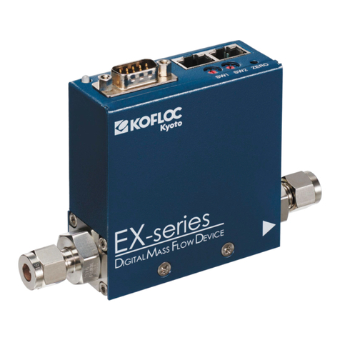
Kofloc 8700 Series User manual

MJ400307A1
1
Thermal Mass Flow Meter / Controller
MODEL 8700 SERIES
RS-485 Communications Instruction Manual

MJ400307A1
2
Table of Contents
Page
1. Foreword 3
2. RS-485 Communi ation Spe ifi ations 3
3. Example of Conne tion 4
4. How to Enable the RS485 Communi ation Terminator 5
5. List of Communi ation Commands and Addresses 6-14
6. Operation-Confirmed Converter for PC 14

MJ400307A1
3
1.Foreword
This do ument des ribes the spe ifi ations and operation of the RS-485
ommuni ations fun tion installed as a standard feature in Model 8700.
The wiring, installation and operating pro edures, other than ommuni ations, are
presented in a separate instru tion manual. Prior to use, please read it also.
2.RS-485 Communi ation Spe ifi ations
Item
Specifications
Synchronization
Start-stop
Transmission speed
9600bps
Frame structure
Start: 1 bit
Data length: 8 bits
Stop: 1 bit
Parity: None
Transmission system
Half duplex (3-wire type)
Insulation
Between communications – control circuit: Not insulated
Between communications – power supply (24 VDC): Not insulated
Setting of ID at shipment
01

MJ400307A1
4
3.Example of Conne tion
An example (referen e) of wire onne tion is shown below.
In the following example, the terminator is turned on in Communi ation ontroller Model
8700 (ID=n).
A
TR+
18PIN
TR-
19PIN
TR_COM
20PIN
Detail of pa
rt A
Max. 100m
Communi
a
tion
ontroller
Model 8700
ID=1
Model 8700
ID=2
Model 8700
ID=n
Max. 31 units

MJ400307A1
5
4.How to Enable the RS485 Communi ation Terminator
This equipment in orporates an RS485 terminator (120 Ω). When the
equipment is shipped, it has not been enabled. Where it is onsidered that
ommuni ations are disturbed by refle tive noise, et ., ondu t an operation to
enable the terminator as explained below.
Terminator
Swit h

MJ400307A1
6
5.List of Communi ation Commands and Addresses
◆Command messages
① Byte read
Command Checksum
02H
30H
30H
31H
52H
42H
31H
30H
30H
30H
03H
45H
42H
0DH
0AH
STX
0 0 1 R B 1 0 0 0 ETX
E B CR LF
Equipment ID Address
② Word read
Command Checksum
02H
30H
30H
31H
52H
44H
31H
30H
30H
30H
03H
45H
44H
0DH
0AH
STX
0 0 1 R D 1 0 0 0 ETX
E D CR LF
Equipment ID Address
③ Byte write
Command Separator
02H
30H
30H
31H
57H
42H
31H
30H
30H
30H
3AH
30H
30H
STX
0 0 1 W B 1 0 0 0 : 0 0
Equipment ID Address Write data
Checksum
03H
38H
41H
0DH
0AH
ETX
8 A CR LF
④ Word write
Command Separator
02H
30H
30H
31H
57H
44H
31H
30H
30H
30H
3AH
30H
30H
30H
30H
STX
0 0 1 W D 1 0 0 0 : 0 0 0 0
Equipment ID Address Write data
Checksum
03H
45H
43H
0DH
0AH
ETX
E C CR LF

MJ400307A1
7
◆Normal/abnormal response messages
① Byte read
Command Exit code
02H
30H
30H
31H
52H
42H
31H
30H
30H
30H
30H
30H
STX
0 0 1 R B 1 0 0 0 0 0
Equipment ID Address
Read data
2BH
30H
30H
03H
44H
36H
0DH
0AH
+ 0 0 ETX
D 6 CR LF
Sign Checksum
② Word read
Command Exit code
02H
30H
30H
31H
52H
44H
31H
30H
30H
30H
30H
30H
STX
0 0 1 R D 1 0 0 0 0 0
Equipment ID Address
Read data
2BH
30H
30H
30H
30H
03H
33H
38H
0DH
0AH
+ 0 0 0 0 ETX
3 8 CR LF
Sign Checksum
③ Byte write
Command Exit code
02H
30H
30H
31H
57H
42H
31H
30H
30H
30H
30H
30H
03H
35H
30H
STX
0 0 1 W B 1 0 0 0 0 0 ETX
5 0
Equipment ID Address Checksum
0DH
0AH
CR LF
④Word write
Command Exit code
02H
30H
30H
31H
57H
44H
31H
30H
30H
30H
30H
30H
03H
35H
32H
STX
0 0 1 W D 1 0 0 0 0 0 ETX
5 2
Equipment ID Address Checksum
0DH
0AH
CR LF

MJ400307A1
8
◆Detailed explanation
①STX
Indi ates the head of the message.
Fixed to 02H.
When STX is re eived, the equipment un onditionally judges it is the first letter of
the message.
②Equipment ID
Spe ify the destination equipment ID (1 – 127).
③Command
A ommand to the equipment.
RB … Data (byte) read
RD … Data (word) read
WB … Data (byte) write
WD … Data (word) write
④Address
Spe ify the head address of read/write data.
⑤Separator (Used only for writing)
A symbol to separate the address and data.
Fixed to 3AH.
⑥Exit ode (Response message only)
00 … Normal response
40 … Spe ifies a ommuni ation a ess disabled area
41 … Spe ifies an invalid item address
42 … Spe ifies an undefined ommand
⑦ETX
Indi ates that the previous part is the body of the message.
Fixed to 03H.
⑧Che ksum al ulation
Example: Data (word) write is used as an example for explanation.
①Message from STX to ETX added at every byte.
The lower 1 byte of the al ulation result is “ECH”.
②Converted to a hara ter ode.
Result “ECH” to (45H) and (43H).

MJ400307A1
9
⑨CR and LF
Indi ate the end of the message.
CR fixed “0DH” and LF fixed to “0AH”.
◆Data address
※Sin e EEPROM has a limit of the time of rewriting, use RAM if the rewriteing will be done
frequently, and use EEPROM if the data will be retained when the power is turned off.
※In ase of the rewriting to EEPROM, it will be refle ted in a tion when the power is turned
on again.
※There are invalid data for meter.
Communi ation Data RAM Address EEPROM Address
Basi mode data 1000 – 1029 4000 – 4029
Fun tion setting mode (set) data 1100 – 1121 4100 – 4121
Fun tion setting mode (parameter) data 1200 – 1247 4200 – 4247
Run set mode data 1300 4300
Integrated flow rate data 1400 – 1405 4400 – 4405
◆List of ommuni ation data
Meaning of symbols in R/W olumns: ○ … Possible, × …Not possible
① Basi mode data
Indi ation Data Range Size
RAM EEPROM
Add.
R
W
Add.
R
W
Instantaneous flow rate
-9999~9999 Word
1000
○
×
4000
×
×
SP No. being used
00:SP0
01:SP1
02:SP2
03:SP3
04:SP4
05:SP5
Byte
1002
○
○
4002
○
○
② Fun tion setting mode (set) data
Se tion with (d-xx) links to the list of fun tion setting mode in the instru tion manual.
Indi ation Data Range アクセス
サイズ
RAM EEPROM
Add.
R
W
Add.
R
W
Key lo k setting
(d-06)
00: No key lo k
01: Key lo k of settings other than flow
rate setting (SP)
02: Key lo k of all settings
Byte
1100
○
○
4100
○
○

MJ400307A1
10
Indi ation Data Range Size
RAM EEPROM
Add.
R
W
Add.
R
W
RUN key
a tion sele tion
(d-07)
00: RUN key not used
01: RUN key used
Byte
1101
○
○
4101
○
○
Flow rate
setting method sele tion
(d-01)
00: Digital setting
01: Analog setting
Byte
1102
○
○
4102
○
○
Event 1 output type
allo ation
(d-18)
00:Not used (normally off)
01:
On when integration flow rate event
o urs
02:On when flow rate is OK
03:On when operation mode =Control
04:
On when operation mode = Fully
opened
05: On when operation mode = Fully
losed
Byte
1104
○
○
4104
○
○
Event 2 output type
allo ation
(d-19)
00:Not used (normally off)
01:
On when integration flow rate event
o urs
02:On when flow rate is OK
03:On when operation mode =Control
04:
On when operation mode = Fully
opened
05: On when operation mode = Fully
losed
Byte
1105
○
○
4105
○
○

MJ400307A1
11
Indi ation Data Range RAM EEPROM
Add.
R
W
Add.
R
W
Flow rate alarm set type
0:Not used
1:Only upper limit alarm used
2: Only lower limit alarm used
3:Upper/lower alarms used
1109
○
○
4109
○
○
Sele tion of a tion when
alarm o urs
0:Control ontinue & alarm output
normally on
1:For ed fully losed & alarm output
normally on
1110
○
○
4110
○
○
Flow rate indi ation
referen e ondition sele tion
0:20℃, 1 atm
1:0℃, 1 atm
2:25℃, 1 atm
1112
○
○
4112
○
○
Dire t setting fun tion 0:No fun tion
1:Fun tion used
1113
○
○
4113
○
○
PV filter (instantaneous
flow rate averaging)
0:No PV filter
1:Moving average of sampling 2 times
2: Moving average of sampling 4 times
3: Moving average of sampling 8 times
4: Moving average of sampling 16 times
5: Moving average of sampling 32 times
1114
○
○
4114
○
○
Indi ation update y le
(Indi ator)
0:No update y le
1:50-mse y le
2:100-mse y le
3:200-mse y le
4:500-mse y le
5:1000-mse y le
1115
○
○
4115
○
○
PV (instantaneous flow
rate) for ed zero fun tion
0:No fun tion
1:Fun tion used
1116
○
○
4116
○
○
Equipment address 1~127
1117
1118
○
○
4117
4118
×
×
0-2% range indi ation
setting
0:0-2% flow rate indi ation
1:0 indi ation
1120
○
○
4120
○
○
PV (instantaneous flow
rate) indi ation de imal
point position fun tion
0:No de imal point (4321)
1:De imal point used (432.1)
2: De imal point used (43.21)
3: De imal point used (4.321)
1121
○
○
4121
○
○

MJ400307A1
12
③ Fun tion setting mode (parameter) data
Indi ation Data Range RAM EEPROM
Add.
R
W
Add.
R
W
Flow rate OK judgment
range 5~1000 (0.5%~100.0% FS)
1200
1201
○
○
4200
4201
○
○
Flow rate deviation upper
limit alarm value 5~1000 (0.5se ~100.0se )
1204
1205
○
○
4204
4205
○
○
Flow rate deviation lower
limit alarm value 5~1000 (0.5se ~100.0se )
1206
1207
○
○
4206
4207
○
○
Flow rate deviation alarm
judgment delay time 5~9999 (0.5se ~999.0se )
1208
1209
○
○
4208
4209
○
○
Event output 1 delay time 0~9999 (0.0se ~999.0se )
1210
1211
○
○
4210
4211
○
○
Event output 2 delay time 0~9999 (0.0se ~999.0se )
1212
1213
○
○
4212
4213
○
○
Integration event flow rate
(lower 4 digits) 0~9999
1216
1217
○
○
4216
4217
○
○
Integration event flow rate
(middle 4 digits) 0~9999
1218
1219
○
○
4218
4219
○
○
Integration event flow rate
(upper 4 digits) 0~9999
1220
1221
○
○
4220
4221
○
○

MJ400307A1
13
Indi ation Data Range RAM EEPROM
Add.
R
W
Add.
R
W
PV for ed zero fun tion
delay time 0~9999 (0.0se ~999.0se )
1222
1223
○
○
4222
4223
○
○
SP upper limit flow rate 0~1000 (0.0%~100.0% FS)
1224
1225
○
○
4224
4225
○
○
SP lower limit flow rate 0~1000 (0.0%~100.0% FS)
1226
1227
○
○
4226
4227
○
○
SP0 (Set flow rate) 0~1000 (0.0%~100.0% FS)
1228
1229
○
○
4228
4229
○
○
SP1 (Expanded set flow rate)
0~1000 (0.0%~100.0% FS)
1230
1231
○
○
4230
4231
○
○
SP2 (Expanded set flow rate)
0~1000 (0.0%~100.0% FS)
1232
1233
○
○
4232
4233
○
○
SP3 (Expanded set flow rate)
0~1000 (0.0%~100.0% FS)
1234
1235
○
○
4234
4235
○
○
SP4 (Expanded set flow rate)
0~1000 (0.0%~100.0% FS)
1236
1237
○
○
4236
4237
○
○
SP5 (Expanded set flow rate)
0~1000 (0.0%~100.0% FS)
1238
1239
○
○
4238
4239
○
○
SP8 (Analog set flow rate) 0~1000 (0.0%~100.0% FS)
1244
1245
○
×
4244
4245
×
×
Full s ale flow rate 100~1000
1246
1247
○
○
4246
4247
×
×
④ RUN set mode data
Indi ation Data Range RAM EEPROM
Add.
R
W
Add.
R
W
Operation mode
0:Valve fully opened
1:Valve ontrol
2:Valve fully losed
1300
○
○
4301
×
×

MJ400307A1
14
⑤ Integrated flow rate data
Indi ation Data Range RAM EEPROM
Add.
R
W
Add.
R
W
Integrated flow rate (lower
4 digits) 0~9999
1400
1401
○
×
4400
4401
×
×
Integrated flow rate (middle
4 digits) 0~9999
1402
1403
○
×
4402
4403
×
×
Integrated flow rate (upper
4 digits) 0~9999
1404
1405
○
×
4404
4405
×
×
6.Operation-Confirmed Converter for PC
Manufa turer Model
LINE EYE SI-35USB

MJ400307A1
15
URL:http://
www.kofloc.co.jp
Other manuals for 8700 Series
1
Table of contents
Other Kofloc Measuring Instrument manuals

Kofloc
Kofloc 8700 Series User manual

Kofloc
Kofloc RK20T Series User manual

Kofloc
Kofloc EX-700R User manual

Kofloc
Kofloc HFM-200 Series User manual

Kofloc
Kofloc EX-550 User manual

Kofloc
Kofloc FML300-D Series User manual

Kofloc
Kofloc DPM-3 User manual

Kofloc
Kofloc 3100 User manual

Kofloc
Kofloc EX-700R User manual

Kofloc
Kofloc FM01 Series User manual

Kofloc
Kofloc 3760 Series User manual

Kofloc
Kofloc FML-500 User manual

Kofloc
Kofloc 3810S User manual

Kofloc
Kofloc RK1975 Series User manual

Kofloc
Kofloc RK1812 Series User manual

Kofloc
Kofloc EX-250S User manual

Kofloc
Kofloc 3810DSII User manual

Kofloc
Kofloc HFM-301 Series User manual

Kofloc
Kofloc FM31 Series User manual