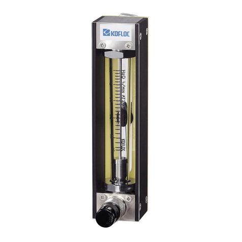
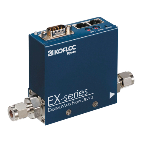
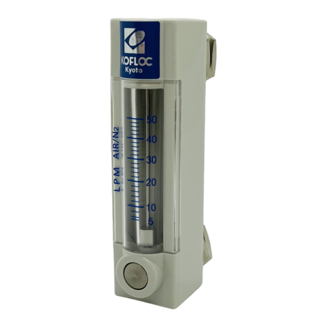
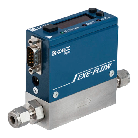
Kofloc EX-700R User manual

MJ400271F1
Mass Flow Meter with indicator
EX-700R
Instruction Manual

MJ400271F1
-
1
-
Ignoring this symbol and handling the
product incorrectly
may result in loss of life or serious injury.
Ignoring this symbol and handling the product incorrectly
may result in personal injury or damage to property.
Ԃ
〇
●

MJ400271F1
-
2
-
Table of Contents
1.Foreword ・・・・・・・・・・・・・・・・・・・・・・・・・・・・・・・・・
2.Precautions for Handling ・・・・・・・・・・・・・・・・・・・
3.Overview ・・・・・・・・・・・・・・・・・・・・・・・・・・・・・・・・
4.Standard Specifications ・・・・・・・・・・・・・・・・・・・・
5.ExternalView ・・・・・・・・・・・・・・・・・・・・・・・・・・・・・
6.Applicable Connectors and Pin Assignment・・・・・・
7.Operation ・・・・・・・・・・・・・・・・・・・・・・・・・・・・・・・・
8.Troubleshooting ・・・・・・・・・・・・・・・・・・・・・・・・・・
9.Precautions for maintenance ・・・・・・・・・・・・・・・・・
10. After-sale Service・・・・・・・・・・・・・・・・・・・・・・・・
11.Warranty ・・・・・・・・・・・・・・・・・・・・・・・・・・・・・・・・
3
3
7
8
9
13
14
22
23
23
23

MJ400271F1
-
3
-
1. Foreword
Thank you for your selection of the Digital Mass Flow Meter EX-700R.
Prior to using your new equipment, please read this manual thoroughly to ensure it is used in a safe manner.
Please keep in mind that this instruction manual may be revised without notice.
2. Precautions for Handling
◆Prior to use
All the products have been assembled and adjusted one by one in accordance with the specifications.
The type of gas to use, flow rate and other data are shown on the ID plate attached to the back of the case.
Check the ID plate and make sure these specifications meet your order.
・Date shown on the ID plate
① MODEL︓Model name-Use of Needle valve-Flow rate-Output
・Model name [EX-700R] : Mass Flow Meter
・Needle Valve [0]
[V]
: without needle valve
:
with n
eedle
valve
・Flow rate※[F1]10SCCM〜[F14]500SLM
・Output [I] : Current 4-20mA
※Flow range table
② GAS : Applicable gas
③ FLOW RATE
SCCM =ml/min (0℃1atm(101.325kPa))
SLM =l/min (0℃, 1atm(101.325kPa))
④ CALIB.: Calibration gas
⑤ PRESSURE : Supply pressure /Outlet pressure
⑥ SERIAL No.
◆
Main Body Block 25mm square
Code F1 F2 F3 F4 F5 F6 F7 F8
Flow rate 10SCCM 50SCCM 100SCCM 500SCCM 1SLM 5SLM 10SLM 20SLM
◆
Main Body Block 34mm square
Code F9 F10 F11
Flow rate 50SLM 100SLM 200SLM
◆
Main Body Block 40mm square
Code F12 F13 F14
Flow rate 300SLM 400SLM 500SLM

MJ400271F1
-
4
-
◆
)
◆
◆
①
②
③
④
⑤
⑥
⑦ ℃
µ
Ԃ
「」〜

MJ400271F1
-
5
-
?
℃

MJ400271F1
-
6
-
◆
Attension:X-700R and X-700(old model) are different adapter inputs.
◆
①
②
③ ℃
④
⑤
⑥

MJ400271F1
-
7
-
3. Overview
EX-700R is a mass flow meter equipped with an indicator that employs a proven flow sensor. It has a function
to indicate the integrated flow rate, in addition to the existing instantaneous flow rate indication.
A type with a flow sensor and precision needle valve in one unit is also available.
・The employment of a precision needle valve enables minute flow control and monitoring.
・Flow monitoring alarm 2 points output. (2 points each for any flow rate value)
・Instantaneous flow rate / analog output. (Voltage 0-5V or 1-5Vor Current 4-20mA), integrated flow rate / pulse
output installed.
・Compact and light weight.
・The flow meter is equipped with an indicator and can start measurement of flow rates as soon as a 24 VDC
power supply is connected.
・“Mass flow” enables direct reading of flow rates without a need of troublesome flow rate compensation
calculation by temperature/pressure.
3-1 Principle of operation
The flow detect sensor is designed with heating wire (resistance wire) wound around the outside of 2 point
of the metallic capillary.
When a gas flows through the capillary, it takes heat from the resistance wire in the upstream to cause its
temperature to drop. The heat in the upstream is transferred to the downstream, causing a deviation in the
resistance value. A difference in temperature in these two places is proportional to the flow rate of gas. The
difference in the resistance value caused by this temperature difference is converted to an electric signal to
indicate a flow rate.
The installation of a bypass capillary to bypass the flow to the sensor pipe restricts the flow of gas to the
sensor to enable the use in a wide range of flow rates.
The detected flow rate is indicated on the indicator and output as an electric signal from the terminals.

MJ400271F1
-
8
-
4. Standard Specifications
EX-700R
Flow range (N2conversion)
F.S.10SCCM〜20SLM F.S.50, 100, 200SLM F.S.300, 400, 500SLM
Accuracy*1
±1%F.S. ±1.5%F.S.
Applicable gas
*2 N2
(Air, H2, He, Ar, O2,
CO
2
,
CH
4
/By
N
2
conversion)
N2,(Air, Ar/
By N
2
conversion)
N2,(Air,/
By N
2
conversion)
Temperature
Accuracy guarantee
temperature
15〜35℃
Operating temperature
5〜50℃
Storage temperature
-10〜60℃
Operating humidity
10〜90%RH
(no condensation)
Pressure resistance
980kPa(G)
F
itting
(Standard)
1/4
SW
L
3/8
SW
L
1/2
SW
L
Materials of parts in contact with
gases
SUS316, SUS316L, PTFE, PCTFE
(only 300-500SLM)
, FKM (op.︓NBR, CR)
Power supply DC24V(±10%), 100mA or lower
Flow rate indication
Indicator
4-digit 7-segment LED (Zero blanking)
Instantaneous flow rate
indication update cycle
25, 50, 100, 200, 500, 1000msec
(selectable)
Low cut function
Indication of a value below 0.5% F.S. settable to “0”
Indication range
When the low cut -10% F.S. to approx. 125%
F.S. (indication limiter flashing)
Integrated flow rate
indication range
*
3
8-digit indication (Max. 99,999,999, indication limiter flashing)
The unitsofindicationarethesameasthe
instantaneousflow rate.
Digital communication RS485(MODBUS RTU),ID:1〜247
External output
Number of outputs
2 points (Each output selected and set to instantaneous flow rate upper limit,
lower limit, upper/lower limit or integrated flow rate reach. 1 point may be
integrating pulse.)
Inversion of outputs is possible.
Output method
NPN open collector (Max. rating: 30 VDC, 50 mA)
Integrating pulse output
rate
1%F.S.〜100%F.S. / pulse, pulse width: approx. 50ms
Alarm indication LED lamps (OUT1, OUT2) turning on
Analog output*4
Standard: 4-20mA (500Ωor below)
Switchable
:
1
-
5V or 0
-
5V (10k
Ω
or over)
Weight
Approx
. 600g
Approx
. 700g
Approx
. 1000g
Needle
valveparts
Flowadjustknobturning Approx.12turns
Materialsofpartsin
contactwithgases SUS316,PTFE,FKM(op.NBR,CR)
*1.
The accuracy is guaranteed for nitrogen gas.
*2. The full scale of the selected gas is the same as the full scale of N2.
*3.
The indication of integrated flow rates is for reference. It is held when the power is turned off.

MJ400271F1
-
9
-
◆〜
◆

MJ400271F1
-
10
-
◆

MJ400271F1
-
11
-
◆〜
◆

MJ400271F1
-
12
-
◆

MJ400271F1
-
13
-
:X-700R and X-700(old model) are different adapter inputs.
︓ ()
︓ ()

MJ400271F1
-
14
-
◆
◆
◆
JKJK
◆
◆□
【】
〇
Ă
ĂĂĂ
〇
・J
KJK
JK
・J
K

MJ400271F1
-
15
-
【】
〇
〇︓【】
【】
【】
◆ /
【】
〇
〇
【】︓ 〈〉〈〉
【】︓ 〈〉〈〉
【】
□JK
JK
□
□

MJ400271F1
-
16
-
①
□
→→Ă
②【】
□
□
□

MJ400271F1
-
17
-
7-5. 【Parameter setting mode】
When an instantaneous flow rate is being indicated, pressing and holding DISPkey [□] sets the parameter setting
mode. Each time DISP key [□] is pressed, the indication changes in the order of mode No. →set value →mode
No. →set value.
To change the set value, use the UP key [ ] or DOWN key [ ]. When the UP key [ ] or DOWN key [ ] is
pressed and held, the digit can be shifted.
After setting a parameter, pressing and holding DISP key [□] registers the set value and returns the mode to
the flow rate indication mode.
①Default values
A B C D
F-00 ※ ※ ※ ※
P-00 ※
P-01 1
P-02 3
P-03 3
P-04 0
P-05 0
P-10 0 0
P-11 9 9 9 9
P-12 9 9 9 9
P-13 3 0
P-14 9 9 9 9
P-15 9 9 9 9
P-16 0 1 0
P-20 0 0
P-21 9 9 9 9
P-22 9 9 9 9
P-23 3 0
P-24 9 9 9 9
P-25 9 9 9 9
P-26 0 1 0
P-30 1
P-31 1. 0 0 0
P-40 1
P-41 2
P-42 0
OUT2 instantaneous flow rate lower limit preset setting
OUT1 instantaneous flow rate lower limit preset setting
Dead time value
OUT1 integrated flow rate reach preset settingupper 4 digits
OUT1 integrated flow rate reach preset settinglower 4 dig-its
Integratingpulse output rate
Parity
Dead time value
Applicable gas selection
CF value
Communication ID
Integratingpulse output rate
Transmission speed selection
OUT2 integrated flow rate reach preset settingupper 4 digits
OUT2 integrated flow rate reach preset settinglower 4 dig-its
Low cut function selection
Mode No. Default Value Set Item
Indication of max. value (unchangeable)
Reference condition on flow rate
PVfilter
Instantaneous flow rate indication update cycle
Integrated flow rate hold selection
OUT1 output selection
OUT1 instantaneous flow rate upper limit preset setting
Analog output selection
OUT2 output selection
OUT2 instantaneous flow rate upper limit preset setting
※According to the ordered specifications.

MJ400271F1
-
18
-
②Setting mode No. and description of set values
Mode No. Set Item Default
Value
0: 20
℃
,1atm
1: 0
℃
,1atm
2: 25
℃
,1atm
0: Disable
1: Enable
0: No.
1: Movingaverage of sampling2 times
2: Movingaverage of sampling4 times
3: Movingaverage of sampling8 times
4: Movingaverage of sampling16 times
5: Movingaverage of sampling32 times
0: 25ms
1: 50ms
2: 100ms
3: 200ms
4: 500ms
5: 1000ms
0: disable
1: enable
Analogoutput
selection 0: 4-20mA
1: 0-5V
2: 1-5V
P-05 0
A B C D
0
Analogoutput
Description of set values
F-00 Indication of max.
value (Full scale) ※
A
B
C
D
2
0
0
0
The value of the full scale is indicated. Unchangeable. Max value :2000
P-00 Reference condition on
flow rate ※
A
B
C
D
0
Set the flow rate reference condition.
※The default values are as per the specifications.
Reference condition on flow rate
1
A
B
C
D
Low cut function selection (±0.5%F.S.)
P-01 Low cut function
selection
3
A
B
C
D
Input signals are measured duringthe period set here and an average value is calculated. Therefore, the
indication is averaged and updated at the set cycle.
1
0:Disable: Instantaneous flow rates below 0.5% F.S. are indicated. Negative values are also indicated.
1:Enable: Instantaneous flow rates below 0.5% F.S. are indicated as 0. Negative values are also
indicated as 0.
P-02 PV filter
0
PV filter
3
A
B
C
D
0
Instantaneous flow rate indication update cycle
1
A
B
C
D
0:Disable: The integrated flow rate value is reset when the power is turned off.
1:Enable: The integrated flow rate value is held after the power is turned off.
The integrated flow rate value hold cycle is 1 minute.
0
(The integrated flow rate value hold cycle :1min.)
Integrated flow rate hold
P-04 Integrated flow rate
hold selection
P-03 Instantaneous flow
rate indication update
cycle

MJ400271F1
-
19
-
Parameter
setting No.
Set Item Default
Value
P-16 Integratingpulse
output rate 10
A B C D
010
Settingof output 1 preset value: 001〜100(unit:%FS)
Indicated only when [50]/[51] are selected in P-10.
Indicated only when [40]/[41] are selected in P-10.*The decimal point is shown in lower 4 digits. The
position of the decimal point varies depending on specification flow rates.
P-15 OUT1 integrated flow
rate reach preset
settinglower 4 digits 9999
A B C D
9 9 9 9.
Settingof output 1 preset value: 0000 – 9999
(Lower 4 digits)
Settingof output 1 preset value: 00〜30(unit:sec.)
P-14 OUT1 integrated flow
rate reach preset
settingupper 4 digits 9999
A B C D
Indicated only when [40]/[41] are selected in P-10.
9999
Settingof output 1 preset value: 0000 – 9999
(Upper 4 digits)
P-13 Dead time value
Indicated only when [10]/[11] or [20]/[21] or [30]/[31] are selected in P-10.The upper limit, lower limit and
upper/lower limit are output when each condition is met duringthis period continuously.
00
A B C D
P-12 OUT1 instantaneous
flow rate lower limit
preset setting 0000
A B C D
0000
Settingof output 1 preset value: 0000 – 9999
Indicated only when [20]/[21] or [30]/[31] are selected in P-10.
9999
A B C D
9999
Settingof output 1 preset value: 0000 – 9999
0 0
P-11 OUT1 instantaneous
flow rate upper limit
preset setting
Indicated only when [10]/[11] or [30]/[31] are selected in P-10.
Description of set values
P-10 OUT1 output
selection
0 0
The function works accordingto results of comparison between the indicated value and the preset value.
[OUT1 setting]
00:The event output mode is not used.
10:Instantaneous flow rate upper limit output
Output when “instantaneous flow rate value ≧P-11 upper limit preset value”.
20:Instantaneous flow rate lower limit output
Output when “instantaneous flow rate value ≦P-12 lower limit preset value”.
30:Instantaneous flow rate upper/lower limit output
Output when “instantaneous flow rate value ≧P-11 upper limit preset value”or “instantaneous
flow rate value ≦P-12 lower limit preset value”.
※The alarm is constantly output when “P-11 upper limit preset value ≦P-12 lower limit preset
value”is set.
40: Integrated flow rate reach
Output when “integrated flow rate value ≧P-13 upper limit preset value”.
50:Pulses of approx. 50 ms are output every preset value of P-16 of the integrated flow rate value.
00:No
10: Instantaneous flow rate upper limit : ON
11: Instantaneous flow rate upper limit : OFF
20:Instantaneous flow rate lower limit : ON
21:Instantaneous flow rate lower limit : OFF
30:Instantaneous flow rate upper/lower limit : ON
31:Instantaneous flow rate upper/lower limit : OFF
※
ON:Normal output, OFF:Inverted output
00
A B C D
40:Integrated flow rate reach : ON
41:Integrated flow rate reach : OFF
50:Integratingpulse : ON
51:Integratingpulse :OFF
Other manuals for EX-700R
1
Table of contents
Other Kofloc Measuring Instrument manuals

Kofloc
Kofloc 3760 Series User manual

Kofloc
Kofloc 8700 Series User manual

Kofloc
Kofloc HFM-200 Series User manual

Kofloc
Kofloc FM31 Series User manual

Kofloc
Kofloc 3810DSII User manual

Kofloc
Kofloc EX-550 User manual

Kofloc
Kofloc 3810S User manual

Kofloc
Kofloc EX-700R User manual

Kofloc
Kofloc 3100 User manual

Kofloc
Kofloc RK1812 Series User manual

Kofloc
Kofloc RK1975 Series User manual

Kofloc
Kofloc FML300-D Series User manual

Kofloc
Kofloc FML-500 User manual

Kofloc
Kofloc FM01 Series User manual

Kofloc
Kofloc RK20T Series User manual

Kofloc
Kofloc 8700 Series User manual

Kofloc
Kofloc DPM-3 User manual

Kofloc
Kofloc HFM-301 Series User manual

Kofloc
Kofloc EX-250S User manual