Kofloc RK1812 Series User manual
Other Kofloc Measuring Instrument manuals

Kofloc
Kofloc 3810S User manual

Kofloc
Kofloc 3810DSII User manual
Kofloc
Kofloc FML300-D Series User manual
Kofloc
Kofloc EX-700R User manual

Kofloc
Kofloc EX-700R User manual

Kofloc
Kofloc 3100 User manual

Kofloc
Kofloc 8700 Series User manual

Kofloc
Kofloc 3760 Series User manual

Kofloc
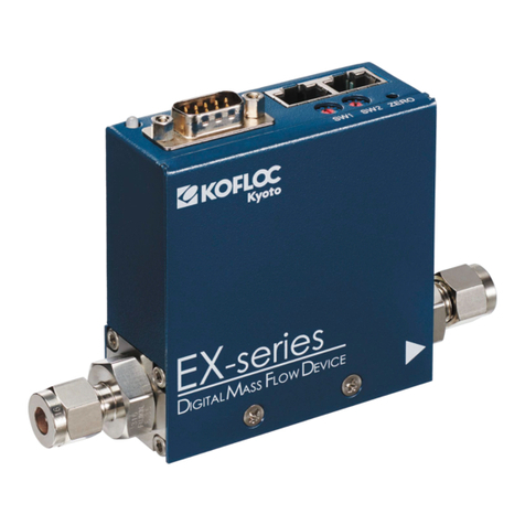
Kofloc HFM-301 Series User manual
Kofloc
Kofloc EX-250S User manual

Kofloc
Kofloc FM01 Series User manual

Kofloc
Kofloc EX-550 User manual

Kofloc
Kofloc FM31 Series User manual
Kofloc
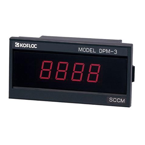
Kofloc DPM-3 User manual
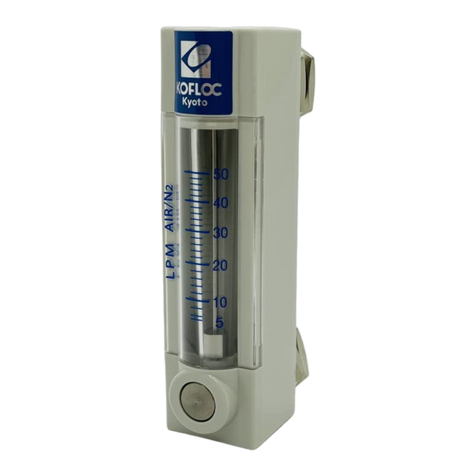
Kofloc
Kofloc RK20T Series User manual

Kofloc
Kofloc RK1975 Series User manual

Kofloc
Kofloc FML-500 User manual

Kofloc
Kofloc 8700 Series User manual

Kofloc
Kofloc HFM-200 Series User manual
Popular Measuring Instrument manuals by other brands

Powerfix Profi
Powerfix Profi 278296 Operation and safety notes

Test Equipment Depot
Test Equipment Depot GVT-427B user manual

Fieldpiece
Fieldpiece ACH Operator's manual

FLYSURFER
FLYSURFER VIRON3 user manual

GMW
GMW TG uni 1 operating manual

Downeaster
Downeaster Wind & Weather Medallion Series instruction manual

Hanna Instruments
Hanna Instruments HI96725C instruction manual

Nokeval
Nokeval KMR260 quick guide

HOKUYO AUTOMATIC
HOKUYO AUTOMATIC UBG-05LN instruction manual

Fluke
Fluke 96000 Series Operator's manual

Test Products International
Test Products International SP565 user manual

General Sleep
General Sleep Zmachine Insight+ DT-200 Service manual


