Kofloc 3810S User manual

MJ400022K1
THERMAL MASS FLOW SENSOR
MODEL3810S
INSTRUCTION MANUAL

MJ400022K1
《Prior to Use》and 《Precautions for Safe Use》
Various visual signs are contained in this manual and attached to the product
to ensure correct handling of the product and to prevent possible personal
injury and property damage. Their meanings are as follows.
Ignoring this sign and handling the product
incorrectly will immediately result in death or serious
injury.
Ignoring this sign and handling the product
incorrectly may result in death or serious injury.
Ignoring this sign and handling the product
incorrectly may result in personal injury or damage
to property.
・The manual is subject to change without notice for improvement.
・The product and this manual have been carefully prepared, but if you notice any insufficiency,
mistakes or omissions, please inform us.
・KOFLOC shall not be liable whatsoever for damages to or failures of the equipment which
may result from neglecting the precautions contained in this manual or using the equipment in
a manner not authorized by this manual
CAUTION
WARNING
DANGER
!
!
!

MJ400022K1
Table of Contents
1. Precautions for Handling
1-1 Checking the ID Plate
1-2 Precautions for Transportation
1-3 Precautions for Product Storage
2. Overview
2-1 Principle of Operation
2-2 Standard Specifications
2-3 External Dimensions
3. Configuration
3-1 Configuration of the Thermal Mass Flow Meter
3-2 Precautions
4. Installation
4-1 Installation Site
4-2 Contamination of the Piping System
4-3 Installation Posture
4-4 Installation Method
4-5 Wiring
5. Operation
5-1 Warming Up
5-2 Zero/Span Calibration
5-3 Run
5-4 Precautions for Use
5-5 Gases Not Listed in Specifications (Conversion Factor)
6. Troubleshooting
6-1 No Output
6-2 Unstable Flow Rate Indication
6-3 Significantly Different Flow Rate Indication
6-4 Significantly Different Zero
7. Maintenance
7-1 Zero/Span Calibration
7-2 Cleaning the Inlet and Outlet Joints
8. Product warranty

MJ400022K1
1. Precautions for Handling
【1-1 Checking the ID Plate】
The ordered products have been assembled and adjusted one by one according to the specifications.
The ID plate attached to the back of the case shows the gases to use, flow rate and other specifications.
Check to see if they comply with your order specifications.
Check items
①Model
②Flow rate
SCCM = ml/min at 0℃:1 atm (101.3 KPa)
SLM = l/min at 0℃:1 atm (101.3 KPa)
NCCM = ml/min at 0℃:1 atm (101.3 KPa)
NLM = l/min at 0℃:1 atm (101.3 KPa)
The unit of the flow rate is basically based on 0℃and 1 atm. To satisfy the request for the unit
to be based on 20℃and 1 atm, the calibration temperature and atmospheric pressure will be
added to the flow rate unit.
Example: SLM( 0℃, 1 atm)・・・・・・Reference state at 0℃and 1 atm.
SLM(20℃, 1 atm)・・・・・Reference state at 20℃and 1 atm.
③Fluid name
④Marking of the serial No.
【1-2 Precautions for Transportation】
To prevent damage during transportation, it is requested that the product be moved to the installation
site in the style as it has been received from KOFLOC.
【1-3 Precautions for Product Storage】
If the product will not be put in operation for a long period of time after it arrived at your site, failures may
develop for unexpected reason.
If it is known that the product will not be used for a long period of time, take the following precautions:
1) Keep the product in the packing in which the product was received.
2) Select a place to store the product that satisfies the following requirements:
①A place protected against rain and water.
②A place free of vibration and impact.
③A place where the product can be kept at normal temperature and humidity (about 25℃
and 65%).
④A place free of dust.
⑤A place free of corrosive gases.
⑥A place free of strong electric or magnetic field.
3) To store the product that has been used, purge it with clean air or N2to ensure that the
measuring gas will not remain in the flow meter.
Protect the inlet and outlet of the measuring gas with caps to prevent intrusion of dust.

MJ400022K1
2. Overview
This flow meter converts flow rates of gases to electric signals and enables measurement of flow rates at
very low cost.
It replaces the conventional float type flow meter and ensures highly accurate flow rate measurement.
【2-1 Principle of Operation】
The flow detect sensor is wound by heating wires on the outside of the metallic capillary in two
places. When gas flows to this capillary, the heat of the heating wire in the upstream is removed by
the gas and its temperature drops. The heat in the upstream is conducted to the downstream to
cause a difference in the resistance values of these heating wires.
The difference in temperature in these two places is proportional to the flow rate of the gas. This
temperature difference is used to calculate a flow rate, which is converted to an electric signal.
When a bypass capillary to bypass the flow to the sensor pipe is incorporated, the gas flow to the
sensor is restricted to enable the equipment to be used for a wide range of flow rates.
The detected flow rates are output as electric signals from 0 to 5 VDC.
Note 1: Do not use the product in such a way as to take measurements at a flow rate above the full scale
or perform control using such measured values. Aflow of an excessive amount of gas may
cause saturation and reversal of the output values to disable accurate flow rate measurement.
*About saturation and reversal: If an amount of gas exceeding the full scale flows to the MFS,
the given heat quantity of the sensor heater will be exceeded at a certain point of the flow rate
due to the characteristics of the thermal sensor, which will cause the saturation and then
reversal phenomena.
Saturation point
5
15
Full-scale flow rate
Flow rate
0
Output
voltage (V)
Output
upper limit
Reversal

MJ400022K1
【2-2 Standard Specifications】
Model
Item
3810S
Flow rate range
N2converted (F.S.) ※1
10 ml/min –2 l/min
3 l/min –50 l/min
Gases to measure
Air, N2, O2, He,Ar, CO2, H2
Accuracy
±3%F.S. max
±5%F.S. max
Reproducibility
±0.5%F.S. max
Pressure resistance
980kPa ※2
Working ambient
temperature
5 –45℃
(Performance guaranteed at 15℃–35℃0.2%F.S./℃)
Workingambienthumidity
10 –85%R.H. (No condensation)
Drive power supply
±15 VDC±5% 60mA
Flow rate output signal
0 –5 VDC
Connection
Rc 1/4
Material in contact with gas
SUS303, Teflon, Viton
Weight
Approx. 250 g
Approx. 350 g
<Note> (※1) F.S. :Full-scale flow rate
(※2) 98.07 KPa = 1Kg/cm2G
【2-3 External Dimensions】
See the following pages.

MJ400022K1

MJ400022K1

MJ400022K1
3. Configuration
【3-1 Configuration of the Thermal Mass Flow Meter】
Required power supply to operate the mass flow meter (Model 3810S):
DC constant voltage power supply: ±15 VDC±2%, +40 mA/-10 mA(Model 3810S)
1) Peripheral equipment of the mass flow meter (Model 3810S)
①DC power supply: PSK-2TFX, 85 –132 VAC (50/60 Hz), 0.4 A (0.6 A)
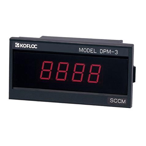
②Flow rate indicator DPM-3 +5 VDC±5% 120 mA
ALM-4 +5 VDC±5% 60 mA
ACM-10 +5 VDC±5% 60 mA
Flowrateindicator+DCpowersupply CR-700 100VAC±10%(50/60Hz),18 VA
③One set of special connecting cables (If a cable longer than 1 m is required, please contact KOFLOC.)
2) Electric wiring diagram of the mass flow meter (Model 3810S)
Example:A combination of Model 3810S and PSK-2TFX and DPM-3
Flow rate output
signal
Flow rate output signal
COM
Power +15 VDC
Power –15 VDC
Power COM
1. ○
2. ○
3. ○
4. ○
5. ○
Flow rate output signal
FlowrateoutputsignalCOM
(Power +15 VDC)
(Power –15 VDC)
Indicator drive power
+5VDC
Indicator drive power 0
VDC
1. ○
2. ○
3. ○
4. ○
5. ○
6. ○
Power PSK-2TFX
Power +15 VDC
Power COM
Power –15 VDC
Flowrateoutputsignal
Flow rate output signal COM
1. ○
2. ○
3. ○
4. ○
5. ○
Model
3810S
Flow rate output signal
FlowrateoutputsignalCOM
(Flowrateoutputsignal)
(FlowrateoutputsignalCOM)
Indicatordrivepower+5VDC
Indicatordrivepower0VDC
1. ○
2. ○
3. ○
4. ○
5. ○
6. ○
DPM-3(Indicator)

MJ400022K1
【3-2 Precautions】
1) Use clean and dry gas with the mass flow meter. The dryness condition must be a dew point
below –20℃at atmospheric pressure.
2) A 100-micron filter is installed at the gas inlet. However, if the meter is to be used in a line where
dust and mist might be produced, install a filter of about 10-micron in front of the meter to remove
them.
4. Installation
Install the meter in a place that is free of dust, dirt and water and take measures to prevent
insulation failure due to condensation. If the temperature of the installation site is likely to rise
due to equipment around the meter, provide necessary precautions such as installing a cooling
fan to ensure good ventilation. Do not install the meter in a place that is subjected to vibration
constantly, because vibration may cause a contact failure of cable connections.
・Never install the meter in a damp or humid place. Hazard of
electric shock.
・Do not install the meter in a place where the ambient
temperature may rise excessively. Such a place will cause
the temperature of the internal circuit to rise and damage it.
・The installation of the meter in a place that is subjected to vibration
constantly may cause a contact failure of cable connections.
【4-1 Installation Site】
1) The mass flow meter is designed for indoor use.
Never install the meter in a place where it may be wetted. The meter may fail.
Install the meter in a place that is well ventilated and has little change in humidity.
2) Install the meter in a place free of vibration and impact.
3) Do not install the meter in a place that is under direct sunlight or very hot or humid.
4) Install the meter in a place free of dust.
5) Install the meter in a place free of corrosive gases.
6) Install the meter in a place free of strong electric or magnetic field.
7) Be sure to conduct leak tests of the piping after installation.
8) Be sure to install the meter horizontally.
9) Always use the special connecting cables.
(The use of a cable longer than 1 m may disable accurate measurement of the flow rate due to a
voltage drop.)
Note that the use of the meter out of the specifications is a cause of failure.
CAUTION
!

MJ400022K1
【4-2 Contamination of the Piping System】
Be sure to use well-cleaned pipes and joints for piping. Astandard filter has been installed. However,
if a large amount of dust adheres, the gas flow will be disturbed. In particular, if air from a compressor
or blower fan is used, it is likely that a large amount of oil mist and water may enter the meter. In such
a case, always install an oil filter or water removing filter in front of the meter.
【4-3 Installation Posture】
Install the meter horizontally.
Lay piping so that the gas inlet and outlet are positioned as indicated on the ID plate.
【4-4 Installation Method】
1) For installation, utilize the mounting threaded holes (M3) on the bottom of the meter block.
2) The standard piping connection is Rc 1/4. Use suitable joints and be sure that they will not leak.
【4-5 Wiring】
For a detailed description of wiring, refer to 3. Configuration.
Be sure to use special connecting cables.
Be sure to insert the connectors firmly to the designated places.
5. Operation
【5-1 Warming Up】
After the power was turned on, warm up the meter for 15 minutes or longer with the supply of gas
stopped.
If the meter is not warmed up, the measuring accuracy will deteriorate.
【5-2 Zero/Span Calibration】
If the user has the reference flow meter, the span may be calibrated. If no reference meter is available,
conduct the zero calibration only.
1) Zero calibration
When the indication has become stable with gas shut off after the meter was warmed up, using a
small screwdriver, adjust the “ZERO”variable resistor installed on the top of the case to zero. Be
sure that the indicated value or the output becomes zero.
2) Span calibration
If the reference meter is not available, never tinker with the “SPAN”variable resistor. Connect the
reference flow meter to the gas outlet.
With Model 3810S, adjust the “SPAN”variable resistor so that when gas is let flow at the full-scale
rate, the flow rate signal output becomes 5 VDC.
If the user does not have the reference flow meter, never tinker with the “SPAN”variable resistor.

MJ400022K1
【5-3 Run】
Model 3810S has been set ready for measurement. It outputs flow rate signals from 0 to 5 VDC for
flow rates from zero to the full scale.
Example: Full scale 1 l/min: Flow indication on PM-3 is 1.000 l/min
Full scale 10 l/min: Flow indication on PM-3 is 10.00 l/min
Full scale
2 l/min: Flow indication on PM-3 is 2.00 l/min
Full scale 20 l/min: Flow indication on PM-3 is 20.0 l/min
【5-4 Precautions for Use】
1) Calibration of actual gases
For gases other than air, N2, O2, H2, He, Ar and CO2, actual gas calibration has been conducted.
Other gases are calibrated by use of a conversion factor.
If gases not listed in the specifications are to be used, always test the corrosion resistance of the
areas in contact with gas.
2) Gas stop
Install a stop valve on the gas inlet or outlet.
【5-5 Gases Not Listed in Specifications (Conversion Factor)】
If the thermal mass flow meter that has been calibrated with one type of gas is used for other gas, the
indicated value does not match the actual flow rate.
For example, if He is let flow to the meter that has been calibrated with N2, the actual flow rate is 1.43
times the indicated flow rate.
For detailed data of the conversion factors, please contact KOFLOC.

MJ400022K1
6. Troubleshooting
If the meter is considered to have failed, in order to prevent short circuit accidents, never use the
connector pins of the meter to check output voltages, but be sure to use such safe places as the
check terminals of the connected equipment.
If the meter failed, please contact KOFLOC.
DANGER
Never disassemble the meter. Touching the inside
of the meter may cause electric shock.
【6-1 No Output】
1
No power
Check the output of the DC power supply.
2
Connector connection
failure
Check to see if the connectors are fitted correctly.
3
Cable breakage
Check the continuity with a tester.
4
No gas flow
Check the gas source pressure and gas flow.
5
Clogged piping
Check the solenoid valve, etc. after the outlet.
6
Clogged sensor pipe
Please contact KOFLOC.
7
Sensor amp. failure
Please contact KOFLOC.
8
Indication meter failure
Replace the meter.
【6-2 Unstable Flow Rate Indication】
1
Source pressure valve
faulty
Check the supply adjust valve.
2
Constant flow valve
faulty
Check the valve.
3
Sensor amp. failure
Please contact KOFLOC.
4
Power supply faulty
Replace the DC power supply.
【6-3 Significantly Different Flow Rate Indication】
1
Span calibration
error
Calibrate the span with the reference flow meter.
2
Gas leak
Piping ・・・・・・・・・・・・・・・・・ Stop the leak.
Sensor, valve ・・・・・・・・・・ Contact KOFLOC.
!

MJ400022K1
【6-4 Significantly Different Zero】
1
Incorrect power supply
voltage
Replace the power supply.
2
Sensor faulty
Please contact KOFLOC.
7. Maintenance
【7-1 Zero/Span Calibration】
If the user can use the reference flow meter, calibrate both the zero and span. If not, calibrate the zero
only.
【7-2 Cleaning the Inlet and Outlet Joints】
Clean the inlet and outlet joints. They should be removed in a clean place where dust will not enter
the block. During maintenance, never disassemble the sensor.
If it is disassembled, the initial performance cannot be guaranteed.
8. Product warranty
1. The contents of warranty
①Warranty period
The warrant period shall be one year after the shipment.
②Warranty range
If a malfunction of the product you purchased occurs because of our responsible reasons, offer of
substitute or it will be charge-free repaired in our factory. But if a malfunction of the machine occurs
due to the following reasons, even within the warrant period, it becomes the outside for a warranty.
(a) Malfunctions due to erroneous applications, repairs or remodeling.
(Including the case in which the manufacturing specification differs from the application conditions.)
(b) Malfunctions due to the falling after the purchase.
(c) Malfunctions caused by natural disasters such as fire, earthquake, water disaster and lightning stoke,
or riots or wars.
(d) Malfunctions caused by mixing-in of foreign matters out of the piping.
(e) Malfunctions caused by the peculiar problems due to combinations with other built in equipment.
In addition, a warranty here means the warranty of the product simple substance of our company. So
the damage induced by failure of the products of our company shall be eliminated from the object of
warranty.

MJ400022K1
URL:http://www.kofloc.co.jp
Table of contents
Other Kofloc Measuring Instrument manuals

Kofloc
Kofloc FML-500 User manual

Kofloc
Kofloc DPM-3 User manual

Kofloc
Kofloc RK20T Series User manual

Kofloc
Kofloc EX-550 User manual

Kofloc
Kofloc FM01 Series User manual

Kofloc
Kofloc 8700 Series User manual

Kofloc
Kofloc 3810DSII User manual

Kofloc
Kofloc HFM-200 Series User manual

Kofloc
Kofloc EX-700R User manual

Kofloc
Kofloc EX-700R User manual

Kofloc
Kofloc EX-250S User manual

Kofloc
Kofloc FM31 Series User manual

Kofloc
Kofloc 3100 User manual

Kofloc
Kofloc RK1812 Series User manual

Kofloc
Kofloc FML300-D Series User manual

Kofloc
Kofloc HFM-301 Series User manual

Kofloc
Kofloc 8700 Series User manual

Kofloc
Kofloc RK1975 Series User manual

Kofloc
Kofloc 3760 Series User manual