manuals.online logo
Brands
  1. Home
  2. •
  3. Brands
  4. •
  5. Kohler
  6. •
  7. Plumbing Product
  8. •
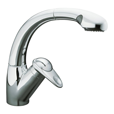
  9. Kohler K-72218 Operation manual

Kohler K-72218 Operation manual

P A R I S
11186051-D2-A
Installation & User Guide / Guide d’installation & d’utilisation / Installations- und
Benutzungsanleitungen / Установка и инструкция по пользованию
FR
DRU
GB Sensate Electronic Kitchen Tap
K-72218, E72218
Сенсорный электронный
кухонный смеситель
Elektrische Sensor-Küchenbraus
Robinet de cuisine électronique
Sensate
P A R I S
2
1186051-W2-B
GB
FR
Important Instructions / Instructions importantes / Wichtige Hinweise / Важные примечания
Rags3/8" Pliers Adjustable Wrenches
3/8"
Phillips Screwdriver
Bucket
Pliers Adjustable Wrenches
3/8"
Phillips Screwdriver
Bucket
Pliers Adjustable Wrenches
Rags3/8" Pliers Adjustable Wrenches
•Installation must be carried out in accordance with these instructions, and must be conducted
•The plumbing installation must comply with the requirements of UK Water regulations/Bye-
company or water undertakers.
•This appliance must be earthed. Ensure supplementary bonding complies with the
“Requirements for Electrical Installations”. The appliance is intended to be permanently
•Mains connections are exposed when the cover is removed.
•Disconnect power and shut off the water supply before servicing.
•The tap spout contains a magnet. Do not allow items susceptible to electromagnetic damage
to come into close proximity to the spout.
•Flush all pipework prior to installing the tap.
•The water supplies to this product must be isolated if the product is not to be used for a long
period of time. If the product or pipework is at the risk of freezing during this period they
should also be drained of water.
•For new installations, assemble the tap to the sink before installing the sink.
•For uneven mounting surfaces (such as tile grout line) apply a suitable sealant under the tap.
•L’installation doit être effectuée conformément à ces instructions et doit être faite par du
•L’installation de plomberie doit être conforme aux exigences des compagnies de distribution
••Cet appareil doit être mis à la terre. Assurez une liaison supplémentaire, conformément aux
normes électriques. L’appareil est destiné à être connecté en permanence avec l’installation
•Les connexions réseau sont exposées lorsque le couvercle est enlevé.
•Débranchez l’alimentation électrique et coupez l’arrivée d’eau avant d’intervenir.
•Le bec du robinet est aimanté. N’utilisez pas d’objets susceptibles de subir des dommages
électromagnétiques à proximité immédiate du bec.
•Rincez toute la tuyauterie avant d’installer le robinet.
•Les conduites d’eau de ce produit doivent être isolées si le produit n’est pas utilisé durant
une longue période. Si le produit ou la tuyauterie sont susceptibles d’être exposés au gel
durant cette période, ils doivent être purgés auparavant.
•Pour les nouvelles installations, montez le robinet sur l’évier avant d’installer celui-ci.
•Pour des surfaces de montage inégales comme des joints de carrelage ) appliquez un produit
d’étanchéité approprié sous le robinet .
P A R I S
31186051-W2-B
D
RU
•Die Installation muss nach den hier vorliegenden Hinweisen erfolgen, und durch bestimmtes,
•Die Wasserinstallation muss den Anforderungen der Trinkwasserverordnung/Bestimmungen
des Vereinted Königreiches (Schottland) oder bestimmten anderen Vorschriften und
Praktiken entsprechen, die von der lokalen Wasserversorgung oder von Wasserunternehmen
vorgegeben sind.
•Dieses Gerät muss geerdet sein. Vergewissern Sie sich, dass die zusätzlichen Anschlüsse
die “Anforderungen an Elektroinstallationen” erfüllen. Das Gerät ist für eine dauerhafte
Verbindung zur bestehenden Verkabelung des Leitungsnetzes vorgesehen. Eine elektrische
Isolierung des Gerätes sollte an der bestehenden Verkabelung gemäß den lokalen
Kabelvorschriften angebracht werden.
•Die Wasseranschlüsse liegen offen, sobald die Verdeckung entfernt wird.
•Stromversorgung abschalten und die Wasserzufuhr abdrehen, bevor Sie das Gerät warten.
•Die Wasserhahntülle enthält einen Magneten. Bringen Sie keine Objekte, die
elektromagnetische Schäden verursachen könnten in die Nähe der Tülle.
•Spülen Sie alle Leitungen vor der Installation der Brause durch.
•Die Wasserzuläufe zu diesem Produkt mussen isoliert sein, falls das Produkt über einen
längeren Zeitraum nicht verwendet wird. Falls das Produkt oder die Leitung innerhalb des
besagten Zeitraumes einfrieren könnten, sollten sie auch entleert werden.
•Bringen Sie bei neuen Installationen zuerst die Brause an das Waschbecken an und
montieren Sie dann das Waschbecken.
•unter der Brause auf.
•Установка смесителя должна осуществлятьсявсоответствии снастоящими
инструкциями уполномоченным, квалифицированным и компетентным персоналом.
•Инженерное оборудование помещения должно соответствовать нормативам и
правилам вотношении водоснабжения, принятым на территории Соединенного
Королевства (для Шотландии), или любым специфическим нормативам иправилам,
установленным местной компанией по водоснабжениюлибо водоснабжающими
предприятиями.
•Настоящее изделие должно быть заземлено. Обеспечьте соответствие дополнительного
заземления изделия «Требованиям кэлектрооборудованию». Изделиепредназначено
для постоянного подключения кстационарной сети электропитания. Электрическая
изоляция изделия должна быть обеспечена путем жесткой разводки всоответствии с
местными нормативами в отношении электропроводки.
•При снятой крышке открываются сетевые соединения.
•Перед обслуживанием отключите питание и закройте воду.
•Вносике смесителя установлен магнит. Не подносите близко кносику смесителя
предметы, которые могут быть повреждены магнитным полем.
•Перед установкой смесителя промойте все трубы.
•Если изделие не будет эксплуатироваться втечение долгого времени, отключите
подачу кнему воды. Если вэтот период существует риск замерзания изделия или
труб, слейте из них воду.
•При новой установке сначала установите смеситель на раковину, азатем установите
раковину.
•При установке на неровные поверхности (например, на шов заливки раствора под
плитку) нанесите под смеситель соответствующий герметик.
P A R I S
4
1186051-W2-B
1
2
34
6 mm
P A R I S
51186051-W2-B
5 6
7 8
76 mm min
1 min
мин. 76 мм
P A R I S
6
1186051-W2-B
9
10 11
P A R I S
71186051-W2-B
12
Caution! The outlet hose must not be taut or kinked when installed. Locate the solenoid
valve within 178 mm to 203 mm from the tap.
Note!
13
Cover
Tab
Bracket
GB
FR
D
RU
Attache
Lasche
Лапка
Couvercle
Verdeckung
Крышка
Bracket
Support
Halter
Кронштейн
Attention ! Le tuyau d’évacuation ne doit pas être trop tendu ni plié lors de l’installation.
Placez l’électrovanne à une distance de 178 à 203 mm du robinet.
Note ! .
Achtung! Der Ablaufschlauch darf bei der Installation nicht zu straff oder geknickt sein.
Bringen Sie das Solenoidventil in einem Abstand von 178 mm und 203 mm zur Brause an.
Wichtiger Hinweis! Verwenden Sie passende Fixierungen, um den Halter an der Wand
anzubringen.
Внимание! Не допускайте излишнего натяжения или перекручивания гибкого
напорного шланга во время установки. Расположите электромагнитный клапан на
расстоянии 178–203 мм от смесителя.
Примечание. Используйте соответствующий крепеж для установки кронштейна на
стену.
P A R I S
8
1186051-W2-B
14
15 16
Handle Switch
Power Cord
Apply Grease (Provided)
Appliquez la graisse (fournie)
Einfetten (mitgeliefert)
Нанесите смазку (входит в комплект поставки)
Solenoid Wire
Fil de l'électrovanne
Solenoidkabel
Провод электромагнита
P A R I S
91186051-W2-B
17 18
LED
19 20
51-76 mm
P A R I S
10
1186051-W2-B
21
22
P A R I S
11 1186051-W2-B
23
GB
tie below the weight and the clamp
For UK Installations Only
25 mm
Weight
Clamp
Cable Tie
Overspill
Level
P A R I S
12
1186051-W2-B
OFF
1
2
34
P A R I S
13 1186051-W2-B
GB LED Indication
Handle LED Illuminates when the sensor is active
Circuit Board LED Indicates there is power to the circuit board
Note! The sensor LED’s are only visible inside the spout when the spray hose is extended.
Green Sensor LED Indicates there is power to the sensor
Yellow Sensor LED Illuminates when an object has been detected by the sensor
Features
Automatic Shut-off After four minutes of inactivity, the water will autimatically shut OFF
Sensor override In the event of a power loss, the sensor function can be bypassed
by turning in the override feature on the solenoid valve. The tap can
then be operated manually
Indication LED
Poignée LED S’allume lorsque le capteur est actif
Carte du circuit LED Indique si la carte du circuit est alimentée en courant
Note! Les capteurs LED ne sont visibles dans le bec que lorsque le tuyau de la douche est
étiré.
Capteur LED vert Indique que le capteur est sous tension
Capteur LED jaune S’allume lorsqu’un objet est détecté par le capteur
Marques
Arrêt automatique Après quatre minutes d’inactivité, l’eau est automatiquement
coupée
Sélecteur du capteur En cas de coupure de courant, la fonction capteur peut être
contournée en tournant le sélecteur de l’électrovanne. Le robinet
peut alors être actionné manuellement
LED-Anzeige
LED-Griff Leuchtet auf, sobald der Sensor aktiv ist
LED-Gehäuse Zeigt den Strom zum Gehäuse an
Wichtiger Hinweis! Die LED-Sensoren sind nur in der Tülle sichtbar, wenn der
Brauseschlauch verlängert wird.
Grüner LED-Sensor
Gelber LED-Sensor Leuchtet auf, sobald ein Gegenstand vom Sensor erfasst wird
Funktionen
automatisches
Abstellen
Nach einigen Minuten ohne Aktivität wird das Wasser automatisch
AUSgeschaltet
Sensorübersteu-
erung
Bei Stromausfall kann die Sensorfunktion umgangen werden,
indem die Umsteuerungsfunktion des Solenoidventils eingeschaltet
wird. Die Brause kann daraufhin manuell betätigt werden
FR
D
P A R I S
14
1186051-W2-B
Manual Override
Sensor
Handle LED
Open Position
Sensor LEDs
RU Индикация СИД
СИД на рукоятке Горит при активном датчике.
СИД на блоке
управления
Указывает на подачу питания на блок управления.
Примечание. СИДы датчика можно увидеть только внутри носика смесителя при
вытягивании шланга разбрызгивателя.
Зеленый СИД
датчика
Указывает на подачу питания к датчику.
Желтый СИД
датчика
Загорается при определении датчиком предмета.
Особенности
Автоматическое
отключение
Подача воды будет автоматически отключена через четыре
минуты бездействия.
Блокировка
датчика
При сбое электропитания датчик можно обойти за счет функции
блокировки на электромагнитном клапане. После блокировки
смесителем можно пользоваться вручную.
Manual Override
Sélecteur manuel
Manuelle Umsteuerung
Блокировка автоматики
Sensor
Capteur
Sensor
Датчик
Handle LED
Poignée LED
LED-Griff
СИД на рукоятке
Open Position
Position ouverte
Öffnungsstellung
Положение «Открыто»
Sensor LEDs
Capteur LED
LED-Sensoren
СИДы датчика
P A R I S
15 1186051-W2-B
Tap Troubleshooting Guide
Symptons Probable Causes Recommended Action
No Water Flow The shut off valves are closed
Handle is in the closed position
The hot and/or cold supply hose is
kinked
The outlet hose is kinked
Handle LED is not lit
Sensor LED is not lit
One or more screens are blocked
Make sure the shut off valves are open
Rotate the handle to the open position
kinked
located within 178 mm to 203 mm from
the tap base
Refer to ‘Handle Switch
Troubleshooting Table’
Refer to ‘Sensor Troubleshooting Table’
Refer to ‘Cleaning the Screens’
Low Water Flow The shut off valves are partially closed
Handle is partially closed
The hot and/or cold supply hose is
kinked or twisted
The outlet hose is kinked
One or more screens are blocked
Cracked diaphragm
Make sure that the shut off valves are
fully open
Rotate the handle to the fully open
position
kinked or twisted
located within 178 mm to 203 mm from
the tap base
Refer to ‘Cleaning the Screens’
Replace the solenoid valve assembly
Poor Spray
Pattern
The spray nozzles are blocked
dislodge any debris
Circuit board
LED is not lit
No power to curcuit board
Power cord is plugged into a switched
outlet
Check the power supply connections to
the circuit board
Plug the power cord into an unswitched
board LED lights
Troubleshooting / Dépannage / Fehlerbehebung / Поиск и устранение неисправностей
GB
P A R I S
16
1186051-W2-B
Handle Switch Troubleshooting Guide
Symptons Probable Causes Recommended Action
Handle LED is
lit when handle
is closed
Valve setscrew needs adjustment Refer to the ‘Handle LED Adjustment’
section
Handle does
not return to the
upright position
Valve setscrew needs adjustment Refer to the ‘Handle LED Adjustment’
section
Water does not
fully shut off
Valve setscrew needs adjustment Refer to the ‘Handle LED Adjustment’
section
Handle LED
does not
illuminate
when handle is
rotated open
Loose handle switch wire connection
Circuit board is not working
Check handle switch wore connection
to the circuit board
Replace the cover assembly
Sensor Troubleshooting Guide
Symptons Probable Causes Recommended Action
Intermittent
sensor
operation
Debris on the sensor lens
Sensor is detecting steam
Use mild soap and water to remove the
debis from the sensor lens
Rotate the spout away from the steam
Handle LED is
lit, but green
sensor LED is
not
Loose sensor wire connection
Debris on the sensor wire connector
Circuit board is not working
Check sensor wire connection to the
curcuit board
At the circuit board, gently disconnect,
clean, and reconnect the sensor wire
connector
Replace the cover assembly
Yellow sensor
LED does not
illuminate with
an object in
front of it
Object is clear or colour is
undetectable by the sensor
Debris on the wire sensor connector
Test the sensor wire using your hand
At the circuit board, gently disconnect,
clean, and reconnect the sensor wire
connector
P A R I S
17 1186051-W2-B
Solenoid Troubleshooting Guide
Symptons Probable Causes Recommended Action
Water leaking
from the valve
Hose connections not secure
Internal leak
Turn off the main power and water
supply. Check all the connections
Replace the solenoid valve assembly
No audible
‘Click’ when
solenoid is
activated
Loose solenoid wire connection
Solenoid valve is not functioning
Check solenoid wire connection to the
circuit board
Replace the solenoid valve assembly
Guide de dépannage du robinet
Symptômes Causes probables Action recommandée
Pas de débit
d’eau
Les vannes d’arrêt sont fermées
La poignée est en position fermée
Le tuyau d’alimentation d’eau chaude
et/ou d’eau froide est plié
Le tuyau de vidange est plié
La poignée LED n’est pas allumée
Le capteur LED n’est pas allumé
Un ou plusieurs écrans sont bloqués
Assurez-vous que les vannes d’arrêt
soient ouvertes
Tournez le bouton en position ouverte
Assurez-vous que les tuyaux
d’alimentation ne sont pas pliés
Assurez-vous que l’électrovanne soit
située entre 178 et 203 mm de la base
du robinet
Veuillez vous reporter au “Tableau de
dépannage de l’interrupteur”
Veuillez vous reporter au “Tableau de
dépannage du capteur”
Veuillez vous reporter au “Nettoyage
des écrans”
Mauvais modèle
de douche
Le diffuseur de la douche est bouché
d’y ôter d’éventuels débris
La carte du
circuit LED n’est
pas allumée
Pas d’alimentation sur la carte du
circuit
Le cordon d’alimentation est branché
sur une commutation de sortie
l’alimentation à la carte du circuit
Branchez le cordon d’alimentation sur
une ligne non commutée
100 - 240 V AC. Assurez-vous que la
carte du circuit LED s’allume
FR
P A R I S
18
1186051-W2-B
Faible débit
d’eau
Les vannes d’arrêt sont partiellement
fermées
La poignée est partiellement fermée
Le tuyau d’alimentation d’eau chaude
et/ou d’eau froide est plié ou tordu
Le tuyau de vidange est plié
Un ou plusieurs écrans sont bloqués
Assurez-vous que les vannes d’arrêt
sont complètement ouvertes
Tournez la poignée en position com-
plètement ouverte
Assurez-vous que les tuyaux
d’alimentation ne sont pas pliés ou
tordus
Assurez-vous que l’électrovanne soit
située entre 178 et 203 mm de la base
du robinet
Veuillez vous reporter au “Nettoyage
des écrans”
replacez l’ensemble de l’électrovanne
Guide de dépannage de l’interrupteur
Symptômes Causes probables Action recommandée
La poignée LED
est allumée lor-
sque la poignée
est fermée
La vis de réglage de la vanne doit être
ajustée
Veuillez vous reporter au chapitre
“Réglage de la poignée LED”
La poignée ne
revient pas en
position verti-
cale
La vis de réglage de la vanne doit être
ajustée
Veuillez vous reporter au chapitre
“Réglage de la poignée LED”
L’eau ne
s’arrête pas
complètement
La vis de réglage de la vanne doit être
ajustée
Veuillez vous reporter au chapitre
“Réglage de la poignée LED”
La poignée LED
ne s’allume
pas lorsque la
poignée est
en position
d’ouverture
l’interrupteur de la poignée
La carte du circuit ne fonctionne pas
-
l’interrupteur sur la carte du circuit
Replacez l’ensemble du couvercle
P A R I S
19 1186051-W2-B
Guide de dépannage de l’électrovanne
Symptômes Causes probables Action recommandée
Fonctionnement
intermittent du
capteur
Débris sur la lentille du capteur
Le capteur détecte de la vapeur
Utilisez de l’eau et un détergent doux
pour enlever les débris de la lentille du
capteur
Tournez le bec à l’abri de la vapeur
La poignée LED
est allumée,
mais le capteur
LED vert ne l’est
pas
capteur
capteur
La carte du circuit ne fonctionne pas
capteur sur la carte du circuit
Sur la carte du circuit, déconnectez
doucement, nettoyez et reconnectez le
Replacez l’ensemble du couvercle
Le capteur
LED jaune ne
s’allume pas
lorsqu’un objet
est placé devant
lui
L’objet est transparent ou la couleur
n’est pas détectable par le capteur
capteur
main
Sur la carte du circuit, déconnectez
doucement, nettoyez et reconnectez le
Guide de dépannage du capteur
Symptômes Causes probables Action recommandée
Fuite d’eau de
la vanne
Raccords de tuyaux non sécurisés
Fuite interne
Débranchez l’alimentation électrique et
l’eau. Contrôlez tous les raccords.
replacez l’ensemble de l’électrovanne
Pas de “clic”
audible lorsque
l’électrovanne
est activée
l’électrovanne
L’électrovanne ne fonctionne pas
l’électrovanne à la carte du circuit
replacez l’ensemble de l’électrovanne
P A R I S
20
1186051-W2-B
Fehlersuchanleitung der Brause
Symptome Mögliche Ursachen Maßnahmen
Kein Wasser- Die Absperrventile sind geschlossen
Griff ist in geschlossener Position
Der Heiß- und/oder Kaltwasserzulauf-
schlauch ist geknickt
Der Ablaufschlauch ist geknickt
LED-Griff leuchtet nicht
LED-Sensor leuchtet nicht
Ein oder mehrere Siebe sind verstopft
Stellen Sie sicher, dass die Absper-
rventile geöffnet sind
Drehen Sie den Griff in die geöffnete
Position
Stellen Sie sicher, dass die Wasserzu-
laufschläuche nicht geknickt sind
Stellen Sie sicher, dass sich das
Solenoidventil in einem Abstand von
178 mm und 203 mm zur Armatur der
Siehe ‘Fehlerbehebung des
Griffschalters’
Siehe ‘Fehlerbehebung des Sensors’
Siehe ‘Reinigung der Siebe’
Geringer Was- Die Absperrventile sind teilweise
geschlossen
Der Griff ist teilweise verschlossen
Der Heiß- und/oder Kaltwasserzulauf-
schlauch ist geknickt oder verdreht
Der Ablaufschlauch ist geknickt
Ein oder mehrere Siebe sind verstopft
Membran durchbrochen
Stellen Sie sicher, dass die Absper-
rventile ganz geöffnet sind
Drehen Sie den Griff, bis dieser voll
geöffnet ist
Stellen Sie sicher, dass die Wasser-
zulaufschläuche nicht geknickt oder
verdreht sind
Stellen Sie sicher, dass sich das
Solenoidventil in einem Abstand von
178 mm und 203 mm zur Armatur der
Siehe ‘Reinigung der Siebe’
Bausatz des Solenoidventils aus-
tauschen
Schlechtes
Sprühmuster
Die Sprühdüsen sind verstopft Reiben Sie Ihren Finger über die
Sprühdüsen, um eventuelle Verun-
reinigungen zu entfernen
D

Other manuals for K-72218

5

This manual suits for next models

1

Other Kohler Plumbing Product manuals

Kohler K1044435 Manual

Kohler

Kohler K1044435 Manual

Kohler WaterTile K-8030 User manual

Kohler

Kohler WaterTile K-8030 User manual

Kohler AIRFOIL 37273T User manual

Kohler

Kohler AIRFOIL 37273T User manual

Kohler Margaux 16228A User manual

Kohler

Kohler Margaux 16228A User manual

Kohler K-10430 User manual

Kohler

Kohler K-10430 User manual

Kohler Kathryn K-2322 Assembly instructions

Kohler

Kohler Kathryn K-2322 Assembly instructions

Kohler K-4774 Assembly instructions

Kohler

Kohler K-4774 Assembly instructions

Kohler K-3524 Assembly instructions

Kohler

Kohler K-3524 Assembly instructions

Kohler K-393 User manual

Kohler

Kohler K-393 User manual

Kohler Cantata K-2199 User manual

Kohler

Kohler Cantata K-2199 User manual

Kohler STANCE K-37467T User manual

Kohler

Kohler STANCE K-37467T User manual

Kohler AMARETTO K-4864T-1/4 User manual

Kohler

Kohler AMARETTO K-4864T-1/4 User manual

Kohler Oblo K-124B16-SANA-CP User manual

Kohler

Kohler Oblo K-124B16-SANA-CP User manual

Kohler 77980T-4 User manual

Kohler

Kohler 77980T-4 User manual

Kohler K-29221T Series User manual

Kohler

Kohler K-29221T Series User manual

Kohler K-1002-H2 Assembly instructions

Kohler

Kohler K-1002-H2 Assembly instructions

Kohler Stance 10317T-4 User manual

Kohler

Kohler Stance 10317T-4 User manual

Kohler TOUCHLESS 32323T-4 User manual

Kohler

Kohler TOUCHLESS 32323T-4 User manual

Kohler K-433 Assembly instructions

Kohler

Kohler K-433 Assembly instructions

Kohler ELLISTON 75522T-4 User manual

Kohler

Kohler ELLISTON 75522T-4 User manual

Kohler 72282T-4 Service manual

Kohler

Kohler 72282T-4 Service manual

Kohler K-10441 User manual

Kohler

Kohler K-10441 User manual

Kohler K-2294 User manual

Kohler

Kohler K-2294 User manual

Kohler Stillness 954T-4 User manual

Kohler

Kohler Stillness 954T-4 User manual

Popular Plumbing Product manuals by other brands

Hans Grohe Metropol Select 110 32571007 Instructions for use/assembly instructions

Hans Grohe

Hans Grohe Metropol Select 110 32571007 Instructions for use/assembly instructions

Hans Grohe Versostat 2 Series Instructions for use

Hans Grohe

Hans Grohe Versostat 2 Series Instructions for use

Hans Grohe Crometta 85 Vario Assembly instructions

Hans Grohe

Hans Grohe Crometta 85 Vario Assembly instructions

Franke FFPD2000 installation guide

Franke

Franke FFPD2000 installation guide

Elkay Vivo LKS6465 Specification sheet

Elkay

Elkay Vivo LKS6465 Specification sheet

Grohe 27 032 manual

Grohe

Grohe 27 032 manual

Sanela SLUN 80P Instructions for use

Sanela

Sanela SLUN 80P Instructions for use

Glacier bay 67236-0001 Use and care guide

Glacier bay

Glacier bay 67236-0001 Use and care guide

Grohe EUROPLUS 20 302 manual

Grohe

Grohe EUROPLUS 20 302 manual

Teka Intra GUB3 quick start guide

Teka

Teka Intra GUB3 quick start guide

Spectrum Brands Pfister Classic F-529-7PF Quick installation guide

Spectrum Brands

Spectrum Brands Pfister Classic F-529-7PF Quick installation guide

Pfister Solo LF029-4SL installation guide

Pfister

Pfister Solo LF029-4SL installation guide

Stern Extreme Series Installation and maintenance guide

Stern

Stern Extreme Series Installation and maintenance guide

Moen 84914 series Specifications

Moen

Moen 84914 series Specifications

Signature Hardware MILAZZO 948577 manual

Signature Hardware

Signature Hardware MILAZZO 948577 manual

Hans Grohe 94148000 Service manual

Hans Grohe

Hans Grohe 94148000 Service manual

Viega Prevista Pure 8569 Instructions for use

Viega

Viega Prevista Pure 8569 Instructions for use

Dallmer CeraLine F installation instructions

Dallmer

Dallmer CeraLine F installation instructions

manuals.online logo
manuals.online logoBrands
  • About & Mission
  • Contact us
  • Privacy Policy
  • Terms and Conditions

Copyright 2025 Manuals.Online. All Rights Reserved.