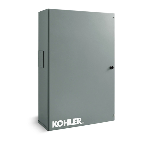
Kohler ZCS series Instruction Manual

AutomaticTransferSwitches
Models:
ZCS
Contactors:
40 to 3000 Amperes
TP-5660 11/98
Operation and
Installation

TP-5660 11/98 Table ofContents
TableofContents
SafetyPrecautions and InstructionsI.........
Introduction i...............................
ListofRelated Materialsi.....................
Service Assistance ii.........................
ServiceInformation ii..........................
Product Indentification ii.......................
Section 1.Specifications 1...................
1.1Purpose 1...................................
1.2Components1...............................
1.3Nameplate 2.................................
1.4PartNumberModelCode 3....................
1.5StandardFeatures4..........................
1.6Ratings4....................................
1.7Application Data 7............................
Section 2.Operation 9.......................
2.1Startup 9....................................
2.2AutomaticOperation 9.........................
2.2.1Failure ofNormalPower10..............
2.2.2Restoration ofNormalPower10..........
2.3ManualOperation 11...........................
2.3.1Programmed Transition Switch,
40--260 Amps12.......................
2.3.2Programmed Transition Switch,
400--3000 Amps13.....................
2.3.3StandardSwitch,800--3000 Amps14......
Section 3.Accessories 15.....................
3.1Programmed Transition 15......................
3.1.1Description 15..........................
3.1.2Adjustment15..........................
3.2OtherAccessories16..........................
Section 4.ScheduledMaintenance 17..........
4.1Inspection and Service 18.......................
4.1.1GeneralInspection 19...................
4.1.2OtherInspectionsand Service 19.........
4.2Testing 19....................................
4.2.1WeeklyGeneratorSetExercise 19........
4.2.2MonthlyAutomaticControlSystem
Test19................................
4.3ServiceSchedule 20...........................
Section 5.Diagrams and Drawings 21..........
Section 6. Installation 55......................
6.1Upon ReceiptofUnit55........................
6.1.1Inspection 55..........................
6.1.2 Lifting 55..............................
6.1.3Unpacking 56..........................
6.1.4Storage 56.............................
6.2MechanicalInstallation 56.......................
6.3Check ManualOperation 56.....................
6.4ElectricalWiring 56............................
6.4.1ACPowerConnections58...............
6.4.2GeneratorStartConnection 59...........
6.4.3Accessoryand ControllerConnections59. .
6.5Preparethe GeneratorSet forOperation 59.......
6.6FunctionalTests60............................
6.6.1Voltage Check 60.......................
6.6.2AutomaticOperation Test61.............
6.7ControllerSetup 61............................
6.8EnsureWarrantyRegistration 61.................
AppendixA.GlossaryofAbbreviationsA-1......

TP-5660 11/98 SafetyPrecautionsand InstructionsI
SafetyPrecautions and Instructions
Atransferswitch,like anyother
electromechanicaldevice,can pose
potentialdangerstolife and limbif
improperlymaintained oroperated.
The bestwayto preventaccidentsisto
be aware ofpotentialdangersand act
safely.Pleaseread and followthe
safetyprecautionsand instructions
belowto preventharmtoyourselfand
others.Thismanualcontains several
typesofsafetyprecautionsand
instructionswhichare explainedbelow.
SAVE THESE INSTRUCTIONS.
DANGER
Dangerindicatesthe presence ofa
hazardthatwill causeseverepersonal
injury,death,orsubstantialproperty
damage.
WARNING
Warning indicatesthe presence ofa
hazardthatcan causeseverepersonal
injury,death,orsubstantialproperty
damage.
CAUTION
Caution indicatesthe presence ofa
hazardthatwill orcan causeminor
personal injuryorpropertydamage.
NOTICE
Noticecommunicatesinstallation,
operation,ormaintenanceinformation
thatisimportantbutnothazardrelated.
Safetydecalsaffixed tothe transfer
switchin prominentplacesadvisethe
operatororservicetechnician of
potentialhazardsandhowtoactsafely.
The decalsarereproduced hereto
improve operator recognition.Replace
missing ordamaged decals.
AccidentalStarting
Accidentalstarting.
Cancause severeinjuryordeath.
Disconnectbattery cablesbefore
working on generatorset. (Remove
negative(--) lead firstwhen
disconnecting battery.Reconnect
negative(--) lead lastwhen
reconnecting battery.)
WARNING
Disabling thegeneratorset.
Accidentalstarting cancause
severeinjuryordeath.Before
working on the generatorsetor
connected equipment, disablethe
generatorsetasfollows:1)Movethe
generatorsetmasterswitchtothe OFF
position.2)Disconnectpowertothe
battery charger.3)Remove battery
cables,negative(--) lead first.
Reconnectnegative(--) lead lastwhen
reconnecting battery.Followthese
precautionsto preventstarting of
generatorsetbyan automatictransfer
switch,remotestart/stop switch,or
engine startcommand fromaremote
computer.
Battery
Sulfuric acidin batteries.
Cancause severeinjuryordeath.
Use protective gogglesand clothes.
Batteryacidcan cause permanent
damage to eyes,burnskin,and eat
holesinclothing.
WARNING
Battery acid.Sulfuric acidin
batteries cancause severeinjuryor
death.Sulfuricacidin battery can
cause permanentdamage to eyes,
burnskin,and eatholesinclothing.
Always wearsplash-proofsafety
goggleswhen working nearthebattery.
Ifbatteryacidissplashed inthe eyesor
on skin,immediatelyflushthe affected
area for15 minuteswithlarge
quantitiesofclean water.Seek
immediatemedicalaidinthe case of
eyecontact. Neveradd acidto a
batteryafterplacing the batteryin
service,asthismayresultinhazardous
spattering ofbatteryacid.

TP-5660 11/98II SafetyPrecautionsand Instructions
Explosion.
Cancause severeinjuryordeath.
Relays in battery chargercause
arcs orsparks.
Locate batteryin a well-ventilated
area. Isolate battery chargerfrom
explosivefumes.
WARNING
Batterygases.Explosion cancause
severeinjuryordeath.Battery
gases can cause an explosion.Do not
smokeorpermitflameorsparktooccur
neara batteryatanytime,particularly
when itis charging.Avoidtouching
terminalswithtools,etc., to prevent
burnsand sparks thatcouldcause an
explosion.Removewristwatch,rings,
and anyotherjewelrybefore handling
battery.Neverconnectnegative(--)
battery cableto positive(+)connection
terminalofstartersolenoid.Do nottest
battery condition by shorting terminals
together.Sparks couldignite battery
gasesorfuelvapors.Ventilate any
compartmentcontaining batteriesto
preventaccumulation ofexplosive
gases.To avoidsparks,do notdisturb
battery chargerconnectionswhile
batteryischarging.Always turnbattery
chargeroff before disconnecting
battery connections.Removenegative
(--) lead firstwhen disconnecting
battery.Reconnectnegative(--) lead
lastwhen reconnecting battery.
HazardousVoltage/
ElectricalShock
Hazardous voltage.
Cancause severeinjuryordeath.
Disconnectall powersourcesbefore
opening enclosure.
(under600 Volt)
WARNING
Hazardous voltage.
Will cause severeinjuryordeath.
Disconnectall powersourcesbefore
opening enclosure.
(600 Volt and above)
DANGER
Hazardous voltage.
Cancause severeinjuryordeath.
Disconnectpowersourcesbefore
servicing. Install barrierafter
adjustments,maintenance,or
service.
(under600 Volt)
WARNING
Hazardous voltage.
Will cause severeinjuryordeath.
Disconnectpowersourcesbefore
servicing. Install barrierafter
adjustments,maintenance,or
servicing.
(600 Volt and above)
DANGER
Hazardous voltage.Movingrotor.
Cancause severeinjuryordeath.
Operate generatorsetonlywith all
guardsand electricalenclosuresin
place.
WARNING
Grounding thetransferswitch.
Hazardous voltage cancause
severeinjuryordeath.Electrocution
ispossiblewheneverelectricityis
present. Open maincircuitbreakersof
all powersourcesbeforeservicing
equipment. Configurethe installation
to electricallyground the transfer
switch and related equipmentand
electricalcircuitstocomplywith
applicablecodesand standards.
Nevercontactelectrical leadsor
applianceswhen standing inwateror
on wetground,asthe chance of
electrocution increasesundersuch
conditions.
Installing battery charger.
Hazardous voltage cancause
severeinjuryordeath.Electrical
shock mayoccurifbattery chargeris
notelectricallygrounded.Connect
battery chargerenclosureto ground of
a permanentwiring system.Asan
alternative,install an equipment
grounding conductorwithcircuit
conductorsand connect to equipment
grounding terminalorlead on battery
charger.Performbattery charger
installation asprescribed in equipment
manual. Install battery chargerin
compliancewithlocalcodesand
ordinances.
Connecting battery and battery
charger. Hazardous voltage can
cause severeinjuryordeath.
Reconnectbattery correctlyto avoid
electricalshock and damage to battery
chargerand battery(ies).Have a
qualified electrician install battery(ies).

TP-5660 11/98 SafetyPrecautionsand InstructionsIII
Installing accessories to
transformerassembly. Hazardous
voltage cancause severeinjuryor
death.To prevent the possibilityof
electricalshock,disconnectharness
plug beforeinstalling anyaccessories
involving connection totransformer
assemblyprimaryterminals76,77,78,
and 79.Terminalsare atline voltage!
(Models with E33+,S340, S340+, 340,
R340, orR33 controls only.)
Installing accessories to
transformerassembly. Hazardous
voltage cancause severeinjuryor
death.To prevent the possibilityof
electricalshock,disconnectharness
plug beforeinstalling anyaccessories
whichwill be connected totransformer
assemblyprimaryterminalson
microprocessorlogicmodels.
Terminalsare atline voltage!
Making lineorauxiliary
connections. Hazardous voltage
cancause severeinjuryordeath.To
prevent the possibilityofelectrical
shock,deenergizethe normalpower
source beforemaking anyline or
auxiliary connections.
Shortcircuits. Hazardous
voltage/currentcancause severe
injuryordeath.Shortcircuits can
cause bodilyinjuryand/orequipment
damage.Do notcontactelectrical
connectionswithtoolsorjewelrywhile
making adjustmentsor repairs.
Removewristwatch,rings,and jewelry
beforeservicing equipment.
Servicing thetransferswitch.
Hazardous voltage cancause
severeinjuryordeath.Deenergizeall
powersourcesbeforeservicing.Open
maincircuitbreakersofall power
sourcestothe transferswitch and
disable all generatorsetsasfollows:
1)Move all generatorsetmaster
controllerswitchestothe OFFposition.
2)Disconnectpowerto all battery
chargers.3)Disconnectall battery
cables,negative(--) leadsfirst.
Reconnectnegative(--)leadslastwhen
reconnecting battery cablesafter
servicing.Followthese precautionsto
preventstarting ofgeneratorsetsbyan
automatictransferswitch,remote
start/stop switch,orengine start
command fromaremotecomputer.
Servicing transferswitchcontrols
and accessories withinthe
enclosure. Hazardous voltage can
cause severeinjuryordeath.
Disconnect transferswitchcontrolsat
the inline connectorto deenergizethe
circuitboardsand logic circuitrybut
allowthe transferswitchtocontinue to
supplypowertothe load.Disconnect
all powersourcesto anyaccessories
mountedwithintheenclosurebutwhich
are notwired through the controlsand
deenergized byinline connector
separation.Testcircuitswith a
voltmetertoverifythat theyare
unpowered beforeservicing.
Heavy Equipment
Unbalancedweight.
Improperlift cancause severe
injuryordeathand/orequipment
damage.
Use adequatelifting capacity.
Neverleavetransferswitchstanding
uprightunless itis securelybolted in
place orstabilized.
WARNING

TP-5660 11/98IV SafetyPrecautionsand Instructions
Moving Parts
Hazardous voltage.Movingrotor.
Cancause severeinjuryordeath.
Operate generatorsetonlywith all
guardsand electricalenclosuresin
place.
WARNING
Notice NOTICE
Hardwaredamage!Transferswitch
mayuse bothAmerican Standard and
metrichardware.Usethe correctsize
toolsto preventrounding ofboltheads
and nuts.
NOTICE
Whenreplacing hardware,do not
substitutewithinferiorgrade
hardware.Screwsand nutsare
availablein differenthardness ratings.
American Standard hardware usesa
seriesofmarkingsandmetrichardware
usesa numeric systemtoindicate
hardness.Check markingson bolt
head and nutsforidentification.
NOTICE
Improperoperatorhandleusage!
Usethe manualoperatorhandle
provided on the transferswitchfor
maintenance purposesonly.Return
the transferswitchtothe normal
position.Removemanualoperator
handle,ifused,and storeiton the
transferswitchinthe place provided
when serviceis completed.
NOTICE
Foreign materialcontamination!
Covertransferswitch during
installation tokeep dirt, grit, metaldrill
chips,etc., outofcomponents.Cover
solenoidmechanismduring
installation.Afterinstallation,use
manualoperating handleto position
contactorto ensurethatitoperates
freely.Do notuseascrewdriverto
forcecontactormechanism.
NOTICE
Electrostaticdischargedamage!
Electrostaticdischarge (ESD)
damageselectronic circuitboards.
Preventelectrostaticdischarge
damage bywearing an approved
grounding wriststrap when handling
electronic circuitboardsorintegrated
circuits.An approved grounding wrist
strap providesa high resistance(about
1megohm),not a directshort, to
ground.

TP-5660 11/98 Introduction i
Introduction
Thismanualprovidesoperation and installation
instructionsforKohlerModelZCSautomatictransfer
switchesthatusea40-to3000-amperecontactorasthe
powerswitching device.
All information inthispublication representsdata
availableattimeofprint. KohlerCo.reservestherightto
change thisliterature and the productsrepresented
withoutincurring obligation.
Read through thismanualand carefullyfollowall
proceduresand safetyprecautionsto ensure proper
equipmentoperation and to avoid bodilyinjury.Read
and followthe SafetyPrecautionsand Instructions
section at the beginning of thismanual.Keep this
manualwith equipment forfuturereference.
Equipmentservicerequirementsareminimalbutare
veryimportanttosafeandefficientoperation;therefore,
inspectpartsoften and performrequired service at the
prescribed intervals.An authorized service distributor
ordealer (authorized servicecenter) should perform
required servicetokeep equipmentintop condition.
ListofRelatedMaterials
Thismanualcoversoperation and installation
information forthe transferswitch’spowerswitching
device.Decode the transferswitch partnumbermodel
code fromthe transferswitch nameplate and verifythat
the transferswitch’spowerswitching devicematches
thatwhatis shown on the frontcoverof thismanual
before proceeding with operation orinstallation.
Aseparate operation and installation manualthat
coversinformation specifictothe transferswitch’s
electricalcontrols(logiccontroller) completesoperation
and installation instructionsforthe transferswitch.
Three typesofelectricalcontrolsare available on the
ModelZCStransferswitch,andeachtypeis coveredin
aseparatemanual.The following tableliststhe
available electricalcontrolsand the related operation
and installation manualpartnumbers.
ElectricalControls
Operation/
Installation
Manual
E33+(SolidState)TP-5662
S340+(SolidState)TP-5663
M340+(Microprocessor) TP-5664
Separatemanuals coverservice and partsinformation
fortransferswitch powerswitching devicesand
electricalcontrols.Thefollowingtableliststheavailable
manualsand the related manualpartnumbers.
PowerSwitching Device Service/Parts
Manual
ZCS/ZCB(Contactor) TP-5668
ElectricalControlsService/Parts
Manual
E33+(SolidState)TP-5670
S340+(SolidState)TP-5671
M340+(Microprocessor) TP-5672
Transferswitcheswithmicroprocessorelectrical
controlsand communication accessories can be
monitored and controlledwith apersonalcomputerand
software.Thefollowingtableliststheavailablemanuals
and partnumbers.
CommunicationsItem
Operation/
Installation
Manual
RemoteMonitoring and Control
Communications(Monitor) SoftwareTP-5823
CommunicationsKitsTT-847

TP-5660 11/98ii Introduction
Service Assistance
Service Information
Forsales,service,orotherinformation aboutaKohler
GeneratorDivision product, contactalocalauthorized
distributorordealerfirst.
Tolocatealocalauthorized distributorordealer
DLookon the productortheinformation includedwith
the product
DConsult the YellowPagesunderthe heading
Generators—Electric
DVisit the KohlerGeneratorDivision Web site at
www.kohlergenerators.com
DCall1-800-544-2444(insidetheU.S.A.andCanada)
or920-565-3381 (outside the U.S.A.and Canada)
ProductIdentification
To ensurethe supplyofcorrectpartsand information,
writethe productidentification numbersinthe spaces
below.Recordthe identification numbersimmediately
afterunpacking the products sothat the numbersare
readilyavailableforfuturereference.Recordthe
field-installed kitnumbersafterinstalling the kit.
T
r
a
n
s
f
e
r
S
w
i
t
c
h
I
d
e
n
t
i
f
i
c
a
t
i
o
n
N
u
m
b
e
r
s
Recordthe productidentification numbersfromthe
transferswitch nameplate.
PartNumber
SerialNumber
AccessoryNumberAccessoryDescription

TP-5660 11/98 Specifications1
Section 1.Specifications
1.1Purpose
An automatictransferswitch(ATS)transfers critical
electrical loadsfroma normal(preferred)source of
electricalpowerto an emergency (standby)source
when the normalsourcefailstomaintainminimum
voltage and/orfrequency levels.
Upon normalsourcefailure, the ATSsignalsthe
generatorset tostart. When the emergency source
reachesaminimumvoltage and/orfrequency level, the
ATStransfersthe load fromthe normalsourcetothe
emergency source.The ATScontinuously sensesthe
normalsourceand transferstheload backtothenormal
sourcewhenthenormalsourcereturns.Aftertransferof
theloadbacktothenormalsource,theATSremovesthe
generatorsetstartsignal,allowing the generatorset to
shutdown.
1.2Components
Atypicaltransferswitchconsistsof functionalunits
mounted in an enclosurewith a hinged frontdoor.See
Figure 1-1.The powerswitching deviceconnectsthe
load tothe normaloremergency sourcesofpower.An
innerpanelmounted on theinside of the enclosuredoor
containstheelectricalcontrols(logic controller) circuitry
thatmonitorspowersources,controlsthe power
switching device,and signalsthe generatortostart
when needed.Enclosure door-mounted controlsand
indicatorsallowthe operatortocontrolthe transfer
switch operation mode and obtainsystemstatus
information.Awire harness withinline connectorsto
facilitatecomponentreplacementand door removal
connectsthe innerpaneltothe powerswitching device.
Controlsand indicatorson the transferswitch are
determined bythe logic controllerand installed
accessories.Fordetails see the operation and
installation manualforthe logic controllerspecified by
the partnumbermodelcode on the transferswitch
nameplate.See Sections1.3 and 1.4to determine the
logic controlleron the transferswitch.See Listof
Related Materialsinthe Introduction section inthis
manual.
14
TS-001
6
23
5
1.Powerswitching device
2.Enclosure
3.Enclosure door
4. Innerpanelelectricalcontrols(logic controller)
5.Controlsand indicators(mounted on enclosure door)
6.Neutral lug
Figure 1-1.TypicalTransferSwitchComponents
The powerswitching devicetransferspowerfromthe
normaloremergency powersourcetothe load.See
Figure 1-2.The controllerelectricallyactuatesthe
powerswitching devicetoselecta powersource,and
theswitchmechanicallylatchesinthe selectedposition.
The switch alsoincludesa provision formanual
mechanicaloperation in emergency nonpowered
conditions.Withinthe switch aretwosetsofmultipole
contacts.One setofcontacts selectspowerfromthe
normalsource and the othersetselectspowerfromthe
emergency source.The twosetsofcontactsare
mechanicallyinterlocked withinthe switch,ensuring
thatonlyone setofcontactsis closed simultaneously.
Mechanical interlocking ensuresload servicing without
cross-coupling of the powersources.
Interface
Power
Switching
Device
To Load
AutomaticTransferSwitch
Logic
Controller
Normal
(Utility)
Power
Emergency
(Generator)
PowerGenerator
StartGenerator
TS-002
Figure 1-2.TypicalTransferSwitchBlock Diagram

TP-5660 11/982 Specifications
1.3Nameplate
Anameplate providing characteristicand rating
information thataffectsoperation,installation,and
servicing isattached tothe inside of the transferswitch
enclosure door.See Figure 1-3.
Copythe partnumberintothe blank spacesprovided in
Figure 1-4 and then useFigure 1-4tointerpret the part
number.
Copythe partnumber, factory-installed accessory
numbers,andserialnumberfromthenameplateintothe
spacesprovided inthe ServiceAssistancesection in
thismanualforusewhen requesting service orparts.
AUTOMATICTRANSFERSWITCH
PARTNO.
SERIALNO.
VOLTS
PHASE
HERTZ
AMPS
WIRES
POLES
TS-003
1
32
1.Location forpartnumberused toidentifytype ofATS.
2.Location forfactory-installed accessorynumbers.
3.Location forthe ATSserialnumber.
Figure 1-3.TypicalTransferSwitchNameplate

TP-5660 11/98 Specifications3
1.4PartNumberModelCode
Usethe diagrambelowtorecord and interpret the transferswitch partnumbermodelcode.
Recordthetransferswitch partnumberintheboxes below.Thetransferswitch partnumberdefines
characteristics and ratings as explainedinthe accompanying chart.
Type ofSwitchType ofLogicVoltage &Frequency Numberof
PolesNumberof
WiresType of
EnclosureAmperage Rating Code
KohlerPartNumberKey
This chartexplainsthe Kohlertransferswitch partnumbering code system.
The sample partnumbershownisforastandardcontactorpowerswitchwith
M340+logicrated at600 volts,60 hertz,3-phase,3-pole,and 4 wiresin a
NEMAType 1 enclosurewithacontactor rating of1000 amperes.
SAMPLE PARTNUMBER
Classification ofPowerSwitch
Z:PowerSwitch
TypeofPowerSwitch
C:Contactor
TypeofSwitch
S:Standard
TypeofElectrical Controls(LogicController)
1:S340+
2:E33+
3:S340+withProgrammed Transition
4:E33+withProgrammed Transition
5:M340+
6:M340+withProgrammed Transition
VoltageCode
60:600 Volt, 60 Hz66:480 Volt, 60 Hz
62:120 Volt, 60 Hz68:208 Volt, 60 Hz
63:220 Volt, 50 Hz71:380 Volt, 50/60 Hz
64:240 Volt, 60 Hz
NumberofPoles
2:2Pole,1Phase
3:3Pole,3Phase
NumberofWires
3:3Wire
4:4Wire
Enclosure
0=Open
1=NEMAType 1
2=NEMAType 12
3=NEMAType 3R
Amperes
NumbersIndicateAmpereRating ofSwitch
ZCS-560341-1000
4:3Pole,1Phase
6:4Pole,FullyRated
Figure 1-4.TransferSwitchModelDesignations

TP-5660 11/984 Specifications
1.5Standard Features
The standardfeatureslisted here areforthe ZCS
contactorpowerswitching device.Refertothe logic
controlleroperation and installation manualfor
controllerspecifications.See ListofRelated Materials
inthe Introduction section inthismanual.
DProvided asacomplete automatictransferswitch
withE33+(solidstatelogic),S340+(solidstate
logic),orM340+(microprocessorlogic)controller
invariousenclosures
DMeetsUL and CSA standards
DVoltage ratingsup to 600 vac
DAmperage ratingsforProgrammed Transition
Switchesfrom40 to 3000 amperes
DAmperage ratingsforStandardSwitchesfrom
600 to 3000 amperes
DSwitching device electricallyand mechanically
interlocked
DTwo-pole, three-pole and four-pole
DFour-pole—fullyrated
DCan be operated manuallywhen unpowered
DTwo normallyopen(N.O.)and twonormallyclosed
(N.C.)mainshaft auxiliary contacts
DWithstand and closing currentratingsas shown
below.
1.6Ratings
The following tablesprovide information on contactor
withstand and closing currentratings(WCR).
Figure 1-5 providesWCR when used with any
current-limiting fuse oranyovercurrentprotective
device.Figure 1-6 and Figure 1-7 providesWCR when
coordinated withspecificmanufacturer’s circuit
breakersorfusetypes.Figure 1-6 hasratingsfor
480 Vmaximumand applyto bothUL and CSA listings.
Figure 1-7 hasratingsfor600 Vmaximumand applyto
aCSA listing only.
Withstand and Closing CurrentRatingsperUL1008 and CSA*
U
L
1
0
0
8
WhenUsedWithAny
Current-limiting Fuse WhenUsedWithAnyOvercurrent
Protective Device (3 cycles)
U
L
1
0
0
8
S
w
i
t
c
h
R
a
t
i
n
g
M
a
x
.
F
u
s
e
S
i
z
e
MaximumCurrent(amps)MaximumCurrent(amps)
S
w
i
t
c
h
R
a
t
i
n
g
(amps)
M
a
x
.
F
u
s
e
S
i
z
e
(amps)@480 VAC@600 VAC@480 VAC@600 VAC
Programmed Transition Models:
40 50 200,000 150,000 22,000 18,000
80 100 200,000 150,000 22,000 18,000
100 125 200,000 150,000 22,000 18,000
150 200 200,000 150,000 30,000 25,000
225 300 200,000 150,000 30,000 25,000
260 350 200,000 150,000 30,000 25,000
400 600 200,000 150,000 35,000 30,000
Standardand Programmed Transition Models:
600 750 200,000 150,000 50,000 42,000
800 1000 200,000 150,000 50,000 42,000
1000 1250 200,000 150,000 50,000 42,000
1200 1500 200,000 150,000 50,000 42,000
1600 2500 200,000 150,000 100,000 85,000
2000 2500 200,000 150,000 100,000 85,000
2500 4000 200,000 150,000 100,000 85,000
3000 4000 200,000 150,000 100,000 85,000
*UL 1008 listed at480 vacand CSA listed at600 vac.
Figure 1-5.Withstand and Closing CurrentRatings

TP-5660 11/98 Specifications5
Molded-case CircuitBreakersFuses
Switch
Rating
(amps)
WCR, RMS
Symmetrical
Amperes ManufacturerTypeorClass
Maximum
Size
(amps)
WCR, RMS
Symmetrical
Amperes Typeor
Class
Maximum
Size
(amps)
4
0
,
8
0
,
2
2
,
0
0
0
A
n
y
,
1
5
0
A
m
p
e
r
e
s
M
a
x
i
m
u
m
1
5
0
2
0
0
,
0
0
0
J
,
R
K
5
,
2
0
0
4
0
,
8
0
,
and 100
2
2
,
0
0
0
A
n
y
,
1
5
0
A
m
p
e
r
e
s
M
a
x
i
m
u
m
1
5
0
2
0
0
,
0
0
0
J
,
R
K
5
,
RK1
2
0
0
ABB JHB
GETB4,TJL,TLB4,THLC4
1
5
0
,
MerlinGerinCJ400L,CK400H
1
5
0
,
225,
a
n
d
2
6
0
42,000 ITECJD6,SCJD6,HJD6,
SHJD6400 200,000 J,RK5,
RK1400
a
n
d
2
6
0
SquareDIL
R
K
1
WestinghouseHKD,KDC,LCL,
LATRI-PAC
TB4,TLB4,THLC4 400
G
E
TB6,TJL 600
G
E
TB8,TKH,TKL,TP,THP,
TC,THC 800
M
e
r
l
i
n
G
e
r
i
n
CJ400L,CK400H400
M
e
r
l
i
n
G
e
r
i
n
CK800H600
CJD6,SCJD6,HJD6,
SHJD6400
400 50,000 ITECLD6,SCLD6,HLD6,
SHLD6,HHJD6,HHLD6600 200,000 J,RK5,
R
K
1
600
4
0
0
5
0
,
0
0
0
I
T
E
MD6,MXD6,SMD6,
CMD6,SCMD6,HMD6,
HMXD6,SHMD6800
2
0
0
,
0
0
0
R
K
1
6
0
0
S
q
u
a
r
e
D
IL 400
S
q
u
a
r
e
D
MH,ME,SE 600
W
e
s
t
i
n
g
h
o
u
s
e
HKD,KDC,LCL,
LATRI-PAC400
WestinghouseHLD,LDC 600
HMC,NBTRI-PAC800
GETB8,TKL,TP,THP,TC,
THC
600 65,000 ITECMD6,SCMD6,HMD6,
HMXD6,SHMD6800 200,000 L,J,RK5,
R
K
1
750
SquareD NC,SE
R
K
1
WestinghouseNBTRI-PAC,DSL206
GETP,THP,TC,THC 1600
M
e
r
l
i
n
G
e
r
i
n
CK1000L 1200
800,
1
0
0
0
,
M
e
r
l
i
n
G
e
r
i
n
CM1600 1600
8
0
0
,
1
0
0
0
,
a
n
d
8
5
,
0
0
0
I
T
E
CND6,SCND6 1200
2
0
0
,
0
0
0
L
3
0
0
0
a
n
d
1
2
0
0
8
5
,
0
0
0
I
T
E
CPD6 1600
2
0
0
,
0
0
0
L
3
0
0
0
1
2
0
0
S
q
u
a
r
e
D
NC,NE1200
S
q
u
a
r
e
D
PH,PE,SE 1600
WestinghousePC,PCC,PB TRI-PAC1600
1600
and
2000 100,000 Any,4000 AmpereMaximum4000 200,000 L 2500
2500
and
3000 100,000 Any,4000 AmpereMaximum4000 200,000 L 4000
Figure 1-6.Withstand and Closing CurrentRatings(WCR)WithCoordinatedCircuitBreakersorFuses,
480 VMaximum,ULand CSAListings

TP-5660 11/986 Specifications
Molded-case CircuitBreakersFuses
Switch
Rating
(amps)
WCR, RMS
Symmetrical
Amperes ManufacturerTypeorClass
Maximum
Size
(amps)
WCR, RMS
Symmetrical
Amperes Typeor
Class
Maximum
Size
(amps)
4
0
,
8
0
,
1
8
,
0
0
0
A
n
y
,
1
5
0
A
m
p
e
r
e
s
M
a
x
i
m
u
m
1
5
0
1
5
0
,
0
0
0
J
,
R
K
5
,
2
0
0
4
0
,
8
0
,
and 100
1
8
,
0
0
0
A
n
y
,
1
5
0
A
m
p
e
r
e
s
M
a
x
i
m
u
m
1
5
0
1
5
0
,
0
0
0
J
,
R
K
5
,
RK1
2
0
0
ABB JHB,MHB400
G
E
TB4,SGH4,TJJ 400
1
5
0
,
G
E
TB6,SGH6 600
1
5
0
,
225,
a
n
d
2
6
0
35,000 MerlinGerinCK400H,CK400L,
CK400N,CK400NN 150,000 J,RK5,
RK1400
a
n
d
2
6
0
ITECJ,SKM
4
0
0
R
K
1
WestinghouseHKD,KDC,HLD,
LATRI-PAC
4
0
0
G
E
SGL4,SGP4 400
G
E
SGL6,SGP6 600
M
e
r
l
i
n
G
e
r
i
n
CJ400L,SK400N,
SK400H400
M
e
r
l
i
n
G
e
r
i
n
SK800N600
J
,
R
K
5
,
400 42,000
I
T
E
CJD6,SCJD6,SHP,
SHK,CED6,CFD6400 150,000
J
,
R
K
5
,
RK1600
I
T
E
CLD6,SCLD6,HLD6,
SHLD6600
W
e
s
t
i
n
g
h
o
u
s
e
HKD,KDC,LATRI-PAC400
W
e
s
t
i
n
g
h
o
u
s
e
NBTRI-PAC800
GETB8,TKL,TP,THP,TC,
THC,TKH,TBC8
L
,
J
,
R
K
5
,
6
0
0
5
0
,
0
0
0
ITECP,CN
8
0
0
1
5
0
,
0
0
0
L,J,RK5,
R
K
1
7
5
0
6
0
0
5
0
,
0
0
0
SquareDSE,SES,SEH,MA,MH
8
0
0
1
5
0
,
0
0
0
R
K
1
7
5
0
WestinghouseNBTRI-PAC,DSL206
GETKMA,THKMA,TPMM,
THMM,TPSS,TJS,
TJSS,TKS,THKS,
THKSS,THSS 1600
800,
1
0
0
0
,
a
n
d
6
5
,
0
0
0
MerlinGerinMP16H1,MP16H2,
MC16H1
1
5
0
,
0
0
0
L
3
0
0
0
1
0
0
0
,
and
1
2
0
0
6
5
,
0
0
0
I
T
E
CND6 1200
1
5
0
,
0
0
0
L
3
0
0
0
a
n
d
1200
I
T
E
CPD6,HPD6,HRD6 1600
S
q
u
a
r
e
D
NC 1200
S
q
u
a
r
e
D
PHF,PCF1600
WestinghousePC,PCC,PB TRI-PAC1600
1600
and
2000 85,000 Any,4000 AmpereMaximum4000 150,000 L 2500
2500
and
3000 85,000 Any,4000 AmpereMaximum4000 150,000 L 4000
Figure 1-7.Withstand and Closing CurrentRatings(WCR)WithCoordinatedCircuitBreakersorFuses,
600 VMaximum,CSAListings

TP-5660 11/98 Specifications7
1.7Application Data
See Figure 1-8forapplication dataincluding the range ofwiresizesforthe transferswitch’spowerterminals.
AL/CU UL-listedSolderless Screw-typeTerminalsforExternalPowerConnections
Switch
S
i
z
e
Normal, Emergency,and Load TerminalsSwitch
S
i
z
e
Normal, Emergency,and Load Terminals
S
i
z
e
(amps)Cables perPoleRangeofWireSizes
S
i
z
e
(amps)Cables perPoleRangeofWireSizes
40 1 #14 AWGto#2AWG800 4 #2 AWGto 600 MCM
80--100 1 #14 AWGto 1/0AWG1000 4 #2 AWGto 600 MCM
150 1 #8 AWGto 3/0AWG1200 4 #2 AWGto 600 MCM
225 1 #6 AWGto 250 MCM1600 BusBarConnection
260 1 #6 AWGto 350 MCM2000 BusBarConnection
400 1 #4 AWGto 600 MCM2500 BusBarConnection
600 2 #2 AWGto 600 MCM3000 BusBarConnection
Figure 1-8.Application Data

TP-5660 11/988 Specifications
Notes

TP-5660 11/98 Operation 9
Section 2.Operation
Hazardous voltage.
Cancause severeinjuryordeath.
Disconnectall powersourcesbefore
opening enclosure.
(under600 Volt)
WARNING
Hazardous voltage.
Will cause severeinjuryordeath.
Disconnectall powersourcesbefore
opening enclosure.
(600 Volt and above)
DANGER
Have preventivemaintenance performed on the
transferswitchatregularintervalsafterinstallation.See
Section4forpreventivemaintenance.
Contactan authorized servicecentertoinspectand
servicethe transferswitchwhen anywear,damage,
deterioration,ormalfunction of the transferswitch orits
componentsisevidentorsuspected;DONOT
ENERGIZETHE SWITCH.
2.1Startup
Usethis section when powersourceshave been
disconnected tothe transferswitchforan extended
period aftermaintenance orservice of the standby
system,NOT FORINITIALSTARTUP.
Forinitialstartup, followthe instructionsinthe
installation section of the operation and installation
manualforthe logic controllerand
Section 6—Installation inthismanual.
Followthe following stepsto powerup the transfer
switch and prepareit forautomaticoperation.
Powerup Procedure
1.Movethe generatorsetmasterswitchtothe OFF
position to prevent the generatorset fromstarting.
2.EnsurethatBOTHthe normaland emergency
powersourcesare disconnected byopening
upstreamcircuitbreakersorswitchestothe
transferswitch.
3.Open the enclosure and check that the wire
harnessesforthe powerswitching device and the
controllerare plugged togetherat the inline
disconnectplugP1.See the drawingsinSection 5
tolocatethe disconnectplug on the contactor.
4.Followthe manualoperation procedureto prepare
the transferswitchforautomaticoperation.See
Section 2.3.
5.Close and lock the transferswitch enclosure door.
6.Preparethe generatorset thatprovides standby
powerforoperation.Check the oil level,coolant
level, fuelsupply,batteries,and items specified by
the generatorsetinstallation oroperation checklist
ormanual.
7.Movethegeneratorsetmasterswitchtothe AUTO
position.The generatorsetshouldstart.
8.When loads can be safelyenergized,reapply
powersourcestothe transferswitch by closing
circuitbreakersorswitches.
NOTE
Wheninitiallyapplyingpowertothetransferswitch,
the engine startcontactsremainclosed signalling
the generatortorun until the ATS’sTimeDelay
Engine Cooldown(TDEC),ifequipped,ends.
9.Performanautomaticoperation test. See thelogic
controlleroperation and installation manual.
Refertothe logic controlleroperation and installation
manualforotherstartup and setup procedures.
2.2AutomaticOperation
The logic controllerinstalled inthe unitprovides
automaticoperation.Refertothe logic controller
operation and installation manualforautomatic
operation detailsand procedures.See ListofRelated
Materialsinthe Introduction section inthismanual.

TP-5660 11/9810 Operation
The transferswitchlogic controllercircuitry,
programming,oraccessoriesdetermine when a power
sourceisacceptable,hasfailed,orhasbeen restored
and operatesaccordingly.Failure ofa powersource
occurswhenthe thevoltage and/orfrequencyon one or
more phasesfall belowpresetlimits.Apowersourceis
acceptablewhen the voltage and/orfrequency on all
monitored phasesrise above presetlevels.Apower
sourceisrestored when itbecomesacceptable after
failing.TypicalATSoperation isdivided intotwo
sequences.
DFailureof thenormalpowersource and the
resulting transfertothe emergency source or
Emergency.
DRestorationof thenormalpowersource andthe
resulting transferback tothe normalsource or
Normal.
The following sectionsbrieflyexplainthesesequences
ofoperation. Installed controlleraccessories can
change the sequence ofoperation.See the logic
controlleroperation and installation manualfor
specificationson time delays,voltage and frequency
limits,controladjustments,and accessoryinformation.
2.2.1FailureofNormalPower
When the normalpowersourcefails, the controller
startsatime delay called TimeDelayEngine Start
(TDES).TDES preventsunnecessarygenerator
startup during shortnormalpowerinterruptions. If the
normalpowersourceisrestoredbeforeTDES ends,the
controller resetsthe time delay. If the normalpower
failure persistsand TDES ends, the controllerissuesa
signaltostart the standby(emergency)generatorto
producethe emergency powersource.
Aftersignalling the generatortostart, the controller
monitorsthe emergency powersource.When the
controllerdeterminesthat the emergency (generator)
powersourceisacceptableitstartsatime delay called
TimeDelayNormaltoEmergency (TDNE).TDNE
allowsemergency powersourcestabilization before
loadconnection andpreventsnuisancetransfersduring
shortpowerinterruptions.When TDNEendsthe
controllersignalsthe transferswitchtoconnect theload
tothe emergency source.
Afterloadtransfertheswitchmechanicallylatchesinthe
emergency position,supplying emergency source
powertothe load until normalpowersourcerestoration
and stabilization.
2.2.2Restoration ofNormalPower
Afternormalpowersourcerestoration, the controller
startsatime delay called TimeDelayEmergency to
Normal(TDEN). If thenormalpowersourcefailsbefore
TDENends, the time delayresets.TDENensures
normalpowersourcestabilization beforeload
reconnection.
When the controllerdeterminesthat the normalpower
source hasmaintained an acceptableleveland TDEN
ends, the controllersignalsthe powerswitching device
toreconnect the load tothe normalsource.
Afterloadtransfertheswitchmechanicallylatchesinthe
normalposition and the controllerstartsatime delay
called TimeDelayEngine Cooldown(TDEC),if
equipped.TDECallowstheengineandgeneratortorun
unloadedandcooldownbeforeshutdown.WhenTDEC
expiresthe controllersignalsthe generatorset toshut
down.
The generatorsetcontrollermayallowthe generatorto
run foran additionalcooldown period afterthe transfer
switchsignalsashutdown.Consult the generatorset
operation manualformoreinformation.

TP-5660 11/98 Operation 11
2.3ManualOperation
Totestortroubleshoot the transferswitch,orwhen the
controllerfailsin an emergency situation,manually
operatethepowerswitching deviceasdescribedbelow.
Accidentalstarting.
Cancause severeinjuryordeath.
Disconnectbattery cablesbefore
working on generatorset. (Remove
negative(--) lead firstwhen
disconnecting battery.Reconnect
negative(--) lead lastwhen
reconnecting battery.)
WARNING
Disabling thegeneratorset. Accidentalstarting can
cause severeinjuryordeath.Beforeworking on the
generatorsetorconnected equipment, disablethe generator
setasfollows:1)Movethe generatorsetmasterswitchtothe
OFF position.2)Disconnectpowertothe battery charger.
3)Remove battery cables,negative(--) lead first. Reconnect
negative(--) leadlastwhenreconnecting battery.Followthese
precautionsto preventstarting ofgeneratorsetbyan
automatictransferswitch,remotestart/stop switch,orengine
startcommand fromaremotecomputer.
Hazardous voltage.
Cancause severeinjuryordeath.
Disconnectall powersourcesbefore
opening enclosure.
(under600 Volt)
WARNING
Hazardous voltage.
Will cause severeinjuryordeath.
Disconnectall powersourcesbefore
opening enclosure.
(600 Volt and above)
DANGER
Hazardous voltage.
Cancause severeinjuryordeath.
Disconnectpowersourcesbefore
servicing. Install barrierafter
adjustments,maintenance,or
service.
(under600 Volt)
WARNING
Hazardous voltage.
Will cause severeinjuryordeath.
Disconnectpowersourcesbefore
servicing. Install barrierafter
adjustments,maintenance,or
servicing.
(600 Volt and above)
DANGER
Servicing thetransferswitch. Hazardous voltage can
cause severeinjuryordeath.Deenergizeall powersources
beforeservicing.Open maincircuitbreakersofall power
sourcestothetransferswitch and disable allgeneratorsetsas
follows:1)Move all generatorsetmastercontrollerswitches
tothe OFF position.2)Disconnectpowerto all battery
chargers.3)Disconnectall battery cables,negative(--) leads
first. Reconnectnegative(--) leadslastwhen reconnecting
battery cablesafterservicing.Followthese precautionsto
preventstarting ofgeneratorsetsbyan automatictransfer
switch,remotestart/stop switch,orengine startcommand
fromaremotecomputer.
NOTICE
Improperoperatorhandleusage!Usethe manualoperator
handle provided on the transferswitchformaintenance
purposesonly.Returnthe transferswitchtothe normal
position.Removemanualoperatorhandle,ifused,andstoreit
on the transferswitchinthe place provided when serviceis
completed.
NOTE
Acontactorin normaland serviceablecondition
transfers smoothlywithoutbinding when operated
manually.Donotplacethe transferswitchintoserviceif
the contactordoesnotmanuallyoperatesmoothly
withoutbinding;contactan authorized servicecenterto
servicethe contactor.

TP-5660 11/9812 Operation
2.3.1 Programmed Transition Switch,
40--260 Amps
ManualOperation Procedure
1.Prevent the generatorset, which providesthe
emergency powersourcetothe transferswitch,
fromstarting bymoving the generatorsetmaster
switchtothe OFF position;disconnecting powerto
the generatorengine startbattery charger,if
installed;and disconnecting all generatorengine
startbatteries,negative(--) leadsfirst.
2.DisconnectBOTHthe normaland emergency
powersourcesbyopening upstreamcircuit
breakersorswitchestothe transferswitch.
3.Open the transferswitch enclosure door.
4.Set the disconnectswitch(DS)tothe INHIBIT
position to prevent the controllerfromenergizing the
solenoid(s).See Figure 2-1.
12
43
AUTOINHIBIT
EMERGENCY
NORMAL
LOCK
LOCK
5660201
1.Mid-position manualrelease handle
2.Switchlever,middle(off)position shown
3.Disconnectswitch, INHIBITposition shown
4.Manualoperating handle, typical
Figure 2-1.ManualOperation,Programmed
Transition Switch40--260 Amps
5.Attachthe manualoperating handletothe switch
lever.
6. Ifthehandleisnotinthe middle(off)position,move
thehandleupordowntobringitintothemiddle(off)
position.The switchshould operatesmoothly
withoutbinding.Both normaland emergency
sourcesare disconnected fromthe load inthe
middle(off)position.
7.Locatethe mid-position manualrelease handle on
the left side of the switch.See Figure 2-1.
8.Pull and holdthe mid-position manualrelease
handletothe left. Thisreleasesthe mechanism
thatallowsmanualswitching tothe normalor
emergency sourcefromthe off position.Movethe
handleuptothe normalposition tomanually
connect the load tothe normalsource ordownto
the emergency position tomanually connect the
load tothe emergency source.The switchshould
operatesmoothlyin both directionswithout
binding.
9.Manually connect the load tothe normalsourcefor
automaticoperation.
10.Remove and returnthe manualoperatorhandleto
the holderprovided.
11.Movethe disconnectswitch(DS)tothe AUTO
position forautomaticoperation.
12.Close and lock the transferswitch enclosure door.
13.Reconnectpowersuppliestothe transferswitch.
NOTE
Wheninitiallyapplyingpowertothetransferswitch,
the engine startcontactsremainclosed signalling
the generatortorun until the ATS’sTimeDelay
Engine Cooldown(TDEC),ifequipped,ends.
14.Reconnectgeneratorengine startbattery cables,
negative(--) leadslast; reconnectpowertothe
generatorengine startbattery charger,ifinstalled;
and movethe generatorsetmasterswitchtothe
AUTO(automatic)position.The generatormay
startand run forawhile(see NOTEabove).
Table of contents
Other Kohler Switch manuals

Kohler
Kohler ZCM-6 User manual

Kohler
Kohler RDT User manual

Kohler
Kohler RXT Instruction Manual

Kohler
Kohler RSB Series Instruction Manual

Kohler
Kohler MMS Instruction Manual

Kohler
Kohler KEP User manual

Kohler
Kohler M340+ Building instructions

Kohler
Kohler KCS Instruction Manual

Kohler
Kohler KCT MPAC 1000 Instruction Manual

Kohler
Kohler G220 Guide

Kohler
Kohler KBS Instruction Manual

Kohler
Kohler VERSO50 User manual

Kohler
Kohler 1041995 User manual

Kohler
Kohler KSS Series User manual

Kohler
Kohler KEP User manual

Kohler
Kohler 340 KN Series Instruction Manual

Kohler
Kohler KSS User manual

Kohler
Kohler ZCS-6 User manual

Kohler
Kohler Decision-Maker MPAC 750 Instruction Manual

Kohler
Kohler MMS Guide