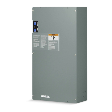
Kohler G220 Guide

Automatic Transfer Switches
Models:
G220
Electrical Controls:
Solid-State
Power Switching Device:
Contactors:
100 and 200 Amperes
TP-6322 9/04
Service and Parts

Product Identification Information
Transfer Switch Identification Numbers
Record the product identification numbers from the
transfer switch nameplate.
Model Designation
Serial Number
Accessory Number Accessory Description

Table of Contents
TP-6322 9/04 Table of Contents
Product Identification Information Inside front cover............................................
Safety Precautions and Instructions I........................................................
Introduction i...............................................................................
List of Related Materials i.....................................................
Service Assistance ii........................................................................
Section 1 General 1.........................................................................
1.1 Purpose 1.............................................................
1.2 Components 1..........................................................
1.3 Nameplate 1...........................................................
1.4 Model Number 2........................................................
1.5 Application Data 2......................................................
Section 2 Operation 3.......................................................................
2.1 Startup 3..............................................................
2.2 Automatic Operation 4...................................................
2.2.1 Failure of Normal Power 4........................................
2.2.2 Restoration of Normal Power 4...................................
2.3 Exerciser Function 5....................................................
2.3.1 Exerciser Switch 5..............................................
2.3.2 Exerciser Power Requirements 6..................................
2.4 Manual Operation 6.....................................................
2.5 External Test Switch 7...................................................
Section 3 Scheduled Maintenance 9..........................................................
3.1 Inspection and Service 10.................................................
3.1.1 General Inspection 10............................................
3.1.2 Internal Inspections, Procedures, and Tests 10.......................
3.2 Testing 12..............................................................
3.2.1 Weekly Generator Set Exercise 12.................................
3.2.2 Monthly Automatic Operation Test 12...............................
3.2.3 Other Tests 13...................................................
3.3 Service Schedule 14.....................................................
Section 4 Troubleshooting 15.................................................................
4.1 General Notes on Connections 16..........................................
4.2 System Power 16........................................................
4.4.1 AC System Voltages 19...........................................
4.4.2 DC Controller Voltages 19.........................................
4.5 Engine Start Circuit 19....................................................
4.6 Exerciser Circuits 20.....................................................
4.7 Contactor Operation 21...................................................
4.7.1 Mechanical Check 21.............................................
4.7.2 Solenoid Troubleshooting 21......................................
4.7.3 After Solenoid Replacement 21....................................
4.7.4 SCN and SCE Contacts 22........................................
4.7.5 NR/ER Relays, Coils, and Controller Circuitry 24.....................
4.8 Controller Operation 24...................................................
4.9 Emergency Source Sensing 25............................................
4.10 Normal Source Sensing 26................................................
Section 5 Drawings and Diagrams 27..........................................................

Table of Contents, continued
TP-6322 9/04Table of Contents
Section 6 Service Part Replacement 31........................................................
6.1 Before and After Servicing Components 32..................................
6.2 Contactor Assembly 32...................................................
6.2.1 Contactor Assembly Removal 32...................................
6.2.2 Contactor Assembly Installation 32.................................
6.3 Solenoid Assembly 33....................................................
6.3.1 Solenoid Assembly Removal 33....................................
6.3.2 Disassembly, 200 Amp Models 33..................................
6.3.3 Reassembly, 200 Amp Models 34..................................
6.3.4 Solenoid Assembly Installation 34..................................
6.4 Microswitch Replacement 35..............................................
6.4.1 100 Amp Models 35..............................................
6.4.2 200 Amp Models 36..............................................
6.5 Controller PCB Assembly 36..............................................
6.5.1 Controller PCB Removal 37.......................................
6.5.2 Controller PCB Installation 37......................................
6.6 Other Service Parts 37...................................................
6.6.1 Other Service Part Removal 37....................................
6.6.2 Other Service Part Installation 38...................................
Section 7 Service Parts 39....................................................................
7.1 General Information 39...................................................
7.1.1 Finding Parts Information 39.......................................
7.1.2 Leads 39.......................................................
7.1.3 Common Hardware 39............................................
7.2 Contactor G220 40.......................................................
7.3 Controls 41.............................................................
7.4 Decals 42...............................................................
7.5 Enclosure, NEMA Type 1 43...............................................
7.6 Enclosure, NEMA Type 3R 44.............................................
7.7 Neutral Lug, 100 Amp 45..................................................
7.8 Neutral Lug, 200 Amp 46..................................................
7.9 Auxiliary Switch 46.......................................................
Appendix A Abbreviations A-1................................................................
Appendix B Common Hardware Application Guidelines A-3.....................................
Appendix C General Torque Specifications A-4.................................................
Appendix D Common Hardware Identification A-5..............................................
Appendix E Common Hardware List A-6.......................................................

TP-6322 9/04 ISafety Precautions and Instructions
Safety Precautions and Instructions
IMPORTANT SAFETY
INSTRUCTIONS. Electromechanical
equipment, including generator sets,
transfer switches, switchgear, and
accessories, can cause bodily harm
and pose life-threatening danger when
improperly installed, operated, or
maintained. To prevent accidents be
aware of potential dangers and act
safely. Read and follow all safety
precautions and instructions. SAVE
THESE INSTRUCTIONS.
This manual has several types of safety
precautions and instructions: Danger,
Warning, Caution, and Notice.
DANGER
Danger indicates the presence of a
hazard that will cause severe
personal injury, death,orsubstantial
property damage.
WARNING
Warning indicates the presence of a
hazard that can cause severe
personal injury, death, or substantial
property damage.
CAUTION
Caution indicates the presence of a
hazard that will or can cause minor
personal injury or property damage.
NOTICE
Notice communicates installation,
operation, or maintenance information
that is safety related but not hazard
related.
Safety decals affixed to the equipment
in prominent places alert the operator
or service technician to potential
hazards and explain how to act safely.
The decals are shown throughout this
publication to improve operator
recognition. Replace missing or
damaged decals.
Accidental Starting
Accidental starting.
Can cause severe injury or death.
Disconnect the battery cables before
working on the generator set.
Remove the negative (--) lead first
when disconnecting the battery.
Reconnect the negative (--) lead last
when reconnecting the battery.
WARNING
Disabling the generator set.
Accidental starting can cause
severe injury or death. Before
working on the generator set or
connected equipment, disable the
generator set as follows: (1) Move the
generator set master switch to the OFF
position. (2) Disconnect the power to
the battery charger. (3) Remove the
battery cables, negative (--) lead first.
Reconnect the negative (--) lead last
when reconnecting the battery. Follow
these precautions to prevent starting of
the generator set by an automatic
transfer switch, remote start/stop
switch, or engine start command from a
remote computer.
Battery
Sulfuric acid in batteries.
Can cause severe injury or death.
Wear protective goggles and
clothing. Battery acid may cause
blindness and burn skin.
WARNING
Battery electrolyte is a diluted
sulfuric acid. Battery acid can cause
severe injury or death. Battery acid
can cause blindness and burn skin.
Always wear splashproof safety
goggles, rubber gloves, and boots
when servicing the battery. Do not
open a sealed battery or mutilate the
battery case. If battery acid splashes in
the eyes or on the skin, immediately
flush the affected area for 15 minutes
with large quantities of clean water.
Seek immediate medical aid in the case
of eye contact. Never add acid to a
battery after placing the battery in
service, as this may result in hazardous
spattering of battery acid.
Explosion.
Can cause severe injury or death.
Relays in the battery charger
cause arcs or sparks.
Locate the battery in a well-ventilated
area. Isolate the battery charger from
explosive fumes.
WARNING
Battery gases. Explosion can cause
severe injury or death. Battery gases
can cause an explosion. Do not smoke
or permit flames or sparks to occur near
a battery at any time, particularly when
it is charging. Do not dispose of a
battery in a fire. To prevent burns and
sparks that could cause an explosion,
avoid touching the battery terminals
with tools or other metal objects.
Remove all jewelry before servicing the
equipment. Discharge static electricity
from your body before touching
batteries by first touching a grounded
metal surface away from the battery. To
avoid sparks, do not disturb the battery
charger connections while the battery
is charging. Always turn the battery
charger off before disconnecting the
battery connections. Ventilate the
compartments containing batteries to
prevent accumulation of explosive
gases.
TP-6322 9/04II Safety Precautions and Instructions
Hazardous Voltage/
Electrical Shock
Hazardous voltage.
Will cause severe injury or death.
Disconnect all power sources before
opening the enclosure.
DANGER
Hazardous voltage.
Can cause severe injury or death.
Operate the generator set only when
all guards and electrical enclosures
areinplace.
Moving rotor.
WARNING
Grounding electrical equipment.
Hazardous voltage can cause
severe injury or death. Electrocution
is possible whenever electricity is
present. Open the main circuit
breakers of all power sources before
servicing the equipment. Configure the
installation to electrically ground the
generator set, transfer switch, and
related equipment and electrical
circuits to comply with applicable codes
and standards. Never contact
electrical leads or appliances when
standing in water or on wet ground
because these conditions increase the
risk of electrocution.
Connecting the battery and the
battery charger. Hazardous voltage
can cause severe injury or death.
Reconnect the battery correctly,
positive to positive and negative to
negative, to avoid electrical shock and
damage to the battery charger and
battery(ies). Have a qualified
electrician install the battery(ies).
Making line or auxiliary
connections. Hazardous voltage
can cause severe injury or death. To
prevent electrical shock deenergize the
normal power source before making
any line or auxiliary connections.
Servicing the transfer switch.
Hazardous voltage can cause
severe injury or death. Deenergize all
power sources before servicing. Open
the main circuit breakers of all transfer
switch power sources and disable all
generator sets as follows: (1) Move all
generator set master controller
switches to the OFF position. (2)
Disconnect power to all battery
chargers. (3) Disconnect all battery
cables, negative (--) leads first.
Reconnect negative (--) leads last when
reconnecting the battery cables after
servicing. Follow these precautions to
prevent the starting of generator sets
by an automatic transfer switch, remote
start/stop switch, or engine start
command from a remote computer.
Before servicing any components
inside the enclosure: (1) Remove all
jewelry. (2) Stand on a dry, approved
electrically insulated mat. (3) Test
circuits with a voltmeter to verify that
they are deenergized.
Servicing the transfer switch
controls and accessories within the
enclosure. Hazardous voltage can
cause severe injury or death.
Disconnect the transfer switch controls
at the inline connector to deenergize
the circuit boards and logic circuitry but
allow the transfer switch to continue to
supply power to the load. Disconnect
all power sources to accessories that
are mounted within the enclosure but
are not wired through the controls and
deenergized by inline connector
separation. Test circuits with a
voltmeter to verify that they are
deenergized before servicing.
Hazardous voltage.
Will cause severe injury or death.
Only authorized personnel should
open the enclosure.
DANGER
Short circuits. Hazardous
voltage/current can cause severe
injury or death. Short circuits can
cause bodily injury and/or equipment
damage.Do not contact electrical
connections with tools or jewelry while
making adjustments or repairs.
Remove all jewelry before servicing the
equipment.
Testing live electrical circuits.
Hazardous voltage or current can
cause severe injury or death. Have
trained and qualified personnel take
diagnostic measurements of live
circuits. Use adequately rated test
equipment with electrically insulated
probes and follow the instructions of the
test equipment manufacturer when
performing voltage tests. Observe the
following precautions when performing
voltage tests: (1) Remove all jewelry.
(2) Stand on a dry, approved electrically
insulated mat. (3) Do not touch the
enclosure or components inside the
enclosure. (4) Be prepared for the
system to operate automatically.
(600 volts and under)
Heavy Equipment
Unbalanced weight.
Improper lifting can cause severe
injury or death and equipment
damage.
Use adequate lifting capacity.
Never leave the transfer switch
standing upright unless it is securely
bolted in place or stabilized.
WARNING

TP-6322 9/04 IIISafety Precautions and Instructions
Moving Parts
Hazardous voltage.
Can cause severe injury or death.
Operate the generator set only when
all guards and electrical enclosures
areinplace.
Moving rotor.
WARNING
Notice
NOTICE
Hardware damage. The transfer
switch may use both American
Standard and metric hardware. Use
the correct size tools to prevent
rounding of the bolt heads and nuts.
NOTICE
When replacing hardware, do not
substitute with inferior grade
hardware. Screws and nuts are
available in different hardness ratings.
To indicate hardness, American
Standard hardware uses a series of
markings, and metric hardware uses a
numeric system. Check the markings
on the bolt heads and nuts for
identification.
NOTICE
Improper operator handle usage.
Use the manual operator handle on the
transfer switch for maintenance
purposes only. Return the transfer
switch to the normal position. Remove
the manual operator handle, if used,
and store it in the place provided on the
transfer switch when service is
completed.
NOTICE
Foreign material contamination.
Cover the transfer switch during
installation to keep dirt, grit, metal drill
chips, and other debris out of the
components. Cover the solenoid
mechanism during installation. After
installation, use the manual operating
handle to cycle the contactor to verify
that it operates freely. Do not use a
screwdriver to force the contactor
mechanism.
NOTICE
Electrostatic discharge damage.
Electrostatic discharge (ESD)
damages electronic circuit boards.
Prevent electrostatic discharge
damage by wearing an approved
grounding wrist strap when handling
electronic circuit boards or integrated
circuits. An approved grounding wrist
strap provides a high resistance (about
1 megohm), not a direct short,to
ground.

TP-6322 9/04IV Safety Precautions and Instructions
Notes

TP-6322 9/04 iIntroduction
Introduction
This manual provides service and parts information for
KohlerrModel G220 transfer switches with solid-state
electrical controls and 100 and 200 ampere contactor
power switching devices. This manual includes
operation, troubleshooting, repair, and maintenance
procedures for the transfer switch including the power
switching device and electrical controls. This manual is
intended for the use only by persons trained and
qualified to work on electrical equipment.
Information in this publication represents data available
at the time of print. Kohler Co. reserves the right to
change this literature and the products represented
without notice and without any obligation or liability
whatsoever.
Read this manual and carefully follow all procedures
and safety precautions to ensure proper equipment
operation and to avoid bodily injury. Read and follow the
Safety Precautions and Instructions section at the
beginning of this manual. Keep this manual with the
equipment for future reference.
The equipment service requirements are very important
to safe and efficient operation. Inspect parts often and
perform required service at the prescribed intervals.
Obtain service from an authorized service distributor/
dealer to keep equipment in top condition.
List of Related Materials
Separate literature contains operation and installation
information not provided in this manual. The following
table lists the available literature part numbers.
Document
Part
Number
Model G220 Operation and Installation Manual TP-6321
Specification Sheet G11-88

TP-6322 9/04ii Service Assistance
Service Assistance
For professional advice on generator power
requirements and conscientious service, please contact
your nearest Kohler distributor or dealer.
DConsult the Yellow Pages under the heading
Generators—Electric
DVisit the Kohler Power Systems website at
KohlerPowerSystems.com
DLook at the labels and stickers on your Kohler product
or review the appropriate literature or documents
included with the product
DCall toll free in the US and Canada 1-800-544-2444
DOutside the US and Canada, call the nearest regional
office
Headquarters Europe, Middle East,Africa
(EMEA)
Kohler Power Systems
ZI Senia 122
12, rue des Hauts Flouviers
94517 Thiais Cedex
France
Phone: (33) 1 41 735500
Fax: (33) 1 41 735501
Asia Pacific
Power Systems Asia Pacific Regional Office
Singapore, Republic of Singapore
Phone: (65) 6264-6422
Fax: (65) 6264-6455
China
North China Regional Office, Beijing
Phone: (86) 10 6518 7950
(86) 10 6518 7951
(86) 10 6518 7952
Fax: (86) 10 6518 7955
East China Regional Office, Shanghai
Phone: (86) 21 6288 0500
Fax: (86) 21 6288 0550
India, Bangladesh, Sri Lanka
India Regional Office
Bangalore, India
Phone: (91) 80 3366208
(91) 80 3366231
Fax: (91) 80 3315972
Japan, Korea
North Asia Regional Office
Tokyo, Japan
Phone: (813) 3440-4515
Fax: (813) 3440-2727
Latin America
Latin America Regional Office
Lakeland, Florida, USA
Phone: (863) 619-7568
Fax: (863) 701-7131

TP-6322 9/04 1Section 1 General
Section 1 General
1.1 Purpose
An automatic transfer switch (ATS) transfers electrical
loads from a normal (preferred or utility) source of
electrical power to an emergency (standby or
replacement) source when the normal source fails to
maintain a minimum power quality level.
When the normal source fails, the ATS signals the
emergency source generator set to start. When the
emergency source reaches a minimum quality level, the
ATS transfers the load from the normal source to the
emergency source. The ATS continuously monitors the
normal source and transfers the load back to the normal
source when the normal source returns. After
transferring the load back to the normal source, the ATS
removes the generator start signal, allowing the
generator set to shut down.
1.2 Components
The ATS documented in this manual contains several
components. See Figure 1-1. The contactor power
switching device connects the load to the normal or
emergency sources of power. The electrical controls
monitor power sources, control the contactor, and signal
the generator to start when needed. The exerciser
switch controls the operation of the exerciser function.
The contactor power switching device transfers power
from the normal or emergency power sources to the
load. The electrical controls electrically actuate the
contactor to select a power source, and the contactor
mechanically latches in the selected position. The
contactor also includes a provision for manual operation
in emergency nonpowered conditions.
1 43
55990101
2
1. Power switching device (contactor)
2. Enclosure
3. Electrical controls (solid-state)
4. Enclosure cover
5. Exerciser switch
Figure 1-1 ATS Components
The contactor power switching device uses two sets of
multipole contacts. See Figure 1-2. One set of contacts
connects the load to the normal source and the other set
connects the load to the emergency source. The
double-throw, inherently interlocked design of the
contactor prevents simultaneous closing of both sets of
contacts and cross-coupling of power sources.
Power
Switching
Device
To Load
Automatic Transfer Switch
Electrical
Controls
Normal
(Utility)
Power
Emergency
(Generator)
Power Generator
Start Generator
TS-002
Figure 1-2 Typical ATS Block Diagram
1.3 Nameplate
A nameplate attached to the inside of the enclosure door
or cover includes a model number, a serial number,
ratings, and other information that may be needed for
operation, installation, service, or to order parts. See
Figure 1-3.
ENCLOSURE
POLES HERTZ
SERIAL NO.
AMPS
WIRES
MODEL
PHASE
ACCESSORIES:
TS-003
1
3
TRANSFER SWITCH
VOLTS
2
KOHLER CO. KOHLER WI, USA
r
FOR EMERGENCY SYSTEMS
1. Model number
2. Factory-installed accessory numbers
3. Serial number
Figure 1-3 Typical Transfer Switch Nameplate

TP-6322 9/042 Section 1 General
Copy the model number, serial number, and accessory
information from the nameplate into the spaces
provided inside the front cover for use when requesting
service or parts. Copy the model number into the blank
spaces in Figure 1-5 and use the figure to interpret the
model number code.
Copy the model number and serial number from the
nameplate into the spaces provided in the Service
Assistance section of this manual for use when
requesting service or parts.
1.4 Model Number
See Figure 1-5 to interpret the transfer switch model
number.
1.5 Application Data
See Figure 1-4 for the range of wire sizes for transfer
switch power terminals.
UL-Listed Solderless Screw-Type Terminals
for External Power Connections
Switch
R
a
t
i
n
g
Normal, Emergency, and Load Terminals
Rating
(amps) Cables per Pole Range of Wire Sizes
100 1 #8 to 3/0 (copper or aluminum)
200 1 #8 to 3/0 (copper only)
Figure 1-4 Application Data
Record the transfer switch part number in the boxes below. The transfer switch part number defines characteristics and ratings
as explained in the accompanying chart.
Model Controls Voltage and Frequency Poles Wires Enclosure Current Rating
KohlerrModel Number Key
This chart explains the Kohlerrtransfer switch model number code. The sample model number
shown is for a Model G220 automatic transfer switch that uses a 250-volt maximum contactor
power switching device with solid-state electrical controls rated at 240 volts, 60 hertz, 1 phase,
2 pole, and 3 wires in a NEMA Type 3R enclosure with a current rating of 100 amperes. Not all
possible combinations are available.
SAMPLE PART NUMBER
Model
G220: Model G220 transfer switch, 250-volt maximum contactor
Electrical Controls
1: Solid-state
Voltage and Frequency
63: 220 Volt, 50 Hz
64: 240 Volt, 60 Hz
Number of Poles and Phases
2: 2 Pole, 1 Phase
Number of Wires
3: 3 Wire
Enclosure
3=NEMAtype3R
Current Rating
Numbers indicate the current rating of the switch in amperes.
G220-164233-0100
Figure 1-5 Transfer Switch Model Number Code

TP-6322 9/04 3Section 2 Operation
Section 2 Operation
Hazardous voltage.
Will cause severe injury or death.
Disconnect all power sources before
opening the enclosure.
DANGER
Have preventive maintenance performed on the
transfer switch at regular intervals after installation. See
Section 3 for instructions.
Contact an authorized distributor/dealer to inspect and
service the transfer switch when any wear, damage,
deterioration, or malfunction of the transfer switch or its
components is evident or suspected; do not energize
the switch.
2.1 Startup
Perform the following powerup procedure after
maintenance or service of the standby system that
requires disconnection of power sources from the
transfer switch, not for initial startup.
For initial startup, follow the instructions in the
Installation section in the operation and installation
manual for the transfer switch. See List of Related
Materials in the Introduction section of this manual for
the manual part number.
Read and understand documentation provided with the
switch and labels affixed to the switch. Review the
operation of installed accessories.
Follow the steps below to power up the transfer switch
and prepare it for automatic operation.
Powerup Procedure
1. Place the generator set master switch in the OFF
position to prevent starting the generator set.
2. Disconnect both the normal and emergency power
sources by opening circuit breakers or switches
leading to the transfer switch.
3. Open the enclosure and check that the contactor
wiring harness is connected to the electrical
controls at connector P1. See Figure 4-2.
4. Follow the manual operation procedure to prepare
the transfer switch for automatic operation. See
Section 2.4 for instructions.
5. Replace the transfer switch enclosure cover. Lock
NEMA type 3R enclosures with a padlock. Replace
and tighten the fastening screws on the enclosure
cover.
6. Prepare the standby generator set for operation.
Check the oil level, coolant level, fuel supply,
batteries, and items specified by the generator set
Prestart Checklist or similar instructions in the
operation manual.
7. Place the generator set master switch in the AUTO
position. The generator set should start.
8. When loads are ready to be energized, close circuit
breakers or switches leading to the transfer switch.
Note: When applying power to the transfer switch
whose electrical controls have lost power,
the engine-start contact remains closed and
the engine start LED stays off, signaling the
generator to run at least until the ATS’s time
delay engine cooldown (TDEC) ends.
9. Perform an automatic operation test. With normal
power present, disconnect the normal power
source and verify that the system responds as
described in Section 2.2.1, starting the generator
set automatically and transferring the load to the
emergency power source. When the transfer
switch has transferred the load to the emergency
source, reconnect the normal power source and
verify that the system operates as described in
Section 2.2.2, retransferring the load to the normal
source and shutting down the generator set after
TDEC.

TP-6322 9/044 Section 2 Operation
2.2 Automatic Operation
The ATS controller monitors the normal and emergency
power sources and determines when a power source
has failed or is acceptable and controls the system
accordingly. See Figure 4-2. Failure of a power source
occurs when its voltage on one or more phases falls
below the dropout voltage level. A power source is
acceptable when its voltage on sensed phases rise
above the pickup voltage level and stay above the
dropout voltage level. A power source is restored when
it becomes acceptable again after failure. Typical ATS
operation occurs in two separate automatic sequences.
DFailure of normal power and the resulting transfer to
emergency power.
DRestoration of normal power and the resulting
transfer back to normal power.
2.2.1 Failure of Normal Power
The main controller circuit board monitors phase A-C of
the normal power source. The normal available (NA)
LED on the main controller circuit board lights when the
normal power source is acceptable.
On single-phase switches the jumper JP3 connects
terminals GND and 3PH on the main controller circuit
board. See Figure 2-1. The controller considers the
normal source unacceptable when the normal source
voltage on phase A-C drops below the single-phase
dropout specification and acceptable when it rises
above the single-phase pickup specification.
362140
123 123456
NA
NB
NC
NSC
TEST
GND
ESC
GND
3PH
TB1
TB2
JP2 JP1 JP3
MAIN CONTROLLER CIRCUIT BOARD
Figure 2-1 Single-phase Configuration
When the normal power source fails, the normal relay
(NR) on the main controller circuit board is no longer
held, the NA LED turns off, and the controller starts a
time delay called time delay engine start (TDES). TDES
prevents unnecessary generator startup during short
utility power interruptions. The controller maintains
internal control circuits including the plant exerciser
setting for up to 90 seconds without the normal or
emergency power source. If the normal power source is
restored before TDES ends, the controller resets the
time delay. If the normal power failure persists and
TDES ends, the controller issues a signal to start the
standby (emergency) generator to produce the
emergency power source by closing the engine-start
contact between terminals ES3 and ES4 and the engine
start (ES) LED on the main controller circuit board turns
off.
After signalling the generator to start, the controller
monitors the voltage on phase A-C of the emergency
source. The emergency acceptable (EA) LED on the
main controller circuit board lights when the voltage
rises above the emergency source pickup specification.
The controller considers the emergency source
acceptable and the EA LED remains lit when the
emergency source voltage remains above the
emergency source dropout level specification. When
the emergency source becomes available, the
controller starts a time delay called time delay
normal-to-emergency (TDNE). TDNE allows
emergency power source stabilization before load
connection. When TDNE ends, the controller lights the
ER LED and energizes the emergency relay (ER). The
emergency relay signals the contactor to connect the
load to the emergency source operating the contactor
solenoid TS through a bridge rectifier BR and
coil-clearing contact SCE. When the contactor moves
away from the normal position, coil-clearing contact
SCE opens to remove power from the solenoid. The
contactor mechanism’s inertia carries it through the top
of the cycle and into the emergency position. A
contactor mechanically latches in the emergency
position until normal power source restoration and
stabilization.
2.2.2 Restoration of Normal Power
When the normal power source is restored, the
controller lights the NA LED and starts a time delay
called time delay emergency-to-normal (TDEN). If the
normal source fails before TDEN ends, the NA LED
turns off and the time delay resets. TDEN ensures
normal power source stabilization before load
reconnection.
When the controller determines that the normal power
source has maintained an acceptable level and TDEN
ends, the controller signals the contactor to reconnect
the load to the normal source. It does this by lighting the
NR LED and energizing the NR relay to operate the
contactor solenoid TS through bridge rectifier BR and
coil-clearing contact SCN. When the contactor moves
away from the emergency position, coil-clearing contact
SCN opens to remove power from the solenoid. The

TP-6322 9/04 5Section 2 Operation
contactor mechanism’s inertia carries it through the top
of the cycle and into the normal position. The contactor
is mechanically latched in the normal position until the
next normal power source failure. The controller starts a
time delay called time delay engine cooldown (TDEC).
TDEC allows the engine and generator to run unloaded
and cool down before shutdown. When TDEC ends, the
controller signals the generator set to shut down by
opening the engine-start contact between terminals
ES3 and ES4 and the ES LED on the main controller
circuit board lights. When the generator set shuts down,
the EA LED turns off.
2.3 Exerciser Function
The exerciser function, when enabled, automatically
starts and runs the generator set unloaded (the ATS
does not transfer the load to the emergency source) for
20 minutes once a week. Exercising the generator set
helps to ensure that the generator set starts when
emergency power is needed. An exerciser switch
selects exerciser functions. Automatic operation
overrides the exerciser function. The loss of all power
sources for more than 90 seconds will result in the loss
of the exerciser set time. See Section 2.3.2.
2.3.1 Exerciser Switch
An exerciser switch is located inside the ATS enclosure.
See Figure 1-1 and Figure 2-2.
5990202
EXERCISER
1 2
3
4
1. Exerciser switch
2. Set position (momentary, up)
3. Disable position (down)
4. Enable position (middle)
Figure 2-2 Exerciser Switch
Hazardous voltage.
Will cause severe injury or death.
Only authorized personnel should
open the enclosure.
DANGER
Short circuits. Hazardous voltage/current can cause
severe injury or death. Short circuits can cause bodily injury
and/or equipment damage.Do not contact electrical
connections with tools or jewelry while making adjustments or
repairs. Remove all jewelry before servicing the equipment.
Note: The exerciser switch is set during installation and
normally does not require adjustment. Line
voltage is present on some components inside
the ATS enclosure when power sources are
applied. Only trained and qualified personnel
should open the ATS enclosure when power is
present. Read and follow all safety decals inside
the enclosure and avoid contact with line voltage.
The exerciser switch selects the following exerciser
functions when power is available. See Section 2.3.2.
DSet ( ). Placing the switch in the momentary
(spring-loaded) set position and releasing the switch
to the run position sets the exerciser: the exerciser’s
internal one-week timer is set and the exerciser starts
and runs the generator set for a 20-minute period.
Subsequent weekly 20-minute exercise periods start
at the same day and time the exerciser was released
from the set position.
DEnable ( ). Placing the switch is the enable position
causes the exerciser to start and run the generator set
unloaded for 20 minutes on the same day and time
each week the exerciser was last set.
DDisable ( ). Placing the switch in the disable
position prevents the exerciser from starting and
running the generator. The exerciser’s internal
one-week timer continues to run and the exerciser’s
set day and time are not lost. The ATS, however,

TP-6322 9/046 Section 2 Operation
starts the generator automatically when the normal
power source fails.
Replace the enclosure cover on the ATS enclosure and
tighten the screws that hold it in place after viewing or
making changes to the exerciser switch setting.
2.3.2 Exerciser Power Requirements
An internal one-week timer for the exerciser function
maintains its setting for up to 90 seconds after power
loss of both the normal and emergency sources. When
the normal power source fails, the generator must start
and run to provide emergency power within
approximately 90 seconds or the system loses the
previously set day and time and the exerciser is set to
the day and time that either power source returns. Then,
if the exerciser switch is in the Enable ( ) position, the
controller starts and runs the generator set unloaded for
20 minutes one week from the day and time of power
source return and on subsequent weeks at the same
day and time.
2.4 Manual Operation
To test or troubleshoot the transfer switch, manually
operate the contactor using the procedure described
below.
Accidental starting.
Can cause severe injury or death.
Disconnect the battery cables before
working on the generator set.
Remove the negative (--) lead first
when disconnecting the battery.
Reconnect the negative (--) lead last
when reconnecting the battery.
WARNING
Disabling the generator set. Accidental starting can
cause severe injury or death. Before working on the
generator set or connected equipment, disable the generator
set as follows: (1) Move the generator set master switch to the
OFF position. (2) Disconnect the power to the battery charger.
(3) Remove the battery cables, negative (--) lead first.
Reconnect the negative (--) lead last when reconnecting the
battery. Follow these precautions to prevent starting of the
generator set by an automatic transfer switch, remote
start/stop switch, or engine start command from a remote
computer.
Hazardous voltage.
Will cause severe injury or death.
Only authorized personnel should
open the enclosure.
DANGER
Servicing the transfer switch. Hazardous voltage can
cause severe injury or death. Deenergize all power sources
before servicing. Open the main circuit breakers of all transfer
switch power sources and disable all generator sets as
follows: (1) Move all generator set master controller switches
to the OFF position. (2) Disconnect power to all battery
chargers. (3) Disconnect all battery cables, negative (--) leads
first. Reconnect negative (--) leads last when reconnecting the
battery cables after servicing. Follow these precautions to
prevent the starting of generator sets by an automatic transfer
switch, remote start/stop switch, or engine start command
from a remote computer. Before servicing any components
inside the enclosure: (1) Remove all jewelry. (2) Stand on a
dry, approved electrically insulated mat. (3) Test circuits with a
voltmeter to verify that they are deenergized.
Manual Operation Procedure
1. Prevent the generator set that provides the
emergency power source to the transfer switch
from starting.
a. Move the generator set master switch to the
OFF position.
b. Disconnect power to the generator engine start
battery charger, if installed.
c. Disconnect all generator engine start batteries,
negative (--) leads first.
2. Disconnect or turn off both the normal and
emergency power sources by opening upstream
circuit breakers or switches to the transfer switch.
Note: The manual operation handle is provided for
maintenance purposes only. Do not attempt
to use the manual operation handle to
transfer the load.
3. Remove the cover on front of the transfer switch
enclosure.

TP-6322 9/04 7Section 2 Operation
4. Slide the large end of the manual operation handle
over the manual operation lever on the left side of
the contactor. See Figure 2-3. Move the handle up
to place the transfer switch in the Normal Source
position, or down to place the contactor in the
Emergency Source position.
Note: Do not attempt to move the manual
operation lever without using the handle.
5. Move the handle up to place the transfer switch in
the Normal Source position for normal operation.
6. Remove the handle and store it in a convenient
location near the transfer switch.
7. Replace the cover on the transfer switch enclosure
and tighten the screws that hold it in place.
8. Reconnect power supplies to the transfer switch.
Note: When power is applied to the transfer
switch, the engine start contacts remain
closed until Time Delay Engine Cooldown
(TDEC) ends.
9. Return the generator set to automatic operation.
a. Reconnect the generator engine start battery
cables, negative (--) leads last.
b. Reconnect power to the generator engine start
battery charger, if installed.
c. Move the generator set master switch to the
AUTO (automatic) position. The generator set
may start and run until the Time Delay Engine
Cooldown (TDEC) ends (see Note above).
1. Manual operation handle
2. Manual operation lever tp6223
2
43
7
8
CN
CE
NL1 NL2
EL2EL1
SCN
C
NO
NC
SCE
C
NC
NO
1
Figure 2-3 Contactor with Manual Operation Handle
2.5 External Test Switch
A provision on the main controller circuit board allows
the connection of a customer-supplied, normally closed
external test switch. This test switch connects between
the TEST and GND terminals after cutting the jumper
JP2 on the controller circuit board. See Figure 2-4.
When the test switch contact is open, normal-source
single-phase power is disconnected from the controller,
and the controller follows the same sequence of
operation as when the normal source fails.
362140
123 123456
NA
NB
NC
NSC
TEST
GND
ESC
GND
3PH
TB1
TB2
TEST
SWITCH
JP2 JP1
NC
JP3
MAIN CONTROLLER CIRCUIT BOARD
Figure 2-4 External Test Switch

TP-6322 9/048 Section 2 Operation
Notes

TP-6322 9/04 9Section 3 Scheduled Maintenance
Section 3 Scheduled Maintenance
Scheduled preventive maintenance ensures safe and
reliable operation and extends the life of the transfer
switch. Preventive maintenance includes periodic
testing, cleaning, inspecting, and replacing of worn or
missing components.
A local authorized distributor/dealer can provide
complete preventive maintenance and services to keep
the transfer switch in top condition. Contact a local
distributor/dealer for additional information. See the
Service Assistance section in the Introduction for how to
locate a local distributor/dealer.
Read this entire section carefully before attempting any
maintenance or service. Unless otherwise specified,
have maintenance or service performed by an
authorized distributor/dealer that has trained and
qualified personnel who follow all applicable codes and
standards.
Keep records of all maintenance or service.
Replace all barriers and close and lock the enclosure
door after maintenance or service and before reapplying
power.
Accidental starting.
Can cause severe injury or death.
Disconnect the battery cables before
working on the generator set.
Remove the negative (--) lead first
when disconnecting the battery.
Reconnect the negative (--) lead last
when reconnecting the battery.
WARNING
Disabling the generator set. Accidental starting can
cause severe injury or death. Before working on the
generator set or connected equipment, disable the generator
set as follows: (1) Move the generator set master switch to the
OFF position. (2) Disconnect the power to the battery charger.
(3) Remove the battery cables, negative (--) lead first.
Reconnect the negative (--) lead last when reconnecting the
battery. Follow these precautions to prevent starting of the
generator set by an automatic transfer switch, remote
start/stop switch, or engine start command from a remote
computer.
Hazardous voltage.
Will cause severe injury or death.
Only authorized personnel should
open the enclosure.
DANGER
Hazardous voltage.
Can cause severe injury or death.
Operate the generator set only when
all guards and electrical enclosures
areinplace.
Moving rotor.
WARNING
Grounding electrical equipment. Hazardous voltage can
cause severe injury or death. Electrocution is possible
whenever electricity is present. Open the main circuit
breakers of all power sources before servicing the equipment.
Configure the installation to electrically ground the generator
set, transfer switch, and related equipment and electrical
circuits to comply with applicable codes and standards. Never
contact electrical leads or appliances when standing in water
or on wet ground because these conditions increase the risk of
electrocution.
Short circuits. Hazardous voltage/current can cause
severe injury or death. Short circuits can cause bodily injury
and/or equipment damage.Do not contact electrical
connections with tools or jewelry while making adjustments or
repairs. Remove all jewelry before servicing the equipment.
Testing live electrical circuits. Hazardous voltage or
current can cause severe injury or death. Have trained and
qualified personnel take diagnostic measurements of live
circuits. Use adequately rated test equipment with electrically
insulated probes and follow the instructions of the test
equipment manufacturer when performing voltage tests.
Observe the following precautions when performing voltage
tests: (1) Remove all jewelry. (2) Stand on a dry, approved
electrically insulated mat. (3) Do not touch the enclosure or
components inside the enclosure. (4) Be prepared for the
system to operate automatically.
(600 volts and under)

TP-6322 9/0410 Section 3 Scheduled Maintenance
Servicing the transfer switch. Hazardous voltage can
cause severe injury or death. Deenergize all power sources
before servicing. Open the main circuit breakers of all transfer
switch power sources and disable all generator sets as
follows: (1) Move all generator set master controller switches
to the OFF position. (2) Disconnect power to all battery
chargers. (3) Disconnect all battery cables, negative (--) leads
first. Reconnect negative (--) leads last when reconnecting the
battery cables after servicing. Follow these precautions to
prevent the starting of generator sets by an automatic transfer
switch, remote start/stop switch, or engine start command
from a remote computer. Before servicing any components
inside the enclosure: (1) Remove all jewelry. (2) Stand on a
dry, approved electrically insulated mat. (3) Test circuits with a
voltmeter to verify that they are deenergized.
Servicing the transfer switch controls and accessories
within the enclosure. Hazardous voltage can cause
severe injury or death. Disconnect the transfer switch
controls at the inline connector to deenergize the circuitboards
and logic circuitry but allow the transfer switch to continue to
supply power to the load. Disconnect all power sources to
accessories that are mounted within the enclosure but are not
wired through the controls and deenergized by inline
connector separation. Test circuits with a voltmeter to verify
that they are deenergized before servicing.
NOTICE
Hardware damage. The transfer switch may use both
American Standard and metric hardware. Use the correct size
tools to prevent rounding of the bolt heads and nuts.
NOTICE
When replacing hardware, do not substitute with inferior
grade hardware. Screws and nuts are available in different
hardness ratings. To indicate hardness, American Standard
hardware uses a series of markings, and metric hardware
uses a numeric system. Check the markings on the bolt heads
and nuts for identification.
NOTICE
Electrostatic discharge damage. Electrostatic discharge
(ESD) damages electronic circuit boards. Prevent
electrostatic discharge damage by wearing an approved
grounding wrist strap when handling electronic circuit boards
or integrated circuits. An approved grounding wrist strap
provides a high resistance (about 1 megohm), not a direct
short, to ground.
3.1 Inspection and Service
Contact an authorized distributor/dealer to inspect and
service the transfer switch when any wear, damage,
deterioration, or malfunction of the transfer switch or its
components is evident or suspected.
3.1.1 General Inspection
External Inspection. Keep the transfer switch clean
and in good condition by performing a weekly general
external inspection of the transfer switch for any
condition of vibration, leakage, excessive noise,
temperature, contamination, or deterioration. Remove
accumulations of dirt, dust, and other contaminants from
the transfer switch’s exterior with a vacuum cleaner or
by wiping with a dry cloth or brush. Do not use
compressed air to clean the switch because it can cause
debris to lodge in and damage the components.
Replace any worn, missing, or broken external
components with manufacturer-recommended
replacement parts. Contact a local authorized
distributor/dealer for part information and part ordering.
Tighten loose external hardware.
3.1.2 Internal Inspections, Procedures,
and Tests
Internal Inspection. Disconnect all power sources,
remove the transfer switch enclosure cover, and inspect
internal components every six months (more frequently
in dusty or dirty areas) or when any condition noticed
during an external inspection may have affected internal
components. Inspect for:
DAccumulations of dirt, dust, moisture, or other
contaminants
DSigns of corrosion
DWorn, missing, or broken components
DLoose hardware
DWire or cable insulation deterioration, cuts, or
abrasion
DSigns of overheating or loose connections:
discoloration of metal, melted plastic, or a burning
odor
DOther evidence of wear, damage, deterioration, or
malfunction of the transfer switch or its components.
Cleaning. Remove contaminants from internal
components with a vacuum cleaner or by wiping with a
dry cloth or brush if possible. Do not use compressed air
to clean the switch because it can cause debris to lodge
in and damage the components.
Table of contents
Other Kohler Switch manuals

Kohler
Kohler ZCS-6 User manual

Kohler
Kohler 1041995 User manual

Kohler
Kohler M340+ Building instructions

Kohler
Kohler RSB Series Instruction Manual

Kohler
Kohler KSS User manual

Kohler
Kohler KBS Instruction Manual

Kohler
Kohler KEP User manual

Kohler
Kohler ZCM-6 User manual

Kohler
Kohler KCT MPAC 1000 Instruction Manual

Kohler
Kohler ZCS series Instruction Manual

Kohler
Kohler GLS-1 User manual

Kohler
Kohler KGS Specification sheet

Kohler
Kohler KCS Instruction Manual

Kohler
Kohler KEP User manual

Kohler
Kohler MMS Instruction Manual

Kohler
Kohler KSS Series User manual

Kohler
Kohler Decision-Maker MPAC 750 Instruction Manual

Kohler
Kohler VERSO50 User manual

Kohler
Kohler RXT Instruction Manual

Kohler
Kohler RDT User manual