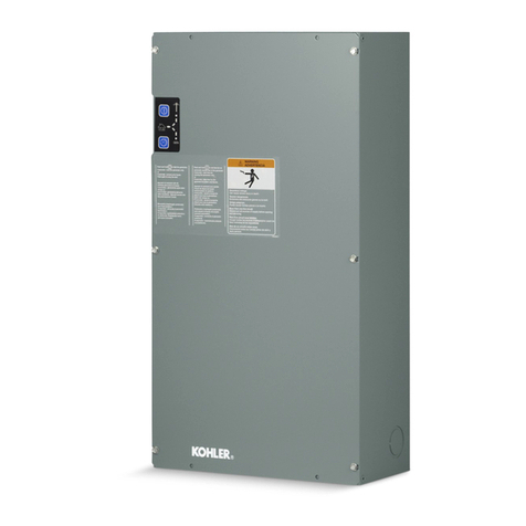
Kohler 340 KN Series Instruction Manual

NonautomaticTransferSwitches
Models:
340
KN-Series
Logic:
Relay
Contactor:
30-4000 Amperes
TP-5585 3/92a
Operation and
Installation
U.S.A.Plant ISORegistered

Contents
Safety Precautions& Instructionsi..........................
Ratings 1...................................................
Installation 1...............................................
Unpacking 1..............................................
Lifting 1..................................................
Mounting 2...............................................
Line Connections2...................................................
AuxiliaryConnections4....................................
Engine-Starting Connections5.............................
FunctionalTests5........................................
ManualOperation Check 5.................................
Voltage Checks 8.........................................
ElectricalOperation Test9.................................
SwitchPosition & Source Indicators 11.......................
TransferSwitchPosition Lamps11......................................
SourceAvailable Lamps11.............................................
Control Switches 11..........................................
“TransferTo”Normal-Emergency 11.....................................
GeneratorStop-Start(ifequipped)12....................................
AlarmSilenceSwitch(ifequipped)12....................................
TransferSwitch Operation 12.................................
NormalPowerLoss 12.....................................
NormalPowerReturn 13....................................
Wiring Diagrams& Drawings 15..............................
Interconnection Diagrams15................................
EnclosureDimensions15...................................
ContactorWiring 15........................................
Schematics 15.............................................
Wiring Diagrams15........................................

Safety Precautions
i
SafetyPrecautions&Instructions
ATransferSwitch,like anyother
electro-mechanicaldevicecan posepotential
dangerstolife and limbifimproperly
maintainedorimprudentlyoperated.Thebest
safeguardsagainstaccidentareto be ever
mindfulofthepotentialdangersand toalways
use good common sense. Inthe interestof
safety,some generalprecautionsrelating to
operation ofatransferswitchfollow.Keep
theseinmind.Thismanualcontains several
typesofsafetyprecautionswhich are
explained below.Examplesofvarious
precautionarystatementsusedinthismanual
are alsoshown.
DANGER
Dangerisused toindicatethe presence ofa
hazardwhichwill causesevere personal
injury,death,orsubstantialpropertydamage
if the warning isignored.
WARNING
Warning isused toindicatethe presence ofa
hazardwhichcan causesevere personal
injury,death,orsubstantialpropertydamage
if the warning isignored.
CAUTION
Caution isused toindicatethe presence ofa
hazardwhichwillorcancauseminorpersonal
injuryorpropertydamage if the warning is
ignored.
NOTE
Noteisused to notifypeople ofinstallation,
operation,ormaintenanceinformation which
isimportantbutnothazard-related.
HAZARDOUS VOLTAGE/
ELECTRICALSHOCK
Disconnectpowersourcesbefore
servicing.Barriermustbe installed after
adjustments,maintenance,orservicing.
WARNING
Hazardous voltage.
Cancause severeinjuryor death.
(under 600 Volt)
Disconnectpowersourcesbefore
servicing.Barriermustbe installed after
adjustments,maintenance,orservicing.
DANGER
Hazardous voltage.
Will cause severeinjuryor death.
(600 Volt and above)

ii Safety
Do notopen enclosure until all power
sourcesare disconnected.
WARNING
Hazardous voltage.
Cancause severeinjuryor death.
(under 600 Volt)
Do notopen enclosure until all power
sourcesare disconnected.
DANGER
Hazardous voltage.
Will cause severeinjuryor death.
(600 Volt and above)
Hazardous voltage cancause severe
injuryor death. Disconnectset fromload by
opening line circuitbreakerorby
disconnecting generatoroutputleadsfrom
transferswitch and heavilytaping endsof
leads.Ifhigh voltage istransferred toload
during test, personal injuryand equipment
damage mayresult. The GENERATOR
SAFEGUARD BREAKERMUSTNOTBE
USEDINPLACEOFLINECIRCUIT
BREAKER!
Hazardous voltage cancause severe
injuryor death. The TransferSwitchis
energized;proceed withcare!High voltage
can cause personal injury,damage
equipment, orlead tofuturefailures.Remove
watch,rings,andjewelrythatcan causeshort
circuits.
Hazardous voltage cancause severe
injuryor death. The TransferSwitchis
energized;proceed withcare!High Voltage
can cause personal injury,damage
equipment, orlead tofuturefailures.Remove
rings,watches,and jewelrythatcan cause
shortcircuits.Thistestshouldbedoneonlyby
a qualified electrician.Followmanufacturer’s
instructionswhen operating tester.
Hazardous voltage cancause severe
injuryor death. To prevent the possibilityof
electricalshock,de-energizethe normal
powersourceto be connectedtotheTransfer
Switch beforemaking anyline orauxiliary
connections.
Hazardous voltage cancause severe
injuryor death. De-energize both normal
and emergency powersourcesbefore
proceeding.MoveGeneratorMasterSwitch
on controllertoOFF position and disconnect
batterynegative(--) beforeworking on
transferswitch!Turnthe transferswitch
selectorswitchtothe OFF position.

Safety Precautions
iii
Hazardous voltage cancause severe
injuryor death. Disconnectinnerpanel
harness atin-line connector.Thiswill
de-energizecircuitboard and logic circuitry,
butallowtransferswitchtocontinue tosupply
utilitypowerto necessarylighting and
equipment.Hazardousvoltagewillexistifany
accessoriesmounted toinnerpanelareNOT
wired through and de-energized byharness
separation.Such accessoriesmaybe atline
voltage.
Hazardous voltage cancause severe
injuryor death. Keep everyone awayfrom
the setand take precautionsto prevent
unqualified personnelfromtampering.Have
the setand electricalcircuits serviced onlyby
qualified technicians.Wiring should be
inspected at the recommended interval
shownintheserviceschedule--replaceleads
thatarefrayed orin poorcondition.Do not
operate electricalequipmentwhen standing
inwater,on wetground,orwhen yourhands
arewet.
Hazardous voltage cancause severe
injuryor death. Disconnectharness plug
beforeinstalling anyaccessoriesinvolving
connection totransformerassemblyprimary
terminals.Terminalsare atline voltage!
NOTE
HARDWAREDAMAGE!Transferswitchmay
make use ofbothAmerican standard and
metrichardware.Besureto usethe correct
sizetoolsto preventrounding ofboltheads
and nuts.
NOTE
Amanualoperatorhandleisprovided on the
TransferSwitchformaintenance purposes
only.ReturntheTransferSwitchtotheNormal
position.Removemanualoperatorhandle(if
used)andstoreitontheTransferSwitchinthe
place provided when serviceis completed.

Installation
1
Ratings
The rating label isattached tothe transfer
switch.Datarelatingto eachspecific switchis
included on the nameplate.Unitinstallation
mustnotexceed the rated capacityof the
switch as shownonthe nameplate.
Forlocation of the transferswitchinthe
systemseeFigure 1.The switchshouldbeas
closeaspossibletothecriticalelectricalloads
connected toit.
Normal
Source
Transfer
Switch
Emergency
Source
Loads
Figure 1. TransferSwitch Location
Installation
Kohlertransferswitchesarefactorywiredand
tested. Installation requiresmounting,
connection ofutility,load,emergency cables
and anyauxiliary contact/controlcircuits.Do
notremove protective packing until readyfor
completeinstallation.Protectswitch atall
timesfromexcessivemoisture,construction
grit, and metalchips.
Unpacking
Carefullyunpackoruncrateswitch and check
fordamage.Reportanydamageimmediately
tothe KohlerDistributor.
Lifting
Anylifting devicesmustbe attached tothe
switch’smountingholesorliftingeyesonly.Do

asco
Installation Procedures
2
notlift the switch atanyotherpoints.Protect
arcbarriersfromimpactatall times.
Mounting
All enclosed switcheshavethe controlpanel
mounted on the cabinetdoor.Foropen-type
switches,mount the controlpaneltothe right
of the transferswitch.
Disconnect power sources before servicing.
Barrier must be installed after adjustments,
maintenance, or servicing.
WARNING
Hazardous voltage.
Can cause severe injury or death.
(under 600 Volt)
Hazardous voltage cancause severe
injuryordeath.De-energizebothnormaland
emergency powersourcesbefore
proceeding.Movethe generatormaster
switchonthe controllertothe OFF position
and disconnectbatterynegative(--) before
working on the transferswitch!
Disconnect power sources before servicing.
Barrier must be installed after adjustments,
maintenance, or servicing.
DANGER
Hazardous voltage.
Will cause severe injury or death.
(600 Volt and above)
Hazardousvoltagewillcausesevereinjury
or death. De-energize both normaland
emergency powersourcesbefore
proceeding.Movethe generatormaster
switchonthe controllertothe OFF position
and disconnectbatterynegative(--) before
working on the transferswitch!
LineConnections
Wiring Diagramsarefurnished at the back of
thismanual. Interconnection diagrams
(3-pole and 2-pole)arefurnished toshow
actual lead wiring.
All conductors should enterenclosure
adjacent tothe transferswitchterminals.
Protect the transferswitchfrom metalchips
and construction gritatall times.Standard
terminal lugsaresolderless screwtype and
will accept the conductorsizeslisted on
installation drawings.
Do notrun cablesbehind the transferswitch.
Cables can be bundled tothe side of the
switch.Maintain properelectricalclearance
between the livemetalpartsand grounded
metal.Usecablespacersprovidedon70,104
and 150-Amp,600-Voltclass switches.
Spacersare notrequired on 240-Voltclass
switches.
On225--400-Ampswitches,removethecover
shieldsfromthe switchtoconnectpower
cablestothe Emergency lugsand switched
neutral lugs(Accessory36).
Connectsource and load conductorsto
clearlymarked contactorterminal lugs.
Removesurface oxidesfromconductorsby
cleaning withawire brush.When aluminum
conductorsareused,applyoxidationinhibitor
toconductors.Tightenlugsandcarefullywipe


Installation
3
awayexcessoxidationinhibitor.Tightencable
lugstothe torque specified inthe following
table.Note
Application ofoxidation inhibitoris
requiredforallaluminumterminations.
ContactorTightening Torque
Ratedinch pounds
Amps(Nm)
30 -- 104 50 (5.6)
150 200 (22.6)
225 -- 400 600 (67.8)
600 -- 1200 500 (56.5)
1600 -- 4000 Suitablefor
BusBarLugs
Table:Tightening Torque Values
for Lug Connectors
Do not open enclosure until all power sources
are disconnected.
WARNING
Hazardous voltage.
Can cause severe injury or death.
(under 600 Volt)
Hazardous voltage cancause death or
severeinjury!On 225--400-Ampswitches,
reinstallthecovershieldsovertheemergency
lugsand overlapping neutral(accessory36)
lugs.Iftheseshieldsarenotinplacewhenthe
switchisenergized, the lugswill be exposed.
Touching these energized lugs can resultin
shock,burns,ordeath.
Do not open enclosure until all power sources
are disconnected.
DANGER
Hazardous voltage.
Will cause severe injury or death.
(600 Volt and above)
Hazardous voltagewill cause death or
severeinjury!On 225--400-Ampswitches,
reinstallthecovershieldsovertheemergency
lugsand overlapping neutral(accessory36)
lugs.Iftheseshieldsarenotinplacewhenthe
switchisenergized, the lugswill be exposed.
Touching these energized lugswill resultin
shock,burns,ordeath.

asco
Installation Procedures
4
Figure 2. In-LineDisconnectPlug
All internalconnectionsaremade at the
factory.The transferswitch and the control
paneleach havetheirownwire harness.The
twoharnessesaretobejoinedtogetherbythe
in-line disconnectplug.Plug halvesare
separated forshipment. The plug mustbe
engaged afterinstallation is completed.See
Figure 2.
AuxiliaryConnections
Connectauxiliary circuitwiresto appropriate
controlpanelterminalsas shown on the
appropriate diagram(see contactorwiring
diagramsinthe “Wiring Diagrams”section).
Anyauxiliary contactconnectionsare
customerspecified and shouldbeshown on
the installation’splans.Standard auxiliary
contactsinclude one setclosed inthe normal
position and one setclosed inthe emergency
position.Additionalcontactsofbothtypesare
optional.
Note anyoptionalaccessoriesthatmayhave
been furnished on this switch,and make
auxiliary connectionsifnecessary.

Installation
5
Engine-Starting Connections
The engine-starting connectionsarelocated
on the transferswitchcontactor.Ared decal
nearthe contactorpointsto engine-start
terminals.Engine-start terminal locationsare
alsodescribedoninterconnectiondiagramsin
thisbook.Connectengine-startsignalwiresto
terminals3and4onthecontactor.SeeFigure
3.
Figure 3. TypicalEngine Starting Connections
30--150-Amp Contactor Shown
FunctionalTests
FunctionalTesting consistsof three parts:
manual operation, voltage checks and
electrical operation.
Caution
Performthesechecks inthe order
given,in orderto avoid damaging the
switch.
Read and understand all instructionson
installation drawingsand labelsaffixed tothe
switch.Note anyoptionalaccessoriesthat
have been furnished withthe switch and
reviewtheiroperation.
First, check the transferswitch nameplatefor
ratedvoltage.Itshouldbethesameasnormal
line voltage and emergency line voltage as
indicated on the generatorsetnameplate.
Manual Operation Check
1.Performthe manualoperation testbefore
attempting to electricallytest the
automatictransferswitch.The intentisto
verifythat the contactorand all auxiliary
switchesoperatesmoothlyand that there
isnodamagefromshippingorinstallation.
2.Open both the normaland emergency
sourcecircuitbreakers.

asco
Installation Procedures
6
3.Separatethe contactorcontrol in-line
disconnectplugsifyou have notalready
done so.See Figure 2.
4.Apermanently-mounted handleis
provided on 30--150-Ampswitches.A
detachablemanualoperatorhandleis
provided on 225--4000-Ampswitches.
Manualoperatorhandlesareto be used
formaintenance and inspection purposes
only.Select the appropriateswitch
amperagesizebelowandfollowdirections
forinstalling the handle.See Figures4.
through 7.
NOTE
Amanualoperatorhandleisprovided
on the transferswitchformaintenance
purposesonly.Returnthe transfer
switchtothe normalposition.Remove
manualoperatorhandle(ifused)and
storeiton the transferswitchinthe
place provided when serviceis
completed.
Figure 4. Operating Handle,
30--150-Amp.
For 30--150-Amp Switches: Operate
3-pointhandle as showninFigure 4.
Figure 5. Operating Handle,
225--400-Amp.
For 225--400-Amp Switches: Insert
manualhandle as showninFigure 5.

Installation
7
Figure 6. Operating Lever,
600--800-Amp.
For 600--800-Amp Switches: Placethe
operating handle ontothe pivotshaft
extension as showninFigure 6.
Figure 7. Operating Lever,
1000--4000-Amp.
For 1000--4000-Amp Switches: Insert
manualhandleinto hole provided in
rotating weight. See Figure 7.
5.Movethe installed handleinthe direction
showntomanuallyoperatethe transfer
switch.The switchshould operate
smoothlyand withoutbinding.Returnthe
transferswitchtothe normalposition.
Removemanualoperatorhandle and
storeiton the transferswitchinthe place
provided.

asco
Installation Procedures
8
Disconnect power sources before servicing.
Barrier must be installed after adjustments,
maintenance, or servicing.
WARNING
Hazardous voltage.
Can cause severe injury or death.
(under 600 Volt)
Hazardous voltage cancause severe
injuryor death. The transferswitchis
energized;proceed withcare!High voltage
can cause personal injury,damage
equipment, orlead tofuturefailures.Remove
watch,rings,andjewelrythatcancauseshort
circuits.
Disconnect power sources before servicing.
Barrier must be installed after adjustments,
maintenance, or servicing.
DANGER
Hazardous voltage.
Will cause severe injury or death.
(600 Volt and above)
Hazardousvoltagewillcausesevereinjury
or death. The transferswitchisenergized;
proceed withcare!High voltage will cause
personalinjury,damageequipment,orleadto
futurefailures.Removewatch,rings,and
jewelrythatcan causeshortcircuits.
VoltageChecks
6.Closethe normalsourcecircuitbreaker.
7.Use an accuratevoltmetertocheck for
propervoltage and phaserotation
(phase-to-phase and phase-to-neutral
voltages)atthecontactor’snormal-source
terminals.
8.Closethe emergency-sourcecircuit
breaker.
9.Manually start the generatorsetusing the
engine controlswitch on the generatorset
controller.
10.Use an accuratevoltmetertocheck for
propervoltage and phaserotation
(phase-to-phase and phase-to-neutral
voltages)at the contactor’s
emergency-sourceterminals.
11.If necessary,adjust the generatorvoltage
regulatorfollowing the generatorset
manufacturer’sinstructions.Check phase
rotation;itshouldbethe same asthatof
the normalsource.
12.Shutdownthe generatorsetusing the
engine controlswitch on the generatorset
controller.

Installation
9
Electrical Operation Test
13.Reconnect the contactorcontrol in-line
disconnectplugs.See Figure 8.
The transferswitchshould be inthe
normalposition.The following procedure
will check the electricaloperation of the
transferswitch.
14.Open the normalsourcecircuitbreakerto
start the generatorset, orstart the
generatorsetat the generatorset
controller.SeeFigure9.Thegeneratorset
shouldstartafteranyengine-start time
delay setinthe transferswitch and/or
generatorsetcontrollerhas completed
timing.
15.Allowthe generatorset tostabilize atits
rated voltage.
Figure 8. In-LineDisconnectPlug

asco
Installation Procedures
10
TRANSFERSWITCH POSITION
NORMALEMERGENCY
SOURCE AVAILABLE
NORMAL
TRANSFERTO
EMERG.
SILENCE
ALARM
Warning
ToInsureAgainstShock
OrBurns,DisconnectAll
SupplySourcesBefore
Working OnThisSwitch.
GENERATOR
STOP START
NORMALEMERGENCY
Figure 9. TransferSwitch
Control Switches
16.Movethe TRANSFER-TOswitchtothe
EMERG.position.The transferswitch
should operatetothe emergency position
withthe generatorsetproducing atleast
90% ofitsrated voltage.
17.Reclosethenormal-sourcecircuitbreaker.
18.Movethe TRANSFER-TOswitchtothe
NORMAL position.The transferswitch
should operate back tothe normal
position.
19.Shutdownthe generatorsetusing the
engine controlswitch on the generatorset
controller.The generatorsetwill continue
torun until anyoptionalcool-down period
setinthe generatorsetcontroller
completestiming.
Thiscompletesfunctionaltestsof the transfer
switch.

Operation
11
SwitchPosition
&Source Indicators
Externalcontrolswitchesand indicatorsare
showninFigure 10.
TransferSwitchPosition Lamps
Normal Lamp (green): Lightstoshowthat
the Transferswitchisinthe normalposition
withthe normalsource available.
Emergency Lamp (red): Lightstoshowthat
the transferswitchisinthe emergency
positionwiththeemergencysourceavailable.
Source AvailableLamps
Normal Lamp (white): Lightstoshowthat
normalsourcevoltage ispresent, butnot
necessarilyatpropervoltage and frequency.
Emergency Lamp (white): Lightstoshow
thatemergencysourcevoltageispresent,but
notnecessarilyatpropervoltage and
frequency.
ControlSwitches
“Transfer To”Normal-Emergency
NormalPosition:signals controltocause
transferto normalsource.Avoltage detector
circuitwill allowtransferonlyifvoltage isat
least90% ofnominal.
Emergency Position:signals controlto
causetransferto emergency source.A
voltage detectorcircuitwill allowtransferonly
ifvoltage is90% ofnominal.
TRANSFERSWITCH POSITION
NORMALEMERGENCY
SOURCE AVAILABLE
NORMAL
TRANSFERTO
EMERG.
SILENCE
ALARM
Warning
ToInsureAgainstShock
OrBurns,DisconnectAll
SupplySourcesBefore
Working OnThisSwitch.
GENERATOR
STOP START
NORMALEMERGENCY
Figure 10. TransferSwitch
Control Switches

asco
Transfer Switch Operation
12
Generator Stop-Start (ifequipped)
Stop Position:Opensthe generatorset
remote-startcircuit, signaling the generator
set toshutdown,provided that the normal
sourceisavailablewith atleast90% ofrated
voltage.Thegeneratorsetwillcontinuetorun
untilanycool-downperiodsetinthegenerator
setcontrollerhas completed timing.
StartPosition:Closesthe generatorset
remotestartcircuit, signaling the generator
set tostart.
Alarm Silence Switch(ifequipped)
The transferswitchmaybe equipped with an
optionalaudible alarmthatsoundswhen the
transferswitchisinthe emergency position.
Movingthealarmsilenceswitchtothesilence
position will shutoff the alarm.
Disconnect power sources before servicing.
Barrier must be installed after adjustments,
maintenance, or servicing.
WARNING
Hazardous voltage.
Can cause severe injury or death.
(under 600 Volt)
Hazardous voltage cancause severe
injuryordeath.De-energizebothnormaland
emergency powersourcesbefore
proceeding.Movethe generatormaster
switchoncontrollertoOFF position and
disconnectbatterynegative(--) before
working on the transferswitch!
Disconnect power sources before servicing.
Barrier must be installed after adjustments,
maintenance, or servicing.
DANGER
Hazardous voltage.
Will cause severe injury or death.
(600 Volt and above)
Hazardousvoltagewillcausesevereinjury
or death. De-energize both normaland
emergency powersourcesbefore
proceeding.Movethe generatormaster
switchoncontrollertoOFF position and
disconnectbatterynegative(--) before
working on the transferswitch!
TransferSwitchOperation
NormalPower Loss
1.Upon loss ofnormalpower, the white
normal-source-availablelampwill go out.
If the transferswitchisnotequipped with
an engine-start time delay(TDES
accessoryKA-02), the generatorsetmust
bestartedmanually.Ifnecessary,startthe
generatorsetat the generatorset
controlleroraremote engine control
switch.
If the transferswitchisequipped with an
engine-start time delay, the generatorsetwill
be signaled tostart.
Notethatanyengine-starttimedelaysetinthe
generatorset’s controllermustcomplete

Operation
13
timing beforethe generatorsetwill crankand
start.
Engine-start time delays availableinthe
transferswitch have possiblesettings shown
inthe following table.
Accessory Setting
Number Range
KA-02-A3--20 Seconds
KA-02-E3Seconds, fixed
KA-02-F20--240 Seconds
KA-02-G0.5--6Seconds
KA-02-H3--30 Minutes
Table:Engine-StartTimedelay
Setting Ranges
2.The white emergency-source-available
lampwill lightwhen emergency source
voltage isavailable.Allowthe generator
set toreach atleast90% ofitsrated
voltage.
3.Movethe transfer-toswitchtothe
EMERG.position.Avoltage-detector
circuitwillallowtransfertoemergencyonly
ifgeneratorvoltage isatleast90% of
nominal.When the transferswitch
operatestothe emergency position, the
red transferswitch position lampwill light
and load will be connected tothe
generator.
NormalPower Return
1.The white normal-source-availablelamp
will lightwhen normalpower returns.
Checknormal-sourcemeters(ifequipped)
tosee thatnormal-sourcevoltage and
frequency are atleast90% ofnominal.
2.When the normalsourcevoltage has
stabilizedataminimumof90%ofnominal,
movethe transfer-toswitchtothe
NORMAL position.
3.Avoltage-detectorcircuitwill allow
transferto normalonlyifnormalsource
voltage isatleast90% ofnominal.When
the transferswitch operatestothe normal
position,thegreentransferswitchposition
lampwilllightandloadwillbeconnectedto
the normalsource.
4. If the transferswitchisequipped with an
engine-start time delay, the generatorset
will be signaled tostop. If not, stop the
generatorsetusing the switch at the
generatorsetcontrolleroraremoteengine
controlswitch.
Notethatanyoptionalengine-cooldowntime
delaysetinthegeneratorset’scontrollermust
completetiming beforethe generatorsetwill
stop.

asco
Transfer Switch Operation
14
Notes

Wiring Diagrams& Drawings
15
Wiring Diagrams& Drawings
Interconnection Diagrams
30--800-Amp,1-phase,2-wireADV-5454
Interconnection Diagram
30--800-Amp,1-phase,3-wireADV-5455
Interconnection Diagram
30--800-Amp,3-phase3&4-wireADV-5456
Interconnection Diagram
1000--4000-Amp,3-phase,4-wireADV-5268
Interconnection Diagram
EnclosureDimensions
EnclosureDimensions30--150-AmpADV-5238 sheet1
EnclosureDimensions225--400-AmpADV-5238 sheet2
EnclosureDimensions600--800-AmpADV-5238 sheet3
EnclosureDimensions1000--1200-AmpADV-5448 sheet1
EnclosureDimensions1600--4000-AmpADV-5448 sheet2
Contactor Wiring
2-PoleContactorWiring 294859 sheet1
3-PoleContactorWiring 294859 sheet2
Schematics
1-Phase,2-Pole,2 or3wire 320495
1-Phase,3-Pole,3-Wire 320496
3-Phase,4-Pole,4-Wirewith overlapping neutral320497
Wiring Diagrams
NEMA1 297820
NEMA3R&12 294861
Table of contents
Other Kohler Switch manuals

Kohler
Kohler RXT Instruction Manual

Kohler
Kohler KSS User manual

Kohler
Kohler 1041995 User manual

Kohler
Kohler MMS Instruction Manual

Kohler
Kohler ZCM-6 User manual

Kohler
Kohler KBS Instruction Manual

Kohler
Kohler RDT User manual

Kohler
Kohler Decision-Maker MPAC 750 Instruction Manual

Kohler
Kohler M340+ Building instructions

Kohler
Kohler RSB Series Instruction Manual

Kohler
Kohler KSS Series User manual

Kohler
Kohler KEP User manual

Kohler
Kohler G220 Guide

Kohler
Kohler MMS Guide

Kohler
Kohler KGS Specification sheet

Kohler
Kohler GLS-1 User manual

Kohler
Kohler KCT MPAC 1000 Instruction Manual

Kohler
Kohler KEP User manual

Kohler
Kohler VERSO50 User manual

Kohler
Kohler ZCS-6 User manual