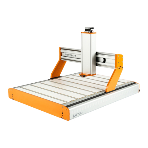
STEPCRAFT M Series User manual

1
Operating Manual
Translation of the original
operating manual
Date of: 06-22-2020
CNC System
STEPCRAFT M-Series
Call for consumer information
Customers from outside the U.S.
STEPCRAFT GmbH & Co. KG
An der Beile 2
58708 Menden
Germany
Phone: +49 (0) 2373-179 11 60
E-mail: info@stepcraft-systems.com
Customers from the U.S. / Canada
STEPCRAFT Inc.
59 Field Street, Rear Building
Torrington, CT, 06790
United States
Phone: 001-203-5561856
E-mail: info@stepcraft.us

NOTICE
All instructions, warranties and other collateral documents are subject to change at the sole discretion of
STEPCRAFT GmbH & Co. KG. For up-to date product literature, visit www.stepcraft.us for customers from North
America and Mexico or www.stepcraft-systems.com for customers from the rest of the world and click on the ser-
vice tab for this product.
Meaning of Special Language
The following terms are used throughout the product literature to indicate various levels of potential harm when
operating this product: The purpose of safety symbols is to attract your attention to possible dangers. The safety
symbols, and their explanations, deserve your careful attention and understanding. The safety warnings them-
selves do not eliminate any danger. The instructions or warnings they give are not substitutes for proper accident
prevention measures.
NOTICE
Procedures which, if not properly followed, create a possibility of physical property damage AND
a little or no possibility of injury.
CAUTION
Procedures which, if not properly followed, create a probability of physical property damage
AND a possibility of serious injury.
WARNING
Procedures which, if not properly followed, create a probability of property damage, collateral
damage, serious injury or death OR create a high probability of superficial injury.
Safety Alert: Indicates caution or warning. Attention is required to avoid serious personal injury.
Read the ENTIRE instruction manual to become familiar with the features of the product and
how to operate them. Failure to operate the product correctly can result in damage to the prod-
uct, personal property and cause serious injury, electric shock and/or fire.
SAVE ALL WARNINGS AND INSTRUCTIONS FOR FUTURE REFERENCE.

3
CONTENT
1. General Instructions ........................................................................................................6
2. Safety Instructions and Protective Measures...................................................................6
General Safety Warnings for the Use of Power Tools...............................................6
Additional Safety Instructions ...........................................................................8
Protective Measures.................................................................................................8
Personal Protective Equipment ................................................................................8
Emergency Stop Switch ...........................................................................................9
Residual Risk ...........................................................................................................9
Safety Symbols ........................................................................................................9
3. Designation and Dimensions of the Machines ...............................................................10
4. Description ....................................................................................................................10
Machine .................................................................................................................10
Workplace ..............................................................................................................10
Intended Use of the Machine..................................................................................11
5. Drawings .......................................................................................................................12
Machine .................................................................................................................12
Control ...................................................................................................................12
Installation Motor Driver Board 4th axis (optional) ............................................13
Installation and Operation of the internal D-Series WinPC-NC module
(optional item no. 12088 required)...................................................................13
6. Assembly, Setup and Installation of the System ............................................................15
Environmental Conditions ......................................................................................15
Positioning the Machine .........................................................................................15
Layout Recommendation .......................................................................................16
Electrical Connection of the Machine .....................................................................17
Tools and Accessories ...........................................................................................17
7. Operation ......................................................................................................................19
Commissioning and safe Operation........................................................................19
Mechanical Axes Limitation .............................................................................20
Emergency Stop..............................................................................................20
Semi Closed Loop SystemTM (optional) ...........................................................20
Blockages due to Accidents or Malfunctions ...................................................20

4
Machine Table........................................................................................................20
MDF Machine Table with Aluminum T-slots ....................................................20
Aluminum T-Slot Table (optional) ....................................................................21
90° T-Slot Table (optional) ..............................................................................21
Arbitrary Combination of the different machine table solutions ........................21
Freestyle MillingTM ...........................................................................................21
Clamping the Workpiece ........................................................................................21
System-guided Tools..............................................................................................22
Operation of the CNC System ................................................................................22
8. Technical Data ..............................................................................................................22
Dimensions and Weight .........................................................................................22
Other Specifications ...............................................................................................23
Pin Assignment Mainboard / Optional Modules ......................................................23
Connector Parallel Port ...................................................................................23
Connector External Signals / Sub-D 15 ...........................................................24
Connector 4th Axis / Sub-D 9 ..........................................................................24
9. Transportation and Storage...........................................................................................24
Transport................................................................................................................24
Packaging ..............................................................................................................25
Storage ..................................................................................................................25
10. Maintenance..................................................................................................................25
General ..................................................................................................................25
Information on Lubrication of igus® dryspin Threaded Lead Screws ................25
Information on Lubrication of optional HIWIN®Ball Screws .............................25
Bosch Rexroth Ball Bearing Guide ..................................................................26
Recommended Maintenance Works.......................................................................26
X-Axis .............................................................................................................26
Y-Axis .............................................................................................................26
Z-Axis..............................................................................................................26
Control Housing ..............................................................................................26
11. Spare Parts ...................................................................................................................27
12. Acoustical noise emissions of the machine ...................................................................27
13. Contact..........................................................................................................................27

6
1. General Instructions
These operating instructions explain the STEPCRAFT M-Series and inform you about the correct han-
dling of the CNC system.
Please read these operating instructions as well as all accompanying documents in their entirety be-
fore commissioning of the system in order to become familiar with the characteristics and the opera-
tion of the product. The improper operation of the CNC gantry milling system can lead to damage to
the product and property and can cause serious injuries, electric shock and / or fire.
It is imperative to adhere to the safety instructions listed in these operating instructions at all times.
Should any doubts or the need for further information arise, do not hesitate to contact us prior to the
commissioning of the CNC system.
2. Safety Instructions and Protective Measures
General Safety Warnings for the Use of Power Tools
Work Area Safety
NOTICE
Keep work area clean and well lit. Cluttered or dark areas invite accidents.
Do not operate the power tool in explosive atmospheres, such as in the presence of flamma-
ble liquids, gases or dust. Power tools create sparks which may ignite the dust or fumes.
NOTICE
Keep children and bystanders at a distance while operating a power tool. Distractions can
cause you to lose control and can result in accidents.
Operate the power tool only in interior spaces on a solid, horizontal table or workbench.
Electrical Safety
Power tool plugs must match the outlet. Never modify the plug in any way. Do not use any
adapter plugs with grounded power tools. Unmodified plugs and matching outlets will reduce the
risk of electric defects and malfunctions.
Do not expose power tools to moisture. The power tool is only suitable for indoor use. Water en-
tering a laser tool will increase the risk of electric shocks.
Personal Safety
Stay alert, watch what you are doing and use common sense when operating a power tool.
Do not use a power tool while you are tired and/or under the influence of drugs, alcohol or
medication. A moment of inattention while operating a power tool may result in serious personal in-
jury.
NOTICE
All persons who operate the power tool must have read and fully understood all relevant
safety and operating instructions. Misunderstanding may result in personal injury.
Use personal protective equipment. Always wear eye protection. Protective equipment, such as
a suitable dust mask or ear protection, reduces the risk of injuries.
NOTICE
Dress properly. Do not wear loose clothing or jewelry. Pin your hair above your shoulders so
that it cannot get caught in the linear guides or moving parts.
This tool is controlled by a computer. During operation, it cannot be controlled directly. Lack of
caution or expertise as well as program errors can lead to unexpected movements.
Do not touch the insertion tools or motors as they can heat up significantly during operation.
Never place any parts of the tool or accessories in the mouth as this can lead to serious inju-
ries.

7
Use of the Power Tool
Do not alter or misuse the tool. Any alteration or modification is a misuse and may result in seri-
ous personal injury.
Disconnect the plug from the power source before you make any adjustments, change acces-
sories, or store the tool. Such preventive safety measures reduce the risk of starting the power tool
accidentally.
Store idle power tools out of the reach of children and do not allow persons unfamiliar with
the laser tool or these instructions to operate the power tool. Power tools are dangerous in the
hands of untrained users.
NOTICE
Use the power tools, accessories etc. in accordance with these instructions, taking into ac-
count the working conditions and the work to be performed. Use of the power tool for opera-
tions different from those intended could result in a hazardous situation with high probability of su-
perficial injury.
NOTICE
Do not reach in the area of the rotating insertion tools. The proximity of the rotating tools to your
hand may not always be obvious.
NOTICE
Never use dull or damaged insertion tools. Sharp bits must be handled with care. Damaged
bits can snap during use. Dull bits require more force to cut the tool, possibly causing the bit to
break.
NOTICE
The speed and feed of the bit when carving, routing or cutting is very important. Always ob-
serve the speed and feed for the particular bit recommended.
If the workpiece or bit becomes jammed or bogged down, turn the power tool "OFF" by the
switch. Wait for all moving parts to stop and unplug the tool, then free the jammed material. If
the switch to the tool is left "ON", the tool could restart unexpectedly causing serious personal injury.
NOTICE
Do not leave a running tool unattended, turn power off. Only when tool comes to a complete
stop and is disconnected from the mains it is safe.
NOTICE
Do not touch the bit or collet after use. After usage bit and collet are too hot to be touched with
bare hands.
NOTICE
Clean the tool's air vents every four hours by using compressed air. Excessive accumulation of
powdered metal inside the motor housing may cause electrical failures.
NOTICE
Do not allow familiarity gained from frequent use of your rotary tool to become common-
place. Always remember that a careless fraction of a second is sufficient to inflict severe injury.
When using the end mills, V-bits or cutters, always have the workpiece securely clamped.
Never attempt to hold the workpiece with your hands while using any accessories. These
tools can jam easily in the material, and can kickback, causing loss of control resulting in serious in-
jury.
Care of the Power Tools
NOTICE
Maintain the tools. Check for misalignment or binding of moving parts, breakage of parts and
any other conditions that may affect the power tool's operation. If damaged, have the power
tool repaired before use. Many accidents are caused by poorly maintained power tools.
NOTICE
Have your power tool serviced by a qualified repair person using only identical replacement
parts. This will ensure that the safety of the laser tool is maintained.

8
Additional Safety Instructions
Depending on the application field of the machine (private or commercial), observe the appli-
cable occupational safety and health, safety and accident prevention and environmental reg-
ulations.
Some dust created by cutting, milling or other construction activities contains chemicals
known to cause cancer, birth defects or other reproductive harm. Some examples of these
chemicals are: Lead from nonferrous metals with lead content, carbonate from carbon fiber,
arsenic and chromium from chemically treated lumber.
Your risk from exposures to these varies, depending on how often you perform this type of work. To
reduce your exposure to these chemicals: work in a well ventilated area, and work with approved
safety equipment, such as those dust masks that are specially designed to filter out microscopic par-
ticles.
Protective Measures
The M-Series has been constructed for advanced users and is only to be operated by technically
skilled persons above the age of 16.
The CNC gantry milling system as well as associated tools, small parts and electrical components are
to be stored outside the reach of children. The operator is solely responsible for understanding and
reading the machine user guide and all relevant operating instructions in their entirety as well as for
the storage of these documents in immediate vicinity of the machine.
The manufacturer`s instructions concerning the CNC machine and the tools, such as the milling spin-
dle, are to be adhered to.
The CNC gantry milling system is only to be used in a technically perfect condition which is to be en-
sured prior to each operation.
The emergency switch as well as, if applicable, additional safety devices, always need to be easily ac-
cessible and fully functional.
The use of liquids with the machine, such as the application of a coolant pump, is prohibited as it can
damage the electronics.
The use of lubrication systems is allowed. Please take into consideration that in this case the MDF
machine table is not used as its MDF panels can swell and, thus, be destroyed.
Personal Protective Equipment
When working with the CNC gantry system, the operator has to wear at least the following personal
protective equipment and has to be compliant with the below-mentioned safety aspects:
- Safety googles for protecting the eyes against flying chips etc.
- Ear protection for protecting the ears against sound and noise.
- No wearing of clothes which can get caught in the machine, such as ties, scarfs, wide sleeves
etc. Additionally, jewelry and especially long necklaces and rings are to be dispensed with.
- Shoulder-length or longer hair is to be secured with a hairnet or a hat to prevent it from getting
caught in the linear guides and / or rotating tools.
Prior to all adjustments to the machine, its control or system-guided tools, such as the milling motor,
the Drag Knife or the Hot Wire Cutter, the plug is to be disconnected from the power source.
Never hold the workpiece to be processed with your hands. It is mandatory that the workpiece is se-
curely fixed on the machine table. Otherwise there exists a high risk of injuries!

9
Emergency Stop Switch
The emergency stop is located in a separate housing with a magnetic disk and is firmly connected with
the machine. In order to be able to intervene at all times, the emergency stop has to be positioned at a
suitable place.
By pressing the emergency stop switch, the emergency stop is triggered. The control is interrupted.
Additionally, the control software receives the signal to stop the operating process. The machine stops
immediately.
ATTENTION! The emergency stop switch can only effect the stop of all components if these compo-
nents are electronically connected with the emergency stop switch.
If you want to use a system-guided tool, such as a milling and drilling motor, that features a separate
ON / OFF switch and that is NOT controlled via the PC, you have to make sure that it is expertly con-
nected with the emergency stop switch, for example by use of the Switch Unit SE2300 for electric con-
sumers (Item no. 10052). If you do not comply with these requirements, the system-guided tool will
continue to run although you have activated the emergency stop switch leading to a high risk of per-
sonal injury and damage to property!
If you have any questions, please do not hesitate to contact us!
Residual Risk
Despite all safety precautions against the contact with rotating or hot tools and the protection from
crushes, a residual risk remains due to a careless handling and automatic movements of the CNC
system.
Safety Symbols
Symbol
Name
Explanation
Symbol: Read manual Alerts user to read manual BEFORE first commissioning
Symbol: Wear ear protection Alerts user to wear a hearing protector
Symbol: Wear safety glasses Alerts user to wear protective glasses
Grounding symbol Alerts user to ground the laser tool / electrical system
General warning symbol Alerts user to warning messages

10
3. Designation and Dimensions of the Machines
The STEPCRAFT M-Series is a CNC gantry milling system and available in the sizes M.500, M.700
und M.1000.
Machine TypeDimensions Working Space Weight
STEPCRAFT M.500
L 726 x W 583 x H 646* mm
543 x 348 x 194 mm
28 kg
STEPCRAFT M.700
L 926 x W 713 x H 646* mm
743 x 479 x 194 mm
35 kg
STEPCRAFT M.1000
L 1226 x W 913 x H 646* mm
1044 x 679 x 194 mm
42 kg
* Machine height with extended Z-axis.
4. Description
Machine
The STEPCRAFT M-Series is a multifunctional CNC gantry milling system for the permanent and reg-
ular processing of wood, plastics and non-ferrous metals. The construction is based on aluminum ex-
trusions specifically designed by STEPCRAFT which have a variety of functions such as guidance and
dust protection. Due to their special design the aluminum extrusions ensure a high stability and ten-
sional stiffness.
The machine has three axes which are offset by 90°. This way, it is possible to travel to any point
within the working space. Each axis is equipped with up to two stepper motors and reference
switches. The stepper motors drive the movable axes elements via the threaded spindle. The position
of the axis is determined during the reference run, at the beginning of the job, with the aid of the refer-
ence switch.
The machine table consists out of white coated MDF panels with aluminum T-slots for the variable fix-
ture of workpieces and accessories.
The STEPCRAFT CNC gantry milling system consists out of the following, sometimes optional, com-
ponents:
- CNC gantry milling system M.500, M.700 or M.1000;
- electronic control unit in a separate sheet housing attached to the rear side of the CNC system
with internal parallel module and connected USB or network module;
- system-guided tools such as a milling motor;
- PC incl. control software with clock/direction output signals such as WinPC-NC or UCCNC.
Workplace
The workplace needs to provide enough space around the CNC gantry milling system for the machine
to work comfortably and to be able to fully use its traveling paths. Additionally, a safe distance to pos-
sibly nearby positioned machines is to be maintained.
The location of the machine as well as the workplace surrounding the machine has to be sufficiently
illuminated.
The PC controlling the machine is to be placed in the vicinity of the machine in order to have both in
clear view.

11
Intended Use of the Machine
The STEPCRAFT M-Series is constructed for a permanent and regular application in the industrial
sector. Due to the torsional stiffness, a variety of different materials, such as wood and non-ferrous
metals, can be processed.
The following manufacturing processes and application are possible:
- machining manufacturing processes such as drilling, plotting / vinyl cutting, engraving and
scratching;
- additive processes, such as 3D printing;
- all processes requiring 3D positioning such as measuring or dosing.

12
5. Drawings
Machine
1) Machine Table
2) Gantry
3) X-axis
4) Y-axis
5) Z-axis
1) Flexi GuidesTM
2) Control electronics
3) Connection side
4) Vision panel status display UCCNC
and D-Series WinPC-NC module
Control
1) Passage air hose for ATC (optional)
2) Passage vacuum hose
3) Status display WinPC-NC module
4) Grounding cable
5) USB cable
6) Connection emergency switch
7) Connection external signals (see chapter 8.3.2)
8) Jack socket 1 (for example for connection tool length sensor or 3D touch probe)
9) Jack socket 2 (see 8)
10) Status displays control (see chapter 6.4)
11) Power supply connection
12) Connection 4th axis (only usable together with the optional motor driver board 4th axis)
1
3
5
2
4
4
3
1
2
3
4
5
6
7
8
9
10
11
12
1
2

13
Installation Motor Driver Board 4th axis (optional)
Remove the control cover (part no. 10)
and put it aside.
Insert the driver board into the designated
slot.
Afterwards, reinstall the control cover.
The 4th axis can now be operated on the
respective slot. Please take into consider-
ation that you may adjust your machine
profile.
Installation and Operation of the internal D-Series WinPC-
NC module (optional item no. 12088 required)
Remove the screw at the spot illustrated in the
picture and replace it with the distance bolt M3 I-
A x 18.
Connect the 26-pin flat ribbon cable with the
socket on the mainboard.

14
Place the internal D-Series WinPC-NC module,
as illustrated in the picture, and reinstall the
screw removed in step 1.
Connect the free end of the 26-pin flat ribbon ca-
ble with the connector on the WinPC-NC mod-
ule.
Connect the USB cable with the module and
guide it through the guide noses in the control
box towards the outside.
The status displays of the internal D-Series
WinPC-NC module can be seen through the vi-
sion panel in the control cover.

15
6. Assembly, Setup and Installation of the System
Environmental Conditions
The machine is solely suitable for the operation in dry, interior spaces.
Keep the environmental temperature of the machine dust-free. High dust exposure can cause dam-
ages to the system.
The humidity should be within normal limits for humidity indoors (40 to 60 %). Protect the machine
against wetness and humidity.
The ideal environmental temperature for the system lies between 18°C to 25°C, respectively from
64°F to 77°F.
Particularly protect the electronics against overheating by avoiding direct sun radiation or indirect heat-
ing up nearby a radiator.
Positioning the Machine
Place the machine on a suitable table or on a machine stand. To provide a comfortable working
height, we recommend a working height of approx. 840 mm. For a torsion-free stand, the surface of
the machine stand needs to be solid and even. The machine is to be secured in a way that it cannot
shift or fall down.
All movable parts of the machine must be able to operate collision-free.
The routing of the tool´s cables, such as with the milling motor, has to be effected in a way that the ca-
ble cannot be clamped between the guide ways of the machine. For this purpose, use the special Flexi
Guides™ on the top of the X-axis.
The machine has to easily accessible and operable. Especially the emergency switch has to be easily
accessible at all times.
Take care to ensure a sufficient illumination of the machine`s location and the workplace surrounding
the machine.
The PC controlling the machine has to be placed in the vicinity of the machine to have both in clear
view.

16
Layout Recommendation
Recommended work area:
•Material feed area: 1m
•Maintenance / Set-up area: 0,5m
•Operating area
Connection on the rear side of the machine:
•Machine control 24 - 30V 180 W
Make sure that no chips can entry via the air inlets of the control attached to the rear side of
the system, for example by bouncing off a wall!
Length (A)
Width (B)
Height (C)
M.500
726 mm
583 mm
646 mm
M.700
926 mm
713 mm
646 mm
M.1000
1226 mm
913 mm
646 mm

17
Electrical Connection of the Machine
If you have purchased the machine as construction kit, the stepper motors as well as the reference
switch and the emergency stop switch have to be connected according to the assembly manual.
Connect the power supply with its low-voltage plug to the power connector socket at the rear side of
the machine. Due to reasons of reverse polarity protection, you have to connect the adapter plug with
the machine before connecting the power supply with the power socket as the machine has no sepa-
rate main switch. Make absolutely sure that the adapter plug is correctly aligned: The notch and the
flattened insulation have to be inserted facing upwards.
The computer has to be connected to the CNC system via parallel port, USB or network interface.
Please take the details regarding the respective connection from the control software you have
bought.
The LED lights of the control board (see chapter 5.2, position 10) are visible from outside. They flash
in case of:
Signal
Explanation
LED2 red
System ok / Power amplifier switched on/ emergency-stop switched
off
LED6 yellow
Power on / 5V
Tools and Accessories
The machine features a 43 mm tool holder that can hold a variety of different tools. In addition to that,
the machine is extendable with supplementary system accessories.
Follow strictly the separate operating manuals of the used tools and accessories!
Below you will find a selection of available tools and system accessories for your CNC machine.
Please see our website (www.shop.stepcraft-systems.com) for our complete range of products.
Item
Item number
Picture
Milling Motor MM-800 11583
Milling Motor MM-1000 10022

18
Milling Motor MM-1000 DI 11789
Milling Spindle HF-500 10016
Automatic Tool Changer 10011 for HF-500
10012 for MM-800/ MM-1000
3D Print Head PH-40 10973
Engraving Laser DL445 10018
Oscillating Tangential
KnifeOTK-3 11024
Aluminum T-slot table
12005 M.500
12006 M.700
12007 M.1000

19
Item
Item number
Picture
T-slot table 90°
11987 M.500
11988 M.700
11989 M.1000
Clamping Set M6 10063
Switch-Box 10101
Switch Unit SE 2300 for exter-
nal consumers 10052
Tool Length Sensor TS-32 10103
7. Operation
Commissioning and safe Operation
The machine and all connected components have to be wired correctly and be in perfect condition.
The operator must have completely read and understood the entire documentation of the M-Series
and corresponding instructions. Furthermore, he must have been trained in operating the machine as
well as its accessories and has to be familiar with the use of CNC gantry milling systems and CNC
software.
The workplace needs to be compliant with the applicable regulations and provisions of the respective
industry.

20
Mechanical Axes Limitation
All axes feature mechanical end stop according to EN 319/ ISO 13854 “Safety of machinery - Mini-
mum gaps to avoid crushing of parts of the human body“, in order to avoid crushes.
Emergency Stop
The emergency stop is located in a separate housing with a magnetic disk and is firmly connected with
the machine. In order to be able to intervene at all times, the emergency stop has to be positioned at a
suitable place.
By pressing the emergency stop switch, the emergency stop is triggered. The machine stops immedi-
ately (see chapter 2.4) which can lead to step and data losses. A controlled stop of the machine can
only be effected via the control software.
Only activate the emergency stop in case of emergency!
If you want to deactivate the emergency stop status, reactivate the control by turning the emergency
stop switch to the right. The operating process has to be restarted.
Semi Closed Loop SystemTM (optional)
The optionally available Semi Closed Loop SystemTM upgrades your CNC system with an electronical
monitoring of all stepper motors regarding possible step losses. If the Semi Closed Loop-SystemTM de-
tects a deviation from the preplanned steps of the respective stepper motor, as in case of a collision or
false settings, the emergency stop is automatically triggered and, thus, your workpiece protected from
potential damage. You now have to identify and eliminate the cause of the step losses, for example a
collision, too high a feed or a mechanical defect of the machine.
Press the emergency stop again to deactivate the emergency stop status.
After homing, the interrupted operation can be continued.
Blockages due to Accidents or Malfunctions
In case of an emergency stop all axis turn currentless and can only be moved manually with increased
effort.
Machine Table
The machine table of the STEPCRAFT M-Series can be individually adjusted according to your needs
and projects. For this purpose, the following machine table solutions are available.
MDF Machine Table with Aluminum T-slots
The MDF machine table with aluminum T-slots consists of individual MDF panels of 19 mm strength
and aluminum T-slot profiles M6. The T-slots have a distance of 100 mm to each other and run in X
direction.
The MDF machine table with aluminum T-slots can be inserted in the upper as well as in the lower
guide slot of the Y-axis and, thus, allows a change of the passage height from 135 mm to 195 mm.
Other manuals for M Series
6
This manual suits for next models
3
Table of contents
Other STEPCRAFT Control System manuals
Popular Control System manuals by other brands

Bryant
Bryant ZONE PERFECT PLUS ZONEBB2KIT installation instructions

Helm
Helm Trend Series operating instructions

Quick
Quick 8802 Operation manual

Johnson Controls
Johnson Controls CMS-1655 installation guide

Dakota Digital
Dakota Digital CRC-1000 quick start guide

DoorKing
DoorKing 2112 Installation & owner's manual