Konica Minolta PF-122 User manual

PF-122
Service Manual
19971
Cover(op).fm Page 1 Friday, August 29, 2003 10:25 AM


i
CONTENTS
GENERAL
1. Specifications ...................................................................................................G-1
2. Revolving Parts Layout Drawing ......................................................................G-1
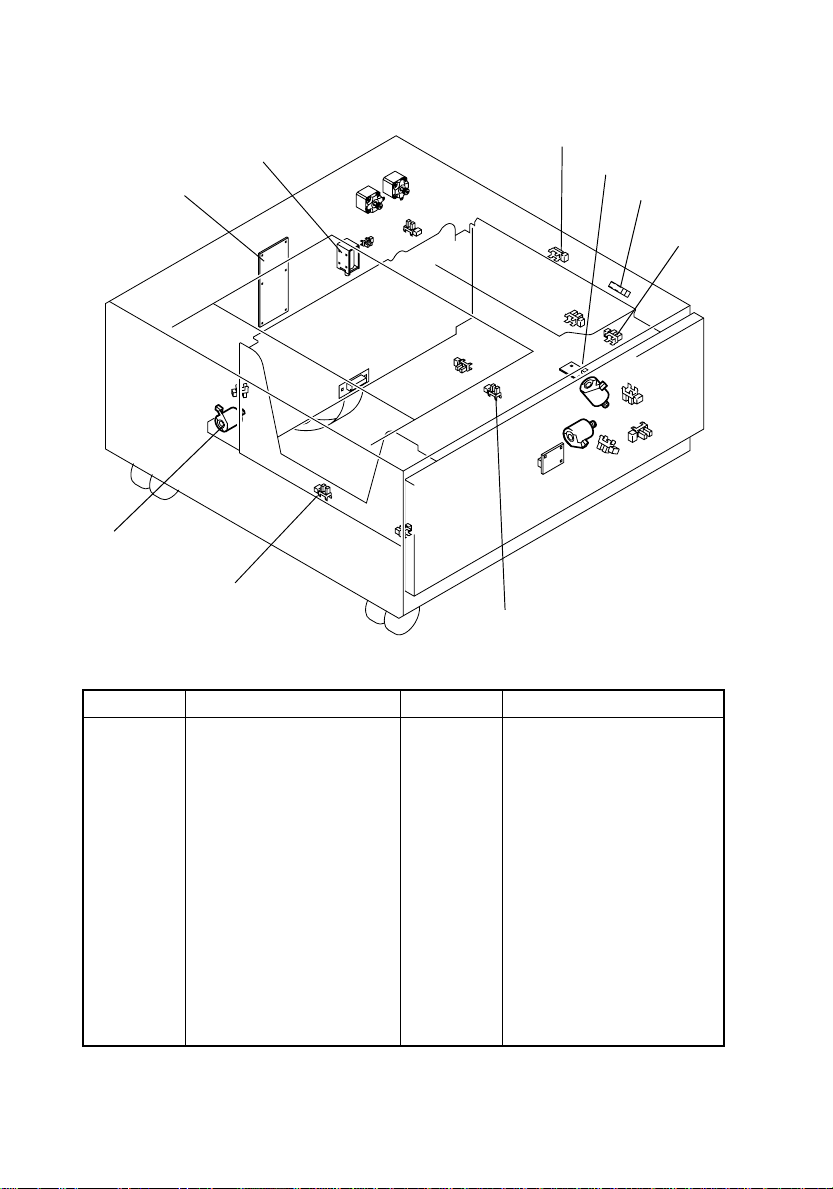
3. Electric Parts Layout Drawing ..........................................................................G-2
DIS/REASSEMBLY, ADJUSTMENT
1. Maintenance Schedule .....................................................................................D-1
2. Disassembly and Cleaning ...............................................................................D-2
2-1. Removal of the Outer Cover ....................................................................D-2
2-2. Removal of the Drawer ............................................................................D-3
2-3. Removal of the Wire .................................................................................D-3
2-4. Removal of the Pickup Roller/Take-Up Roller/Separator Roll Assy .........D-6
2-5. Cleaning of the Pickup Roller/Paper Take-Up Roller/Separator Roll .......D-9
2-6. Cleaning of the Vertical Transport Roller .................................................D-9
3. Adjustment .......................................................................................................D-10
3-1. Registration CD ........................................................................................D-10
3-2. Registration FD ........................................................................................D-13
3-3. Shifter Movement Timing Belt Adjustment ...............................................D-15
TROUBLESHOOTING
1. Introduction ......................................................................................................T-1
1-1. Electrical Components Check Procedure ................................................T-1
(1) Sensor .............................................................................................T-1
(2) Switch .............................................................................................T-2
(3) Solenoid ...........................................................................................T-2
(4) Clutch .............................................................................................T-3
(5) Motor .............................................................................................T-3
2. I/O CHECK .......................................................................................................T-5
2-1. I/O Check List ...........................................................................................T-6
3. Misfeed Detection/Troubleshooting Procedures ..............................................T-7
3-1. Initial Checks ............................................................................................T-7
3-2. Misfeed-Detecting Sensor Layout ............................................................T-8
3-3. Misfeed Detected .....................................................................................T-9
3-4. Misfeed Detection Timing/Troubleshooting Procedures ..........................T-10
(1) LCC Paper Take-Up Misfeed ...........................................................T-10
4. Malfunction Detection/Troubleshooting Procedure ..........................................T-11
4-1. Malfunction Detection ...............................................................................T-11
5. Malfunction Detection Timing and Troubleshooting Procedure .......................T-13
(1) C0B56: LCC Elevator Motor Failure ................................................T-13
(2) C0991: LCC Lift Failure ...................................................................T-14
(3) C0996: LCC Lock Release Failure ..................................................T-15
(4) C0997: LCC Shift Gate Operation Failure .......................................T-16
(5) C0998: LCC Shift Failure .................................................................T-17
(6) C0998: LCC Shift Motor Failure .......................................................T-18
(7) C099D: LCC Communication Failure ...............................................T-18
PF-122TOC.fm Page i Friday, August 29, 2003 10:26 AM


GENERAL
Cover_G.fm Page 1 Friday, August 29, 2003 10:26 AM


G-1
1. Specifications
2. Revolving Parts Layout Drawing
Name : Large Capacity Cabinet
Type : Front loading type LCC
Installation : Desk type
Paper Type : Plain paper 15lb. to 24lb. (56 g/m2to 90 g/m2),
recycled paper 16lb. to 24lb. (60 g/m2to 90 g/m2)
Paper Size : A4C, Letter C
Capacity : 2750 sheets 21.3lb. (80 g/m2)
Document Alignment : Center baseline
Power Requirements : DC 24 V ± 10 % (supplied from the copier)
DC 5 V ± 5 %
Max. Power Consumption : 45 W or less
Dimensions : 570(W) x 263(H) x 564(D) mm
22-1/2 x 10-1/4 x 22-1/4
Weight : Approx. 26 kg (53-1/4 lbs)
Operating Environment : Conforms to the operating environment of the copier.
4348M001AB
Shift Gate Drive
Paper Take-Up/Transport Revolving Section
Main Tray
Paper Lift-Up Drive
Shifter Drive
G.fm Page 1 Friday, August 29, 2003 10:27 AM

G-2
3. Electric Parts Layout Drawing
Symbol Name Symbol Name
PWB-C1
LCC
PWB-E LCC
PWB-H LCC
UN1-LCC
M1-LCC
M2-LCC
M3-LCC
M4-LCC
M5-LCC
SL1-LCC
PC1-LCC
PC2-LCC
PC3-LCC
Control Board
Paper Empty Board
Connector Interface Board
Paper Descent Key
LCC Take-Up Motor
Vertical Transport Drive
Motor
Shift Gate Motor
Shift Motor
Elevator Motor
Tray Lock Solenoid
LCC Paper Take-Up Sensor
LCC Vertical Transport Sen-
sor
Upper Paper
Empty Sensor
PC4-LCC
PC5-LCC
PC6-LCC
PC7-LCC
PC8-LCC
PC9-LCC
PC10-LCC
PC11-LCC
PC12-LCC
PC13-LCC
PC14-LCC
Tray Upper Limit Sensor
Right Lower Door Sensor
Tray Set Sensor
Lower Limit Sensor
Shift Motor Pulse Sensor
Shift Tray Paper
Empty Sensor
Elevator Motor
Pulse Sensor
Shifter Stop Position Sensor
Shifter Home Position Sensor
Elevator Lower Position Sen-
sor
Shift Gate Home Position
Sensor
4348M003AA
PWB-H LCC
PWB-C1 LCC
SL1-LCC
PC6-LCC
PC5-LCC
M2-LCC
M1-LCC
PC4-LCC
PC14-LCC
M3-LCC
PC12-LCC
PC9-LCC
UN1-LCC
PC10-LCC
PC8-LCC
M5-LCC
PWB-E LCC
M4-LCC
PC7-LCC
PC13-LCC
PC11-LCC
PC2-LCC
PC1-LCC
PC3-LCC
G.fm Page 2 Friday, August 29, 2003 10:27 AM

DIS/REASSEMBLY,
ADJUSTMENT
Cover_D.fm Page 1 Friday, August 29, 2003 10:28 AM


D-1
1. Maintenance Schedule
• To ensure that the copier produces good copies and to extend its service life, it is recom-
mended that the maintenance jobs described in this schedule be carried out as
instructed.
NOTES
•K = 1,000 copies
•Replace the Paper Take-Up Roller and Separator Roll at the same time.
•
❍
indicates cleaning when transport failure occurs.
•The contents of this maintenance schedule are subject to change without notice.
•For part numbers, see Parts Manual and Parts Modification Notice.
PM Parts
Job
Item Used for Cleaning Qty Ref. Page
Clean Repla
ce
Pickup Roller ❍300K
Alcohol and soft cloth
1☞ D-6,9
Paper Take-Up Roll ❍300K 1 ☞ D-6,9
Separator Roll Assy ❍300K 1 ☞ D-6,9
Vertical Transport
Roller ❍—1☞ D-9
D.fm Page 1 Friday, August 29, 2003 10:44 AM

D-2
2. Disassembly and Cleaning
2-1. Removal of the Outer Cover
No. Name Removal Procedure
1 Front Right Cover Remove two screws and the drawer.
2 Rear Right Cover Remove two screws and the drawer.
3 Right Door Open the Right Door. →Remove the Right Door.
4 Lower Right Cover Remove two screws and the drawer.
5 Left Cover Remove four screws and the cover.
6 Rear Cover Remove four screws and the cover.
4348D001AA
4348D002AB
1
2
3
4
5
6
D.fm Page 2 Friday, August 29, 2003 10:44 AM

D-3
2-2. Removal of the Drawer
2-3. Removal of the Wire
1. Press the Drawer Eject Button and slide out the
drawer.
2. Remove the paper.
3. Remove four screws and slide out the drawer.
4348D503AA
4. Remove the connector.
5. Remove two screws and the Connector Board.
6. Remove the Drawer.
NOTE
•When removing the Connector Board, use care not
to drop the drawer from the guide rail.
4425D115AA
NOTE
•To prevent injuries, press the guide rail inside the
machine.
4348D505AA
1. Remove the Drawer.
2. Remove four screws and the Front Cover Assy.
3. Unplug one connector.
4348D504AA
4. Remove two screws and the Inner Cover Assy.
4348D506AA
D.fm Page 3 Friday, August 29, 2003 10:44 AM

D-4
5. Remove two screws and the Driver Cover.
4348D507AA
6. Remove three screws and the Driver Mounting
Plate Assy.
4348D508AA
NOTE
•When reinstalling, use caution in the engagement
of the gears.
1161D017AA
7. Remove three screws and the Reinforcement
Bracket Assy.
4348D509AA
8. Remove four Pulley Covers.
9. Unhook four pulleys.
4348D510AA
D.fm Page 4 Friday, August 29, 2003 10:44 AM

D-5
10. Remove one Ground Plate.
11. Remove four Cable Holding Jigs and the Main
Drawer.
NOTE
•Use care not to bend the wires.
4348D511AA
12. Remove four screws and the Rear Trailing Edge
Assy.
4348D512AA
13. Remove four screws and the Front Trailing Edge
Assy.
4348D513AA
14. Remove three C-rings, two bushings, and two
gears.
15. Remove the Take-Up Drum Assy.
4348D514AA
16. Remove two C-rings, two fixing pins, and the
Take-Up Drum Assy.
NOTE
•When reinstalling the Take-Up Drum, check that
the direction of the wire coming from both Take-Up
Drums are the same.
4425D114AA
D.fm Page 5 Friday, August 29, 2003 10:44 AM

D-6
2-4. Removal of the Pickup Roller/Take-Up Roller/Separator Roll
Assy
1. Remove the Rear Right Cover.
2. Remove the Right Door.
3. Remove two screws and the Paper Separator
Roll Mounting Bracket Assy.
4348D003AA
4. Remove three C rings and the Paper Separator
Roll Assy.
4030D053AB
5. Remove four screws and the Paper Take-Up Unit.
4348D004AA
6. Remove two screws and the cover.
7. Remove one C-ring and remove the gear.
4348D501AA
D.fm Page 6 Friday, August 29, 2003 10:44 AM

D-7
8. Remove two C-rings and remove the bushing.
9. Remove the Roll Assy.
4030D059AA
10. Remove two C-rings and remove the bushing.
11. Remove the Roll Assy.
4030D046AA
12. Remove one C-clip and remove the Paper Take-
Up Roll.
4030D047AA
13. Remove two C-rings and remove the bushing.
4348D502AA
14. Remove one C-clip and remove the Pickup
Roller.
4030D049AA
D.fm Page 7 Friday, August 29, 2003 10:44 AM

D-8
Precaution for Reinstallation of the Separator Roll Assy
•Install the Separator Roll Assy while pressing the holder down so that it aligns to the
metal bracket of the copier.
4348D517AA
D.fm Page 8 Friday, August 29, 2003 10:44 AM

D-9
2-5. Cleaning of the Pickup Roller/Paper Take-Up Roller/Separa-
tor Roll
1. Remove the Rear Right Cover.
2. Remove the Right Door.
2-6. Cleaning of the Vertical Transport Roller
3. Remove two screws and the Paper Separator
Roll Mounting Bracket Assy.
4348D003AA
4. Using a soft cloth dampened with alcohol, wipe
the Separator Roll clean of dirt.
4348D005AA
5. Using a soft cloth dampened with alcohol, wipe
the Pickup Roller and Paper Take-Up Roller clean
of dirt.
4348D006AA
1. Open the Right Door.
2. Using a soft cloth dampened with alcohol, wipe
the Vertical Transport Roller clean of dirt.
4348D007AB
D.fm Page 9 Friday, August 29, 2003 10:44 AM

D-10
3. Adjustment
3-1. Registration CD
NOTE
Make this adjustment after any of the following procedures has been performed.
•When the PH Unit has been replaced.
•When the image on the copy is offset in the FD direction.
•When a faint image occurs on the leading edge of the image.
1. Display Tech. Rep. Mode.
4344S504CA
2. Press the Stop key followed by the Start key to
display the Adjust Mode.
3. Touch the Printer key.
4348P002CA
4. Touch the Registration (CD) key.
4348P008CA
5. Touch the Test Print key.
4348P014CA
D.fm Page 10 Tuesday, September 2, 2003 8:46 AM
Table of contents
Other Konica Minolta Office Equipment manuals