Konica Minolta DF-619 User manual

SERVICE MANUAL
2010.01
Ver. 1.0
THEORY OF OPERATION
More Service Manuals at www.service-manual.netMore Service Manuals at www.service-manual.netMore Service Manuals at www.service-manual.netMore Service Manuals at www.service-manual.netMore Service Manuals at www.service-manual.net
WWW.SERVICE-MANUAL.NETWWW.SERVICE-MANUAL.NETWWW.SERVICE-MANUAL.NETWWW.SERVICE-MANUAL.NETWWW.SERVICE-MANUAL.NET

Revision history
After publication of this service manual, the parts and mechanism may be subject to change for
improvement of their performance.
Therefore, the descriptions given in this service manual may not coincide with the actual machine.
When any change has been made to the descriptions in the service manual, a revised version will be
issued with a revision mark added as required.
Revision mark:
• To indicate clearly a section revised, is shown at the left margin of the revised section.
The number inside represents the number of times the revision has been made.
• To indicate clearly a page that contains the revision, is shown near the page number of the
corresponding page.
The number inside represents the number of times the revision has been made.
NOTE
Revision marks shown in a page are restricted only to the latest ones with the old ones deleted.
• When a page revised in Ver. 2.0 has been changed in Ver. 3.0:
The revision marks for Ver. 3.0 only are shown with those for Ver. 2.0 deleted.
• When a page revised in Ver. 2.0 has not been changed in Ver. 3.0:
The revision marks for Ver. 2.0 are left as they are.
1
1
1
1
2010/01 1.0 — Issue of the first edition
Date Service manual Ver. Revision mark Descriptions of revision
WWW.SERVICE-MANUAL.NETWWW.SERVICE-MANUAL.NETWWW.SERVICE-MANUAL.NETWWW.SERVICE-MANUAL.NETWWW.SERVICE-MANUAL.NET

DF-619
OUTLINE
CONFIGURATION/
OPERATION
Theory of Operation Ver. 1.0 Jan. 2010
i
CONTENTS
DF-619
OUTLINE
1. PRODUCT SPECIFICATIONS................................................................................ 1
2. SECTION CONFIGURATION.................................................................................. 4
3. PAPER PATH........................................................................................................... 4
CONFIGURATION/OPERATION
4. CONFIGURATION .................................................................................................. 5
5. DRIVE ..................................................................................................................... 6
6. OPERATION ........................................................................................................... 7
6.1 Paper feed section ................................................................................................ 7
6.1.1 Document feed tray ascent/descent control .................................................. 7
6.1.2 Original take-up control................................................................................. 9
6.1.3Original set detection .................................................................................... 9
6.1.4 Original size detection................................................................................. 10
6.2 Registration section ............................................................................................ 11
6.2.1 Registration control ..................................................................................... 11
6.3Read section....................................................................................................... 12
6.3.1 Reading transport control............................................................................ 12
6.3.2 Reading roller pressure/retraction control ................................................... 13
6.3.3DF original glass contamination prevention control .................................... 14
6.3.4 CISoriginal reading control......................................................................... 16
6.3.5 CIScontrol when sub-power switch isturned ON....................................... 18
6.3.6 CIScontrol when the document isloaded .................................................. 18
6.3.7 CIScontrol when the start key ispressed................................................... 19
6.3.8CISglass contamination prevention control ................................................ 21
6.3.9 CISpower control........................................................................................ 22
6.3.10 Guide set detection ..................................................................................... 22
6.4 Paper exit section ............................................................................................... 23
6.5 Paper path .......................................................................................................... 24
6.5.1 1-sided mode .............................................................................................. 24
6.5.2 2-sided mode .............................................................................................. 24
6.6 Open/close detecting section.............................................................................. 26
6.6.1 DF angle open/close detection ................................................................... 26
6.6.2 DF open/close detection ............................................................................. 26
WWW.SERVICE-MANUAL.NETWWW.SERVICE-MANUAL.NETWWW.SERVICE-MANUAL.NETWWW.SERVICE-MANUAL.NETWWW.SERVICE-MANUAL.NET

DF-619
OUTLINE
CONFIGURATION/
OPERATION
Theory of Operation Ver. 1.0 Jan. 2010
ii
6.7 Fan control.......................................................................................................... 27
6.7.1 Function ...................................................................................................... 27
6.7.2 Control conditions....................................................................................... 27
WWW.SERVICE-MANUAL.NETWWW.SERVICE-MANUAL.NETWWW.SERVICE-MANUAL.NETWWW.SERVICE-MANUAL.NETWWW.SERVICE-MANUAL.NET

Theory of Operation Ver. 1.0 Jan. 2010 1. PRODUCT SPECIFICATIONS
1
OUTLINE DF-619
OUTLINE
1. PRODUCT SPECIFICATIONS
A. Type
B. Functions
C. Paper type
*1: For the combined original detection mode, refer to the mixed original feed chart.
Name Reverse automatic document feeder
Ty p e
Paper feed section Paper feed from top of stack
Image reading section Sheet-through system
Back side: Reading by CIS
Exit section Straight exit system
Installation Screw cramp to the main body
Document alignment Center
Document loading Face up
ModesStandard mode / Mixed original detection mode / FAX mode
Type of document
Standard mode
1-sided mode
35 to 210 g/m2(9.25 to 55.75 lb)
2-sided mode
50 to 210 g/m2(13.25 to 55.75 lb)
Mixed original detection mode 1-sided / 2-sided mode
50 to 128g/m2(13.25 to 34 lb)
FAX mode
1-sided mode
35 to 210 g/m2(9.25 to 55.75 lb)
2-Sided Mode
50 to 210 g/m2(13.25 to 55.75 lb)
Detectable document
size*1 Standard mode/FAX mode Metric area: B6Sto A3
Inch area: 5 1/2x 81/2to 11 x 17
Capacity 100 sheets(80 g/m2) or stack of 14 mm and below
WWW.SERVICE-MANUAL.NETWWW.SERVICE-MANUAL.NETWWW.SERVICE-MANUAL.NETWWW.SERVICE-MANUAL.NETWWW.SERVICE-MANUAL.NET

1. PRODUCT SPECIFICATIONSTheory of Operation Ver. 1.0 Jan. 2010
2
OUTLINE DF-619
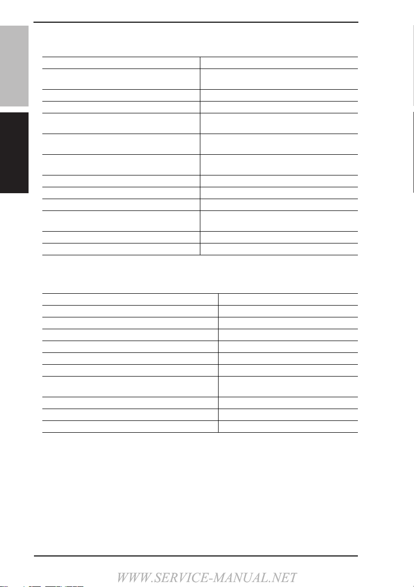
D. Paper feed prohibited originals
• If fed, trouble occurrence will be highly possible.
E. Paper feed not guaranteed originals
• If fed, paper feed will be possible to some extent but trouble occurrence will be possible.
Type of originalPossible trouble
Sheetsstapled or clipped together Paper feed failure, damaged sheet, defective drive
mechanism due to jammed staplesor clips
Sheetsglued together Paper feed failure, damaged sheet
Book originalPaper feed failure, damaged sheet
Original weighing less than 35 g/m2(9.25 lb) or
210 g/m2(55.75 lb) or more Paper feed failure, transport failure
Sheetsfolded, torn or wrinkled Paper feed failure, damaged sheet,
transport failure
Sheetsseverely curled Sheetsmisfed due to being dog-eared or fed in
askew
OHP film (Transparency film) Paper feed failure, transport failure
Label paper Paper feed failure, transport failure
Offset master paper Paper feed failure, transport failure
Glossy photographic paper or glossy enamel
paper Transport failure, damaged sheet
Sheetsclipped or notched Damaged sheet, transport failure
Sheetspatched Patched part folded or torn sheet
Type of originalPossible trouble
Sheetslightly curled (Curled amount: 10 to 15 mm) Dog-eared, exit failure, transport failure
Heat sensitive paper Edge folded, exit failure, transport failure
Ink jet paper Paper feed failure, transport failure
Sheetswith smooth surface (Coated paper) Paper feed failure, transport failure
Intermediate paper Paper feed failure, transport failure
Paper immediately after paper exit from the main unit Paper feed failure, transport failure
Paper with many punched holes(e.g., loose leaf) limited
to vertical feeding Multi-page feed due to flashesfrom holes
Sheetswith 2 to 4 holesTransport failure
Sheetstwo-folded or Z-folded Transport failure, image deformation
Sheetswith rough surface (e.g., letterhead) Paper feed failure
WWW.SERVICE-MANUAL.NETWWW.SERVICE-MANUAL.NETWWW.SERVICE-MANUAL.NETWWW.SERVICE-MANUAL.NETWWW.SERVICE-MANUAL.NET

Theory of Operation Ver. 1.0 Jan. 2010 1. PRODUCT SPECIFICATIONS
3
OUTLINE DF-619
F. Mixed original feed chart
For metric
For inch
G. Machine specifications
H. Operating environment
Conformsto the operating environment of the main body.
NOTE
• These specifications are subject to change without notice.
Max. original
size 297 mm 257 mm 210 mm 182 mm 148mm 128mm
Mixed original size A3A4 B4 B5 A4SA5 B5SA5SB6S
297 mm A3OKOK----- - -
A4 OKOK----- - -
257 mm B4 OK OK OK OK - - - - -
B5 OK OK OK OK - - - - -
210 mm A4SOK OK OK OK OK OK - - -
A5 NG NG OK OK OK OK - - -
182 mm B5SNG NG OK OK OK OK OK - -
148mm A5SNG NG NG NG NG NG NG OK -
128mm B6SNG NG NG NG NG NG NG OK OK
Max. original size 11 81/25 1/2
Mixed original size 11 x 17 81/2x 11 81/2x 14 81/2x 11S5 1/2x 81/25
1/2x 81/2S
11 11 x 17 OK OK - - - -
81/2x 11 OK OK - - - -
81/2
81/2x 14 OK OK OK OK OK -
81/2x 11SOK OK OK OK OK -
5 1/2x 81/2NG NG OK OK OK -
5 1/25 1/2x 81/2SNG NG NG NG NG OK
OK Mixed original feed available (Tilted with in 1.5% or less)
NG No. mixed original feed
-Can not set original
Power requirements
DC 24 V (supplied from the main body)
DC 15 V (CIS: supplied from the main body)
DC 5 V (supplied from the main body)
Max. power
consumption 80 W or less
Dimensions618mm (W) x 576 mm (D) x 130 mm (H)
24.33 inch (W) x 22.68inch (D) x 5.12 inch (H)
Weight 18.0 kg (39.68lb)
WWW.SERVICE-MANUAL.NETWWW.SERVICE-MANUAL.NETWWW.SERVICE-MANUAL.NETWWW.SERVICE-MANUAL.NETWWW.SERVICE-MANUAL.NET

2. SECTION CONFIGURATION Theory of Operation Ver. 1.0 Jan. 2010
4
OUTLINE DF-619
2. SECTION CONFIGURATION
3. PAPER PATH
A108T2C505AA
Paper feed section
Read section
Registration section
Paper exit section
A108T2C506AA
Feed tray
Exit tray
Front side (scanner original read position)
Back side (CISoriginal read position)
WWW.SERVICE-MANUAL.NETWWW.SERVICE-MANUAL.NETWWW.SERVICE-MANUAL.NETWWW.SERVICE-MANUAL.NETWWW.SERVICE-MANUAL.NET

Theory of Operation Ver. 1.0 Jan. 2010 4. CONFIGURATION
5
CONFIGURATION/
OPERATION DF-619
CONFIGURATION/OPERATION
4. CONFIGURATION
A108T2C501AA
A108T2C502AA
A108T2C001DA
Transportation cover Document feed tray
Document guide Original read section
Separation roller
Feed roller
Reading roller 1
Exit roller
Registration roller
Reading roller 2
Pick-up roller
Conveyance roller
Reading roller 3
CISmodule (CIS)
CISpower supply (CISPU)
CISinverter board (CINVB)
DF control board (DFCB)
WWW.SERVICE-MANUAL.NETWWW.SERVICE-MANUAL.NETWWW.SERVICE-MANUAL.NETWWW.SERVICE-MANUAL.NETWWW.SERVICE-MANUAL.NET

5. DRIVE Theory of Operation Ver. 1.0 Jan. 2010
6
DF-619
CONFIGURATION/
OPERATION
5. DRIVE
A108T2C002DA
Take-up motor (M2)
Registration motor (M3)
Exit motor (M4)
Reading motor (M1)
Lift-up motor (M5)
Reading roller pressure/retraction
motor (M6)
Front side cleaning motor (M8)
Take-up clutch (CL1)
Back side cleaning motor (M7)
WWW.SERVICE-MANUAL.NETWWW.SERVICE-MANUAL.NETWWW.SERVICE-MANUAL.NETWWW.SERVICE-MANUAL.NETWWW.SERVICE-MANUAL.NET

Theory of Operation Ver. 1.0 Jan. 2010 6. OPERATION
7
CONFIGURATION/
OPERATION DF-619
6. OPERATION
6.1 Paper feed section
6.1.1 Document feed tray ascent/descent control
• The document feed tray will move up to feed the original.
• The lift-up motor providesthe drive for ascent/descent motion of the document feed tray.
A. Ascent motion
• The document feed tray isstationary at the lower limit position in the standby state.
• The lift-up motor isenergized when the start key ispressed with the original loaded in
position.
• The lift-up motor will rotate the drive cam through the gear. The lift up lever movesalong
the cam, so that the document feed tray movesup to the take-up position.
• The document feed tray will stop moving up when the lift up upper sensor istransmitted.
A108T2C004DA
A108T2C003DA
Lift-up motor (M5)
Empty sensor (PS1)
Lift up lower sensor (PS3)
Lift up upper sensor (PS2)
Drive cam
Ascent position
Descent position
Lift up lever
Lift up upper sensor (PS2)
Lift up lower sensor (PS3)
WWW.SERVICE-MANUAL.NETWWW.SERVICE-MANUAL.NETWWW.SERVICE-MANUAL.NETWWW.SERVICE-MANUAL.NETWWW.SERVICE-MANUAL.NET

6. OPERATION Theory of Operation Ver. 1.0 Jan. 2010
8
DF-619
CONFIGURATION/
OPERATION
B. Descent motion
• When all the originalsare fed and the empty sensor isinterrupted, the lift-up motor will
reverse.
• The lift-up motor will rotate the drive cam through the gear.
The lift up lever movesalong the cam, so that the document feed tray movesdown.
• The document feed tray will stop moving down when the lift up lower sensor isinter-
rupted.
WWW.SERVICE-MANUAL.NETWWW.SERVICE-MANUAL.NETWWW.SERVICE-MANUAL.NETWWW.SERVICE-MANUAL.NETWWW.SERVICE-MANUAL.NET

Theory of Operation Ver. 1.0 Jan. 2010 6. OPERATION
9
CONFIGURATION/
OPERATION DF-619
6.1.2 Original take-up control
• The take-up motor providesthe drive for original take-up operations.
• The drive from the take-up motor istransmitted to the pick-up roller and feed roller when
the take-up clutch isenergized. The original ispicked up and fed in by the rotation of the
rollers.
• The original picked up and fed in istransported onto the conveyance roller that isdriven
by the take-up motor.
6.1.3 Original set detection
• To prevent aoriginal set mistake, the original set sensor detectsaoriginal loaded in the
document feed tray.
A108T2C005DA
Take-up motor (M2)
Separation roller
Feed roller
Pick-up roller
Conveyance roller
Take-up clutch (CL1)
A108T2C006DA
Original set sensor (PS17)
Document feed tray
WWW.SERVICE-MANUAL.NETWWW.SERVICE-MANUAL.NETWWW.SERVICE-MANUAL.NETWWW.SERVICE-MANUAL.NETWWW.SERVICE-MANUAL.NET

6. OPERATION Theory of Operation Ver. 1.0 Jan. 2010
10
DF-619
CONFIGURATION/
OPERATION
6.1.4 Original size detection
• The original size isdetected by the combination of the three length sensorsand one
restriction plate positional volume.
A. Detecting the width of the original 1
• The width of the original will be detected by the restriction plate positional volume under
the document feed tray.
• Moving the document guide will rotate the gear. Then, the detection part of the restriction
plate positional volume mounted coaxially with the gear isrotated. The width of the origi-
nal iscalculated based on the value detected through the rotation of the detection part.
B. Detecting the width of the original 2
• Three consolidation sensorsare mounted to where the paper passesimmediately after it
isfed. It isfor detecting the width of the original for mixed original/AMS.
C. Detecting the length of the original 1
• The length of the original will be detected by the length sensor/1/2/3.
• Length sensor/1 and /3are mounted in thisorder with the length sensor/2 being closest
to the feed roller.
D. Detecting the length of the original 2
• The length of the original in the mixed original/AMSmode iscalculated based on the
period of time during which the before read sensor isblocked.
A108T2C007DA
Length sensor/1 (PS10)
Length sensor/3(PS12)
Length sensor/2 (PS11)
Consolidation sensor/1 (PS13)
Consolidation sensor/3(PS15)
Before read sensor (PS6)
Restriction plate positional
volume (VR1)
Consolidation sensor/2 (PS14)
WWW.SERVICE-MANUAL.NETWWW.SERVICE-MANUAL.NETWWW.SERVICE-MANUAL.NETWWW.SERVICE-MANUAL.NETWWW.SERVICE-MANUAL.NET

Theory of Operation Ver. 1.0 Jan. 2010 6. OPERATION
11
CONFIGURATION/
OPERATION DF-619
6.2 Registration section
6.2.1 Registration control
• The original transported from the paper feed section will be transported to the paper exit
section by the registration roller, the reading roller 1 and 2 and 3.
• The registration roller isdriven by the registration motor.
• While the original isbeing transported, aloop isformed in the original between the con-
veyance roller and registration roller to thereby correct any skew in the original.
• The registration sensor detectstime between two successive originalsand the timing at
which to energize the registration motor iscontrolled.
A108T2C008DA
Take-up motor (M2)
Registration sensor (PS5)
Registration motor (M3)
Loop formed
Original
Conveyance roller
Conveyance roller
Registration roller
Registration sensor (PS5) Registration roller
WWW.SERVICE-MANUAL.NETWWW.SERVICE-MANUAL.NETWWW.SERVICE-MANUAL.NETWWW.SERVICE-MANUAL.NETWWW.SERVICE-MANUAL.NET

6. OPERATION Theory of Operation Ver. 1.0 Jan. 2010
12
DF-619
CONFIGURATION/
OPERATION
6.3 Read section
•A1-sided original isread by the scanner unit section of the main body after the leading
edge of the original has moved past reading roller 1.
For more details, see “8. SCANNER SECTION”.
•A2-sided original isread as follows. The front side of the 2-sided original isread by the
scanner unit section of the main body after the leading edge of the original has moved
past reading roller 1. The back side of the 2-sided original isread by the CISafter the
leading edge of the original has moved past reading roller 2.
6.3.1 Reading transport control
• The reading roller 1 and 2 and 3are driven by the reading motor.
• The 2-sided original (the front side and back side) isread at once in one pass of the orig-
inal.
A108T2C009DA
Reading roller 2
Reading roller 1
Reading motor (M1)
Reading roller 3
WWW.SERVICE-MANUAL.NETWWW.SERVICE-MANUAL.NETWWW.SERVICE-MANUAL.NETWWW.SERVICE-MANUAL.NETWWW.SERVICE-MANUAL.NET

Theory of Operation Ver. 1.0 Jan. 2010 6. OPERATION
13
CONFIGURATION/
OPERATION DF-619
6.3.2 Reading roller pressure/retraction control
•Original speed fluctuatesas the trailing edge of the original movespast reading roller 1.
To inhibit these speed fluctuations, the reading roller pressure/retraction motor is
employed to retract reading roller 1.
A108T2C010DA
A0HUT2C005DA
Reading roller 1
Lever
Reading roller pressure/retraction
motor (M6)
Read roller sensor (PS8)
Reading roller pressure/retraction
motor (M6)
WWW.SERVICE-MANUAL.NETWWW.SERVICE-MANUAL.NETWWW.SERVICE-MANUAL.NETWWW.SERVICE-MANUAL.NETWWW.SERVICE-MANUAL.NET

6. OPERATION Theory of Operation Ver. 1.0 Jan. 2010
14
DF-619
CONFIGURATION/
OPERATION
6.3.3 DF original glass contamination prevention control
A. DF original glass cleaning
•Areading line can occur if the DF original glass iscontaminated with dust or dirt. The DF
original glass cleaning mechanism preventsthisfault from occurring.
• The cleaning brush rotatesto remove dust sticking to the DF original glass.
• The cleaning brush isrotated by the front side cleaning motor.
• The front side cleaning sensor detectsthe cleaning brush at itshome position.
A108T2C012DA
A108T2C011DA
Front side cleaning motor (M8)
Front side cleaning
sensor (PS18)
Cleaning brush
DF original glass
DF original glass
Home position During cleaning
Cleaning brush
Rotatesforward during cleaning: counterclockwise
Rotatesbackward when straightening the brush: clockwise
Home position
WWW.SERVICE-MANUAL.NETWWW.SERVICE-MANUAL.NETWWW.SERVICE-MANUAL.NETWWW.SERVICE-MANUAL.NETWWW.SERVICE-MANUAL.NET

Theory of Operation Ver. 1.0 Jan. 2010 6. OPERATION
15
CONFIGURATION/
OPERATION DF-619
B. Details of DF original glass cleaning
NOTE
• No cleaning operation is performed if the following setting is made in the Service
Mode: [System 2] →[ADF Scan Glass Contamin. Set.] →[Split Line Detection Set-
ting] →[Front Side] →[Feed Cleaning Settings] →[0].
Condition Cleaning operation
Predrive Sub power switch ON Rotatesthe cleaning brush one complete turn to check for its
correct operation.
Existing from sleep
Start key ON
Before starting reading Rotatesthe cleaning brush one complete turn to perform
cleaning.
During reading
(not performed in black
mode)
Rotatesthe cleaning brush one complete turn to perform
cleaning for every two originalsduring continuous reading of
originals.
Rotatesthe cleaning brush three complete turnsto perform
cleaning for each original during continuous reading of origi-
nals, if the despeckle mode isselected.
After completing read-
ing last original
The cleaning brush tendsto curl if repeatedly operated in one
direction only, resulting in poor cleaning performance. To
straighten the brush, it isrotated one complete turn in the
backward direction when reading of the last original iscom-
pleted.
WWW.SERVICE-MANUAL.NETWWW.SERVICE-MANUAL.NETWWW.SERVICE-MANUAL.NETWWW.SERVICE-MANUAL.NETWWW.SERVICE-MANUAL.NET

6. OPERATION Theory of Operation Ver. 1.0 Jan. 2010
16
DF-619
CONFIGURATION/
OPERATION
6.3.4 CISoriginal reading control
• The back side of the original isread by the CIS(contact image sensor) module. The
image dataread by the CISistransferred to the DSimage processing board.
• The CISoriginal reading section consistsof the CISmodule, CISinverter board, and the
CISpower supply.
• The CISmodule has two CISexposure lamps.
A108T2C023DA
A108T2C013DA
Lens
Original
CISexposure lamp (CEL)
Back side cleaning
motor (M7)
Cleaning brush
CISmodule (CIS)
CISpower supply (CISPU)
CISinverter board (CINVB)
A108T2C507AA
CISmodule (CIS)
CISexposure lamp (CEL)
Lens
CCD CCD
WWW.SERVICE-MANUAL.NETWWW.SERVICE-MANUAL.NETWWW.SERVICE-MANUAL.NETWWW.SERVICE-MANUAL.NETWWW.SERVICE-MANUAL.NET
Table of contents
Other Konica Minolta Office Equipment manuals
Popular Office Equipment manuals by other brands

Plus
Plus N-314 Service manual

Opus
Opus standardCREASE 49 user guide

Uplift Desk
Uplift Desk PDC005-TRAY Assembly instructions

SIS Ergo
SIS Ergo M-Tilt Assembly instruction

PrePRESS
PrePRESS PANTHER PRO/46 Technical manual

Spectrum Industries
Spectrum Industries Flip-up Shelf for Link Lectern 55540 Assembly instructions