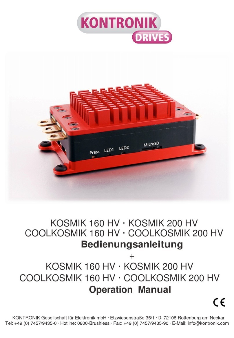
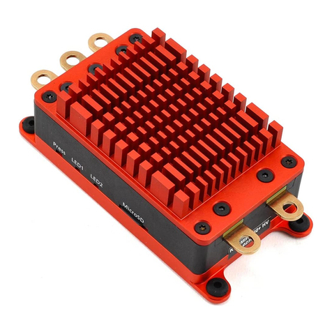
KONTRONIK JIVE Pro 80+ HV Installation manual

JIVE Pro 80+ HV · JIVE Pro 120+ HV
Be
d
i
e
nun
gs
a
n
le
itu
ng
Operation
Ma
nu
a
l
Stand: Juli 2017
Effective: July 2017
KONTRONIK – eine Marke der SOBEK Drives GmbH / KONTRONIK – a brand of SOBEK Drives GmbH
Am Oberfeld 9 – D-72108 Rottenburg am Neckar
Tel: 07457/9435-0 – Fax: 07457/9435-90 – E-Mail: [email protected]

2
Inh
a
l
t
s
ve
r
ze
i
c
hn
i
s
1 Definitionen 2
1.1 Lieferumfang 2
2 Sicherheitshinweise 2
3 Grundlagen 3
3.1 Sender vorbereiten, Gaskurve 3
3.2 Modus Programmierung 3
3.3 Sanftanlauf 3
3.4 Tiefentladungsschutz 3
4 Allgemeines 3
4.1 Eigenschaften 3
4.2 Kühlung und Befestigung 4
4.3 BEC / Betrieb ohne BEC 4
4.4 Ringkern 4
4.5 Aktiver Freilauf 4
4.6 Teillastfestigkeit 4
4.7 Sensorlose Kommutierung 4
4.8 Variable Taktfrequenz 5
4.9 Schutzmechanismen 5
4.10 Heli Modus 5
4.11 Autorotation AR (Bail-out) 5
5. Anschuss der Kabel 5
5.1 BEC-Kabel 6
5.2 Motor Kabel 6
5.3 Sensoranschluss 6
6. Inbetriebnahme 6
6.1 Übersicht und Funktion der Modi 6
7 Modusprogrammierung 6
7.1 Modus 1 - APM 6
7.2 Modus 2 - Segler (mit Bremse) 7
7.3 Modus 3 - Motorflug/Boot (o. Bremse) 7
7.4 Modus 4 - Helikopter 8
7.5 Modus 6 - Vorwärts / Rückwärts 9
7.6 Modus 10 - BEC Spannung 10
8 Update 10
9 Kopplung des Bluetooth Moduls 10
10 Fehlerbehebung 11
10.1 Fehlermeldung beim Anstecken des
Akkus 11
10.2 Fehlermeldung während der
Programmierung 11
10.3 Fehlermeldung im Betrieb 11
11 Technische Hilfe, Beratung, Hotline 12
11.1 Recycling 12
11.2 Gewährleistung 12
1.
D
e
fi
n
i
t
i
o
n
e
n
APM
Auto-Programmier-Modus
EMK Elektromotorische Kraft
EMV Elektromagnetische Verträglichkeit
AR Autorotation / Bail-out
BEC Battery Eliminating Circuit (Schaltung
zur Versorgung des Empfängers aus
dem Antriebsakku)
JIVE Pro JIVE Pro Drehzahlsteller
Jumper Jumper zur Modusprogrammierung
LED Leuchtdiode / Kontrollleuchte
Modus (Modi) Betriebsart / Programm-
parameter veränderbarer Wert
Pitch Blatt-Anstellwinkel (Rotor)
Oberseite siehe Abbildung unter Punkt 5
Unterseite siehe Abbildung unter Punkt 5
1.1 Lieferumfang
1. JIVE Pro Regler
2. 1 x BEC Kabel (JIVE Pro 80+ HV)
3. Anleitung
4. Satz Aufkleber
5. zus. 1x BEC Kabel und 1x Kühlkörper
(bei JIVE Pro 120+ HV)
2. Sicherheitshinweise
Der JIVE Pro ist ein Produkt, das
a
us
-
schließlich für den Modellbaubetrieb
v
or
-
gesehen ist. Keinesfalls darf der JIVE Pro in
bemannten Anwendungen
e
i
n
g
e
s
e
t
z
t
werden
!
Um ein Überhitzen des Reglers zu verhin-
dern ist grundsätzlich auf gute Kühlung zu
achten. Gegebenenfalls einen Kühlkörper
auf der Kühlplatte des JIVE Pro befestigen
!
z.B. KK-JIVE, Art.Nr. 9470
•
Beim Anschließen von Motor und
A
n
t
ri
e
b
sakku
an
den
Regler
ist auf
ausreichenden
S
i
c
h
e
r-
heitsabstand zu allen beweglichen Teilen
(
S
c
hr
a
u
b
e
, Propeller oder
R
o
t
o
r
)
zu achten,
d
a
es durch Fehlbedienung oder elektrischen
De
fekt zum unbeabsichtigten
Anlaufen
des
Mo
t
o
rs kommen kann.
Ein anlaufender
Elektro-
motor
m
i
t
Schraube, Propeller oder Rotor, kann
e
rh
e
b
li
c
h
e
Verletzungen verursachen. Bei
I
n
b
e
t
ri
e
b
n
a
h
m
e
des
Reglers
ist darauf
zu
achten, dass Sach- un
d
Personenschäden
ausgeschlossen sin
d
.
•
Den Regler niemals im laufenden
B
e
t
r
i
e
b
vom
Akku trennen.
•
Um eine Beschädigung zu vermeiden, bei
I
n-
betriebnahme den
Regler
vor
e
l
e
k
t
r
o
s
t
a
t
is
c
h
e
n
Entladungen schützen ggf. auf ausreichende
Erdung
a
c
h
t
e
n.
•
Ein beschädigter Regler
(
z
.
B
. durch
F
e
u
c
h-
tigkeit, mechanische oder elektrische
E
in
w
ir-
k
un
g
)
darf keinesfalls weiter verwendet
w
e
r
-
den, da es ansonsten jederzeit zum Ausfall des
Reglers kommen kann.
•
Der Regler
darf
nur an Akkus betrieben
werden.
Ein Betrieb an Netzgeräten
ist nicht zulässig.
•
Der Regler darf in keinem Fall an das 110 /
230V Wechselstromnetz angeschlossen
w
e
r
d
e
n.
•
Bei Akkus mit hoher Kapazität muss un
b
e
dingt
auf ausreichende Kühlung des Reglers
geachtet
w
e
r
d
e
n.
•
Eine Verlängerung der Akku- oder
Mo
t
o
r
k
a
bel
kann die EMV-Eigenschaften beeinflussen.
!
!

3
Zudem können zu lange Akkukabel zur
Beschädigung des Reglers führen.
•
Eine Verlängerung der Kabel erfolgt daher
auf
e
i
g
e
nes Risiko.
•
Bei Strommessungen ist ein Z
a
n
g
e
n
a
m
p
e
r-
meter zu verwenden. Ein
e
in
g
e
s
c
hl
e
i
f
t
e
s
Messgerät oder -shunt kann den Regler
b
e
s
c
h
ä
d
i
g
e
n.
•
Bei Verwendung des BEC muss aus
Sicherheitsgründen zusätzlich ein geladener,
a
usr
e
i
c
h
e
n
d
großer Empfängerakku verbaut
w
e
r
d
e
n
(
si
e
h
e
BEC 4.3
)
. Fehlfunktionen, z.B.
d
ur
c
h Kabelbruch, Kurzschluss, Wackel-
kontakt
o
d
e
r Ausfall eines BEC-Bauteils,
führen sonst zum Ausfall der gesamten
Empfangsanlage.
•
Vor dem Erstflug muss mittels Tests am
B
o
-
den sichergestellt werden, dass die
B
E
C
-
B
e
lastbarkeit für die Anwendung
a
usr
e
i
c
h
t
.
3. Grundlagen
Die JIVE Pro Regler verfügen über eine
Mo
dus-
programmierung. Der jeweils
g
e
w
ä
hl
t
e
Modus
stellt die für den Betriebszustand
b
e
nötigten
Parameter selbst ein. Eine
P
r
og
r
a
m
mierung der
einzelnen Parameter entfällt normalerweise.
Sollten andere Parameter für einzelne
B
e
triebs-
zustände gewünscht werden,
kö
nn
e
n diese
mittels
geeigneter KONTRONIK
Programmiereinheit
v
e
rändert
w
e
r
d
e
n.
3.1 Gaskurve im Sender zur Vorbereitung der
Reglerprogrammierung
Im Sender wird auf den für das Gas
f
e
s
t
g
e
l
e
g
ten
Kanal eine linear ansteigende Gasgerade von
0% bis 100%
e
in
g
e
s
t
e
ll
t
.
Der Gaskanal kann wahlweise auf einen
Knüppel, Schalter oder Schieberegler gelegt
w
e
r
d
e
n.
3.2 Programmierung des gewünschten
Modus im Regler
Beim Programmieren des gewünschten
Mo
dus
lernt der Regler den am Sender zur Verfügung
stehenden Gasweg ein
(
0
–
100
%
)
. Alle weiteren,
für den gewählten Modus n
o
t
w
e
ndigen
Parameter stellt der JIVE Pro
a
u
t
o
m
a
tisch ein.
Für die Programmierung der Modi sind un
t
e
r
-
schiedliche Schritte notwendig. Die
V
o
r
g
e
hens-
weise entnehmen Sie bitte dem Kapitel 7 in dieser
A
nl
e
i
t
un
g
.
Bitte beachten Sie, Modus 1 bis 6 können
nur über Modusprogrammierung, nicht
über Programmiereinheit, progr
a
mm
i
e
r
t
werden.
3.3 Sanftanlauf
Mittels Sanftanlauf erhöht der Regler beim Start
inn
e
rhalb der eingestellten Zeit die
Mo
t
o
r
d
r
e
h
za
hl.
Die Zeit für das Hochlaufen von 0 % auf 100
%
kann über die
Programmiereinheit
zwischen 8 s und
60 s eingestellt werden
(
De
f
a
ul
t
c
a
.12 s
)
. Je höher
der festgelegte
P
r
o
zentsatz des Gaskanals am
Sender ist,
d
e
s
t
o
höher ist die eingeregelte
Drehzahl.
KONTRONIK
empfiehlt, für optimales Regel-
verhalten eine Regleröffnung von ca. 80
%
im
Sender
(
100
%
entspricht vollem Knü
pp
e
l
w
e
g
)
.
Damit ist gewährleistet, dass der Regler ü
b
e
r
ausreichende Reserve verfügt, um die
a
bf
a
llende
Akkuspannung und Lastspitzen zu
ko
m
p
e
nsi
e
r
e
n.
3.4 Tiefentladungsschutz
Die JIVE Pro Regler sind mit einem Tiefent-
ladungsschutz ausgestattet, der für jede Z
e
ll
e
nzahl
und gewählten Modus die n
o
t
w
e
n
d
i
g
e
n Parameter
automatisch
e
ins
t
e
ll
t
.
Je nach Modus wird der Motor
a
b
g
e
r
e
g
e
l
t
oder
abgeschaltet, wenn die eingestellte
A
k
kuentlade-
spannung erreicht is
t
. Die Abregelzeit im Heli
Modus ist fest
e
in
g
e
stellt und beträgt ca. 60 s. Die
Abregelspannung pro Zelle ist per Programmier-
einheit von
2,7 V - 3,5 V
(
Li
P
o
, default:
3 V)
1,8 V
-
2,6 V
(
Li
F
eP
o
, default: 2,3
V
)
0,7 V - 1,2 V
(
NiC
d
/
Ni
M
H, default 0,8
V
)
in 0,1 V
S
c
hri
tt
e
n
e
ins
t
e
ll
b
a
r.
Sobald die eingestellte
A
br
e
g
e
l
-
/
A
bschaltspan-
nung erreicht wird, leitet d
e
r JIVE Pro entsprech-
end des progr
a
mm
i
e
rten Modus die
U
n
t
e
r
s
p
a
n-
nun
g
s
a
br
e
g
e
l
un
g
/
-
a
b
s
c
h
a
l
t
un
g automatisch ein.
B
i
tt
e
laden Sie den Akku danach wieder auf oder
benutzen Sie einen geladenen Akku.
4. Allgemeines
Sollten Sie Fragen zu Einsatz, Betrieb
o
d
e
r
Programmierung des Reglers haben,
ko
n
t
a
k
tieren
Sie bitte unseren Service.
4.1 Eigenschaften
•
Sensorloser Be
t
r
i
e
b:
der JIVE Pro benötigt
keine Sensorsignale vom Motor. Sensor-
leitungen unbelegt lassen.
•
Mo
d
us
p
rogr
a
mm
i
e
r
un
g
: voreingestellte Pa-
rameter für un
t
e
rs
c
hi
e
d
li
c
h
e A
n
w
e
n
d
un
g
e
n
•
Automatische U
n
t
e
r
s
p
a
nnun
g
s
a
b
r
e
g
e
l
un
g
:
Spannung ist einstellbar
(
si
e
h
e
3.4
)
.
•
Aktiver
F
r
e
il
a
u
f
: unbegrenzt teillastfest,
solange bei Vollgas
d
e
r zulässige Dauerstrom
nicht überschritten
w
ir
d
.
•
Abschaltanalyse: der Abschaltgrund wird durch
Blinkcode
a
ngezeigt.
!

4
•
Einstellkontrolle: per LED und / oder akus-
tischem Signal.
•
Akkuerkennung: beim Anstecken eines Akkus
wird
a
u
t
o
matisch die
Zellenzahl
erkannt und
als
S
i
g
n
al
ton ausgegeben. Die Anzahl der
S
i
g
n
a
l
t
ö
n
e
entspricht der Anzahl der
erkannten Zellen.
Langer Signalton: 4 Zellen
e
r
k
a
nn
t
Kurzer Signalton: 1 Zelle
e
r
k
a
nn
t
B
e
i
s
pi
e
l
:
1 langer + 1 kurzer Ton: 5 Zellen
2 lange + 2 kurze Töne: 10 Zellen
Der JIVE Pro kann die Zellenzahl des Akkus
nur dann korrekt erfassen,
we
nn
dieser beim
Anstecken vollgeladen ist
!
1. Sehr feinfühliges
R
e
g
e
l
v
e
r
h
a
l
t
e
n
: ruckfreier,
sanfter Anlauf.
2. Automatische
Erfassung
der Motorparameter:
angepasste Taktfrequenz
(
32
k
H
z
oder h
ö
h
e
r
),
dynamisches Timing
3. Anlauf-, Blockier- und
Üb
e
r
t
e
m
p
e
r
a
t
u
rs
chutz,
S
t
ro
m
b
e
gr
e
n
z
un
g
4. Digitale
M
i
kro
p
ro
ze
ss
or
s
t
e
u
e
r
un
g
: daher kein
T
e
m
p
e
r
a
t
ur
d
ri
f
t
.
5. Bitte beachten Sie, dass der JIVE Pro
n
i
c
h
t
PROGCARD kompatibel
i
s
t
.
6. Updatefähigkeit: Firmwareupdate online, via
KONTRONIK Updateeinheit.
7. 24 Monate
G
e
w
ä
h
r
l
e
i
s
t
un
g
: für Geräte mit
gültigem EU-Kaufbeleg.
8. CE
g
e
p
r
ü
f
t
9. Schneller
R
e
p
a
r
a
t
u
r
s
e
r
v
i
c
e: in unserem
hauseigenen Service Center.
10. Kostenlose H
o
t
li
n
e: während der täglichen
Telefonzeiten. Infos zu den Telefonzeiten
un
t
e
r: www.kontronik.com
(
Se
rvi
c
e
-
C
e
n
t
e
r
)
11. Entwickelt und gefertigt in
R
o
tt
e
n
b
u
rg
,
De
u
t
s
c
h
l
a
n
d
.
4.2 Kühlung und Befestigung
Ausreichende Kühlung verbessert den
W
irkungs-
grad und die Lebensdauer des JIVE Pro. Die
Leistungsfähigkeit wird mit
z
un
e
hmender Kühlung
stark
e
rh
ö
h
t
.
Der Regler sollte so im Modell fixiert
w
e
r
d
e
n
,
dass die Kühlplatte oder der montierte
K
üh
l
körper nach außen zeigt. Bei Montage des
Kühlkörpers auf guten K
o
ntakt mit der Kühlplatte
des Reglers
a
c
h
t
e
n. KONTRONIK empfiehlt zur
Fixierung
d
e
s Kühlkörpers dünnflüssigen
Se
k
un
d
e
n
k
l
e
b
s
t
o
ff
um eine direkte
Kühlanbindung zu erreichen.
4.3 BEC
JIVE Pro Regler verfügen über ein
g
e
t
a
k
tetes
BEC. Dabei ist die Belastbarkeit des JIVE Pro-
BECs weitgehend unabhängig von
d
e
r
Eingangsspannung. Die Verwendung des BECs
ist bei allen Betriebsspannungen möglich.
Es
zeichnet sich durch eine ü
b
e
rdur
c
hschnittliche
Störunterdrückung aus.
BEC-Belastbarkeit
JIVE Pro
8 A
Da
u
e
rs
t
r
o
m
20 A Spitzens
t
r
o
m
BEC-S
p
a
nnun
g: (default 5,6 V)
Auf Wunsch kann die BEC Spannung
m
i
tt
e
ls
Programmiereinheit in 0,1 V Schritten von 5 V bis
8 V eingestellt
w
e
r
d
e
n.
Aus Sicherheitsgründen muss
e
n
t
we
d
e
r ein
2-zelliger LiFePo Akku
(
e
in
z
us
t
e
ll
e
n
d
e
BEC Spannung: 6,6
V
–
7
V
)
oder ein 2-zelliger LiPo Akku
(
e
in
z
us
t
e
ll
e
n
d
e
BEC Spannung: 8
V
)
oder ein 4-zelliger NiCd Akku
(
e
in
z
us
t
e
llende
BEC Spannung: 5,6
V
)
am Empfänger ange-
steckt
w
e
r
d
e
n.
ACHTUNG:
Vorab bitte die Spezifikationen der
Akkus, der Servos und Empfänger auf Kom-
patibilität zur gewünschten Spannung prüfen
!
Betrieb ohne
BE
C
:
Beim Betrieb ohne BEC ist das rote
Empfän
gerkabel ( + ) aus dem Fernsteuerstecker
zu
z
i
e
hen oder zu
d
ur
c
h
t
r
e
nn
e
n.
4.4 Ringkern
Der werkseitig angebrachte Ringkern im
E
m
p
fängeranschlusskabel dient der
S
t
ö
run
t
e
r-
drückung und ist für die
B
e
t
ri
e
b
ssi
c
h
e
rh
e
i
t
des
Reglers notwendig. Er darf nicht
e
n
t
f
e
rn
t
werden,
kann aber bei Bedarf innerhalb
d
e
s Kabels
verschoben
w
e
r
d
e
n.
Ringkern
nicht
entfernen!
Verschieben
innerhalb
des
Kabels
möglich. Nach dem
Verschieben,
auf feste
Umwicklung
des
Ringkerns
achten.
4.5 Aktiver Freilauf
Mit dem aktiven Freilauf wird der
W
ir
k
un
g
sgrad im
Teillastbereich
o
p
t
i
m
i
e
r
t
. Dadurch verringert sich
die Erwärmung
d
e
s
Reglers.
Bei geringer Last wird
der aktive Freilauf abgeschaltet, was zu einem
kleinen
D
r
e
hzahlsprung führen kann.
4.6 Teillastfestigkeit
Der JIVE Pro ist durch seinen aktiven Freilauf voll
!
!
!

5
teillastfest, solange bei Vollgas und
V
o
lllast der
Akkustrom die zulässige
Da
u
e
rs
t
r
o
m
grenze nicht
ü
b
e
rs
c
hr
e
i
t
e
t
.
4.7 Sensorlose Kommutierung
Der JIVE Pro benötigt keine Sensoren im
Mo
tor,
er arbeitet mit einem 3D K
e
nn
f
e
l
d
. Die
Anpassung an
d
e
n Motor und den
Betriebszustand erfolgt
a
u
t
o
matisch und ist somit
d
yn
a
m
is
c
h.
4.8 Variable Taktfrequenz
Der JIVE Pro verwendet eine Taktfrequenz von
32 kHz oder höher. Je nach Anforderung
w
ir
d
sie
automatisch angepasst. Die Höhe der
T
a
k
t
-
frequenz ist abhängig vom verwendeten
Mo
t
o
r
und der momentanen Belastung. Die
T
a
k
t
f
r
e
quenz wird optimal auf die anliegenden
Parameter abgestimmt.
Der
Motor arbeitet somit
i
m
mer im Bereich des optimalen
W
ir
k
un
g
s
g
r
a
d
e
s.
4.9 Schutzmechanismen
Im JIVE Pro sind folgende
S
c
hu
t
z
m
e
c
h
a
nismen
a
k
t
ivi
e
r
t
:
12. Wird länger als 2 s kein
g
ül
t
i
g
e
s Empfangs-
signal erkannt, schaltet der Regler den Motor
ab. Der Wert kann per Programmiereinheit
von 1–4 s eingestellt
w
e
r
d
e
n.
•
Bei Übertemperatur wird das Gas langsam
(
c
a
. 60
s
)
auf null
z
urü
c
kg
e
r
e
g
e
l
t
.
•
die Unterspannungserkennung führt in
Mo
d
us 1 und 2
(
AP
M
und
Se
g
l
e
r
)
zur
Abschaltung un
d
in Modus 3 bis 6
(
Mo
t
o
r
f
lu
g
, Heli, RC C
a
r
)
zu einer langsamen
A
b
r
e
g
e
lun
g
.
Wenn der JIVE Pro die Drehzahl im Heli
Modus herunter geregelt hat, ist kein
d
i
r
ek
tes Hochfahren mehr möglich. Erst
nach Anstecken eines g
e
l
a
d
e
n
e
n
Akkus
wird der Betrieb wieder fr
e
i
g
e
g
e
b
e
n
.
4.10 Heli Modus
Im Heli Modus ist die Drehzahlregelung
a
k
t
iv.
Die Motordrehzahl wird konstant gehalten. Last-
schwankungen und das Absinken der A
k
kuspan-
nung werden kompensiert, solange
d
i
e
Leistung
des Akkus und des Motors
d
a
f
ür ausreichen. Es
wird kein separater
M
is
c
h
e
r der Fernsteuerung
benötigt, um die
R
o
t
o
rdrehzahl zu s
t
a
b
ilisi
e
r
e
n.
Die Drehzahlregelung funktioniert nur im
eingebauten Zustand. Wird der Motor ohne
die Schwungmasse des Rotors b
e
t
r
i
e
b
e
n
,
kann ein ruckender Betrieb
e
n
t
s
t
e
h
e
n
.
Empfehlenswert ist, beim Hochlaufen immer auf
0° Pitch zu stellen, damit die
Drehzahl
bei j
e
d
e
m
Flug annähernd gleich is
t
.
Zum Starten des Motors den zuvor
f
e
s
t
g
e
l
e
g
t
e
n
Schalter
(
si
e
h
e
Punkt 3.1
)
auf die Idle 1
P
o
si
t
i
o
n
stellen. Mittels Sanftanlauf erhöht der Regler
innerhalb der eingestellten Hochlaufzeit
d
i
e
Motordrehzahl
(
E
ins
t
e
llun
g
siehe 3.3
)
.
Wenn die vorher eingestellte
Mo
t
o
r
d
r
e
h
za
hl
erreicht ist, schaltet der Regler
a
u
t
o
m
a
t
is
c
h auf
Regelbetrieb. Je höher die im Sender hinterlegte
Prozentzahl für den
F
lu
g
z
us
t
a
n
d
(
si
e
h
e
3.1
)
, desto
höher ist die eingeregelte Drehzahl.
Wird die Gasvorwahl am Sender auf
Mo
t
o
r
-
Aus
Stellung zurückgestellt, schaltet der
Mo
tor aus. Die
Motor-Aus Stellung sollte
w
ä
hrend des Fluges nicht
angewählt werden, da zum Wiederanfahren des
Motors durch den Sanftanlauf die eingestellte
Hochlaufzeit (siehe Punkt 3.3) benötigt wird.
Eine Ausnahme stellt der Modus 4 mit Autorotation
dar, da beim Zurückschalten von Autorotation auf
Normalbetrieb der Rotor per Schnellanlauf
beschleunigt wird.
4.11 Auto Rotation (Bail-out)
Durch die
A
u
t
o
r
o
t
a
t
i
o
ns
-
S
c
hn
e
ll
a
nl
a
u
f
-
F
un
k
tion
läuft der Motor in
d
e
u
t
li
c
h kürzerer Zeit wieder an
und bringt den
R
o
t
o
r schneller auf Drehzahl.
Dadurch sind
a
b
ru
p
t
e
Abfangmanöver
m
ög
li
c
h.
Die Hochlaufzeit nach Bail-out ist dabei von der
eingestellten Hochlaufzeit abhängig. Sie wird
automatisch errechnet und liegt bei 2 - 6 s.
Die AR Position ist zuvor am Sender bei 25 %
einzustellen
(
si
e
h
e
3.1
)
und muss nicht separat am
JIVE Pro programmiert werden
(
si
e
h
e
Abb. in 7.4
)
.
Bei Anwahl der definierten AR Position im l
a
u-
fenden Betrieb wird der Motor
a
b
g
e
s
c
h
a
l
t
e
t
und die
AR Funktion ist aktiviert. Wird die AR Funktion
durch Idle 1, Idle 2, Idle x
b
e
endet, schaltet der
Motor wieder ein und
d
i
e Drehzahl
wird im
Schnellanlauf auf den vorher eingestellten Wert
h
o
c
h
g
e
f
a
hr
e
n.
Wird die aktive
AR
Funktion abgebrochen un
d
der
Motor ausgeschaltet, aktiviert der JIVE Pro beim
anschließenden Motorstart den r
e
gulären Sanft-
anlauf.
5. Anschluss der Kabel
ACHTUNG:
Die Montage muss immer
stromlos (kein angeschlossener Akku)
erfolgen.
!
!
!
Jumperkabel
Empfänger (beliebiger
Steckplatz)
Empfänger (Kanal
mit Gasfunktion)

6
5.1 BEC-Kabel
Am
JIVE Pro
können leistungsstarke
Digitalservos mit folgender Spezifikation
betrieben werden:
8 A
Da
u
e
rs
t
r
o
m
20 A Spitzenstrom
Um den vollen BEC-Strom bereitstellen zu
können, verfügen alle JIVE Pro-Regler ü
b
e
r zwei
BEC Buchsen. Bei BEC-Strömen ü
b
e
r 5 A
müssen beide Buchsen belegt sein.
•
Die mit
„Master“
gekennzeichnete
B
u
c
hs
e
muss an den Empfängerkanal
a
n
g
e
s
c
hl
o
ss
e
n
werden der die Gasfunktion ü
b
e
rni
mm
t
.
•
Die mit
„Slave“
gekennzeichnete
B
u
c
hs
e
kann mit jedem beliebigen freien
E
m
pf
ä
n
-
g
e
r
k
a
nal verbunden werden.
Das
passende
B
E
C
-
K
a
bel
(
B
e
s
t
. Nr.: 9250
)
ist als Zubehör
e
rh
ä
l
t
li
c
h. Die BEC-Spannung kann
m
i
tt
e
ls
Programmiereinheit in 0,1V-Schritten von 5 V
bis 8 V eingestellt
w
e
r
d
e
n.
5.2 Motor-Kabel
Der Anschluss der 3 Motorkabel ist
b
e
li
e
b
i
g
. Das
Tauschen von 2 Motorkabeln ändert
d
i
e
Motor-
drehrichtung. Alternativ kann die
Mo
t
o
rdreh
-
richtung über
die
Programmiereinheit
geändert
w
e
rden. Sollte der verwendete Motor über
Se
nsorleitungen verfügen, so werden diese ni
c
h
t
benötigt und bleiben un
b
e
l
e
g
t
.
5.3 Sensor Anschluss
Der Sensoranschluß dient dem Anschluss der
externen Module für Telemetrie, Bluetooth, o.Ä..
6. Inbetriebnahme
An den BEC- sowie den Akkukabeln
m
üs
sen verpolungssichere Stecker
v
e
r
we
n
d
e
t
werden, da eine Verpolung
i
rr
e
p
a
r
a
b
l
e
Schäden hervorruft!
6.1 Übersicht und Funktionsumfang der
programmierbaren Modi
7. Programmiermodus
7.1 Modus 1 - APM (Reset)
Die Programmierung mit Modus 1 löscht alle vorher
getätigten Einstellungen.
1. Sender einschalten und vorbereiten
(
w
i
e
ab 3.1
b
e
s
c
hri
e
b
e
n
)
. Gas-/Pitchknüppel auf Stellung
„Motor-Aus“
(
0
%
)
stellen.
2. Den JIVE Pro mit dem Empfänger
(
B
E
C
-
K
a
b
e
l
)
verbinden. Das Kabel für den
Ga
s
k
a
nal
in die mit
„Master“
gekennzeichnete Buchse
stecken. Empfänger
e
ins
c
h
a
l
t
e
n. Jumperkabel
aufstecken.
3. Motorkabel mit dem Motor
v
e
r
bi
n
d
e
n
.
4. Antriebsakku a
ns
c
h
li
e
ß
e
n
.
5. LED blinkt 1 Mal. Es
e
r
k
lin
g
t
der ansteigende
Dreiklangton als
E
ins
c
h
a
l
t
bestätigung und
anschließend Einzeltöne
f
ür die erkannte
Zellenzahl
(
si
e
h
e
4.1
)
.
6. Das Jumperkabel abziehen. Es erklingt ein
absteigender
D
r
e
i
k
l
a
n
g
t
o
n, die LED blinkt 1
Mal.
7. Der JIVE Pro beginnt den Modus a
us
z
u
g
eben.
Er beginnt mit einem Ton und erhöht die
Einzeltöne je Modus. Die LED blinkt
e
n
t
sprechende der Anzahl Modustöne.
Modus
EMK-Bremse
Knüppelwege fest
Unterspannungs-
abregelung
Unterspannungs-
abschaltung
Drehzahlregelung
Autorotation
1 APM
2 Seglermodus
(Stellerbetrieb)
3 Motorflug / Boot
Modus
(Stellerbetrieb)
4 Heli Modus mit
Drehzahlregelung
6 Vorwärts / Rückwärts
!

7
8. Nach dem ersten Einzelton ist Modus 1 e
r
-
reicht; den Gashebel auf Vollgas
(
100
%
)
s
t
e
llen. Der JIVE Pro bestätigt die
Gasposition mit ansteigenden Dreiklang und
den
Mo
d
us mit einem Einzelton.
Vor dem Trennen des Reglers vom Akku
unbedingt die Modusbestätigung
a
b
wa
r
t
e
n
(Schritt 8), da der Regler sonst eine nicht
abgeschlossene Programmierung
e
r
ke
nn
t
und gesperrt wird. Auf eventuelle Ausgabe
der Warnmeldung 9-fach Blinken achten
!
7.2 Modus 2 - Segler
Modus 2 arbeitet im reinen Stellerbetrieb ü
b
e
r
den gesamten Gasweg hin
w
e
g
.
Die automatische EMK Bremse ist aktiv,
d
i
e
Intensität ist über Programmiereinheit
s
t
u
f
e
n
w
e
is
e
einstellbar
(
v
o
n 0 % bis 100 %, der
Default Wert ist 92
%
)
.
Die Unterspannungsabschaltung
(
T
i
e
f
e
n
t
l
a
d
un
g
s-
s
c
hu
t
z
)
ist in Modus 2 aktiv, dabei
w
ir
d
der Motor
ausgeschaltet, wenn die
e
in
g
e
stellte Akkuentlade-
spannung erreicht is
t
.
Modus 2 progr
a
mm
i
e
r
e
n
:
1. Sender einschalten und vorbereiten
(
w
i
e
ab
3.1
b
e
s
c
hri
e
b
e
n
)
. Gasknüppel auf
S
t
e
llun
g
„Motor-Aus“
(
0
%
)
stellen.
2. Den JIVE Pro mit dem Empfänger
(
B
E
C
-
K
a
b
e
l
)
verbinden. Das Kabel für den
Ga
s
k
a
nal
nur in die mit
„Master“
gekennzeichnete
Buchse stecken. Empfänger
e
ins
c
h
a
l
t
e
n.
Jumperkabel aufstecken
3. Motorkabel mit dem Motor
v
e
r
bi
n
d
e
n
.
4. Antriebsakku am JIVE Pro a
ns
c
h
li
e
ß
e
n
.
5. LED leuchtet. Es
e
r
k
lin
g
t
ein ansteigender
Dreiklangton als
E
ins
c
h
a
l
t
bestätigung und
anschließend
Einzeltöne
f
ür die erkannte
Zellenzahl
(
si
e
h
e
4.1
)
.
6. Das Jumperkabel abziehen, es erklingt ein
absteigender
D
r
e
i
k
l
a
n
g
t
o
n, die LED leuchtet
auf.
7. Der JIVE Pro beginnt die Modi a
us
z
u
g
eben, je
Modus die entsprechende Anzahl Einzeltöne,
die L
E
D
blinkt
e
n
t
sprechend der Anzahl
Modustöne.
8. Nach dem 2. Einzelton ist Modus 2 e
r
reicht,
den Gashebel auf Vollgas
(
100
%
)
s
t
e
llen. Der
JIVE Pro bestätigt die Gasposition mit
e
inem
B
e
s
t
ä
t
i
g
ungs
t
o
n.
9. Um eine separate Motor-Aus-Stellung zu
p
r
o-
grammieren, den Gashebel in die
g
e
w
üns
c
h
t
e
Position bringen
(
z
.
B
. 50
%
)
, der JIVE Pro
b
e
stätigt mit einem ansteigenden Dreiklang
un
d
den Modus mit 2 Einzeltönen. Damit sind
i
m
JIVE Pro 3 Stellungen
p
r
og
r
a
mm
i
e
r
t
:
Vollgas
(
z
.
B
. 100
%
)
, Motor Aus
(
z
.
B
. 50
%
)
un
d
Bremse
(
a
u
t
o
m
a
t
is
c
h bei Gashebel
M
ini
m
u
m
)
.
Sollte die optionale Motor-Aus Position ni
c
h
t
gesetzt werden, bremst der JIVE Pro
b
e
i der
minimum
P
o
si
t
i
o
n.
Vor dem Trennen des Reglers vom Akku
unbedingt die Modusbestätigung
a
b
wa
r
t
e
n
(Schritt 8), da der Regler sonst eine nicht
abgeschlossene Programmierung
e
r
ke
nn
t
und gesperrt wird. Auf eventuelle Ausgabe
der Warnmeldung 9-fach Blinken achten
!
7.3 Modus 3 - Motorflug
In diesem Modus arbeitet der JIVE Pro im r
e
inen
Stellerbetrieb, aber im Gegensatz zu
Mo
dus 2
ohne EMK Bremse.
Die Unterspannungsabregelung
(
T
i
e
f
e
n
t
l
a
d
un
g
s-
s
c
hu
t
z
)
regelt dabei den Motor
a
b
, wenn die
eingestellte
A
kk
u
e
n
t
l
a
d
e
s
p
a
nnun
g
erreicht ist
(
si
e
h
e
3.4
)
.
Modus 3 progr
a
mm
i
e
r
e
n
:
1. Sender einschalten. Gasknüppel auf
S
t
e
llun
g
„Motor-Aus“
(
0
%
)
stellen.
2. Den JIVE Pro mit dem Empfänger
(
B
E
C
-
K
a
b
e
l
)
verbinden. Das Kabel für den
Ga
s
k
a
nal
in die mit
„Master“
gekennzeichnete Buchse
stecken. Empfänger
e
ins
c
h
a
l
t
e
n. Jumperkabel
aufstecken.
3. Motorkabel mit dem Motor
v
e
r
bi
n
d
e
n
.
4. Antriebsakku an JIVE Pro a
ns
c
h
li
e
ß
e
n
.
5. LED blinkt rot. Es
e
r
k
lin
g
t
ein ansteigender
Dreiklangton als
E
ins
c
h
a
l
t
bestätigung und
anschließend Einzeltöne
f
ür die erkannte
Zellenzahl
(
si
e
h
e
4.1
)
.
6. Das Jumperkabel abziehen. Es erklingt ein
absteigender
D
r
e
i
k
l
a
n
g
t
o
n, die LED leuchtet.
7. Der JIVE Pro beginnt die Modi a
us
z
u
g
eben, je
Modus die entsprechende Anzahl Einzeltöne,
die LED blinkt
e
n
ts
prechend der Anzahl
Modustöne.
8. Nach dem 3. Einzelton ist Modus 3 e
r
reicht,
den Gashebel auf Vollgas
(
100
%
)
s
t
e
llen. Der
JIVE Pro bestätigt die Gasposition mit
e
inem
ansteigenden Dreiklang und 3 Einzeltönen.
Vor dem Trennen des Reglers vom Akku
unbedingt die Modusbestätigung
a
b
wa
r
t
e
n
(Schritt 8), da der Regler sonst eine nicht
abgeschlossene Programmierung
e
r
ke
nn
t
und gesperrt wird. Auf eventuelle Ausgabe
der Warnmeldung 9-fach Blinken achten
!
!
!
!

8
7.4 Modus 4 Helikopter
Drehzahlvorwahl
beim
JIVE Pro
... JIVE Pro abwärts
Jive Pro aufwärts
Autorotation
Der Heli-Modus arbeitet mit einer echten
D
r
e
hzahlregelung
(
G
o
v
e
rn
o
r
)
. Unabhängig von
d
e
r Belastung wird die Motordrehzahl konstant
g
e
halten, solange Akku- und Motorleistung
d
i
e
s
zulassen. Der Regler lernt alle Parameter
d
e
r
Programmierung, wie das Verhältnis von
D
r
e
h-
zahlvorwahl am Sender und Rotordrehzahl
b
e
i
jedem Anstecken des Akkus neu ein.
Wird per Programmiereinheit die Funktion
„
G
o
v
e
rn
o
r
Store“
aktiviert, lernt der JIVE Pro
diese Parameter nur einmal ein. Beim ersten
H
o
c
hl
a
u
f
e
n werden diese
Parameter
dann fest
g
e
s
p
e
i
c
h
e
r
t
. Bei Verwendung verschiedener
Akkus
m
i
t
gleicher
Zellenzahl
werden damit
r
e
p
r
o
d
u
z
i
e
rbare, gleichbleibende Drehzahlen
e
rr
e
i
c
h
t
. Verschiedene Zellenzahlen des
A
n
triebsakkus können damit jedoch nicht
kompensiert werden.
Es ist daher nicht
z
ulässig im
„
G
o
v
e
rn
o
r
Store“
z.B. mit einem 10S
A
kk
u zu programmieren und
dann mit 12S Akku zu fliegen.
Bei Änderungen am Setup (Motor,
Ü
b
e
rsetzung, Rotorblättern etc.) muss auf
jeden Fall Modus 4 mit Governor Store neu
programmiert
we
rd
e
n
!
Die Autorotation
(
B
a
il
o
u
t
)
ist fester
B
e
s
t
a
n
d
teil
von Modus 4. Er kann nicht wahlweise
m
i
t
oder
ohne AR programmiert
w
e
r
d
e
n. Wird kein Bailout
gewünscht muss dies über die Gasvorwahl
verhindert werden. (siehe vorangegangen
Graphik)
Im Modus 4 ist die Un
t
e
rs
p
a
nnun
g
s
a
b
r
e
g
e
lung
(
T
i
e
f
e
n
t
l
a
d
un
g
ss
c
hu
t
z
)
aktiv und r
e
g
e
l
t
dabei
den Motor ab, wenn die eingestellte
A
k
kuentladespannung erreicht ist
(
si
e
h
e
3.4
)
.
Der Sanftanlauf ist auf 12 s v
o
r
e
in
g
e
stellt und
kann über
die Programmiereinheit
von 8 – 60
s
variiert
w
e
r
d
e
n.
Die BEC Spannung ist variabel und kann
p
e
r
Programmiereinheit in 0,1 V Schritten von 5 V
bis 8 V eingestellt werden
(
si
e
h
e
4.3
)
.
Sender für
den
Heliflug
v
o
r
b
e
r
e
i
t
e
n
Auf dem Gaskanal können mit einem
F
lu
g-
phasenschalter unterschiedliche Drehzahlen
abgerufen werden. Abhängig von der
S
t
e
llun
g
des
Schalters können unterschiedliche
D
r
e
hzahlen
geflogen
w
e
r
d
e
n.
Beispiel Setup für Heli
Mo
d
us
:
Motor-Aus: 0
%
Schweben
(
I
d
l
e
1
)
: 45
%
Rundflug
(
I
d
l
e
2
)
: 60
%
3D-Flug 80
%
Es sollten mind. 20% Reserve für den
R
e
gler eingeplant werden, da sonst eine
a
us
reichende Drehzahlregelung bei
sinkender Akkuspannung oder starken
Lastschwankungen nicht g
ewä
h
r
l
e
i
s
t
e
t
werden kann.
Für die AR Position ist am Sender eine
V
o
rwahl
von 25% vorzusehen. Mit der Vorwahl dieses
Wertes ist die AR Funktion v
o
r
b
e
r
e
i
t
e
t
.
Genaue
Angaben zur
Se
n
d
e
r
p
r
og
r
a
mm
i
e
run
g
entnehmen
Sie bitte der
B
e
d
i
e
nun
g
s
a
nl
e
i
t
un
g
des verwen-
deten Senders.
Modus 4 progr
a
mm
i
e
r
e
n
:
Für
die Nutzung der AR-Funktion ist
z
us
ä
t
z
li
c
h zur
„Vollgas-Position“
100 % und der
„
Mo
t
o
r
-
A
us
-
P
o
sition“
0 % die Programmierung
einer
„
A
R
-
A
n
-
P
o
sition“
bei 25 % korrekt im Sender zu setzen.
Schritt 1: Für die anschließende
Mo
d
us
p
r
o-
grammierung werden nur zwei Positionen
b
e
n
ö
t
i
g
t
:
2
1. Position
= 0%
= Motor aus
2. Position
= 100% =Vollgas
1
1. Überprüfen Sie im Sender, ob die Werte auch
a
ngefahren werden
(
si
e
h
e
auch ab 3.1
)
.
2. Sender einschalten und den vorher pro-
grammierten Schalter auf Stellung
„
Mo
t
o
r
-
Aus“
(
0
%
)
stellen.
3. Den JIVE Pro mit dem Empfänger
(
B
E
C
-
K
a
b
e
l
)
verbinden.
Das
Kabel für den
Ga
skanal in die
mit
„Master“
gekennzeichnete Buchse
stecken. Empfänger
e
ins
c
h
a
l
t
e
n. Jumperkabel
aufstecken.
4. Motorkabel mit dem Motor v
e
r
b
in
d
e
n
(
a
u
f
Drehrichtung des Motors achten, ev.
Mo
t
o
rkabel tauschen oder über
Programmiereinheit ändern
)
.
!

9
5. Antriebsakku anschließen.
6. LED blinkt.
Es
e
rklingt
e
in
ansteigender
Dreiklangton
a
ls
E
ins
c
h
a
l
t
bestätigung und
anschließend
Einzeltöne
für
d
i
e
erkannte
Zellenzahl
(
si
e
h
e
dazu auch 4.1
)
.
7. Jumperkabel abziehen. E
s
erklingt
ein
absteigender
D
r
e
i
k
l
a
n
g
ton,
LED
leuchtet.
8. Der JIVE Pro beginnt die Modi
a
uszugeben,
je Modus die entsprechende Anzahl
Einzeltöne, die L
E
D
b
lin
k
t
entsprechend der
Anzahl Modustöne.
9. Nach dem 4. Einzelton ist
Mo
d
us
4 erreicht,
den Schalter auf Vollgas
(
100
%
)
stellen. Der
JIVE Pro bestätigt die
Vollgasposi
tion mit
einem ansteigenden Dreiklang un
d
danach
den Modus mit 4 Einzeltönen.
2. Position
= 100% =Vollgas
10. Nach Ausgabe der
Mo
d
us
b
e
s
t
ä
t
igung einen
kurzen Moment warten und
d
e
n Regler vom
Akku trennen.
Vor dem Trennen des Reglers vom Akku
unbedingt die Modusbestätigung
a
b
wa
r
t
e
n
(Schritt 8), da der Regler sonst eine nicht
abgeschlossene Programmierung
e
r
ke
nn
t
und gesperrt wird. Auf eventuelle Ausgabe
der Warnmeldung 9-fach Blinken achten
!
Achtung:
Nach abgebrochener
A
u
t
oro
t
a
tion
ergeben sich durch das schnelle
Hochfahren hohe Belastungen für die
M
e
chanik. Hauptrotorblätter fest anziehen.
In Modus 4 mit AR f
li
e
g
e
n
:
Sender für Flug vorbereiten
(
si
e
h
e
3.1
)
.
D
ur
c
h
die Autorotations-Schnellanlauf-Funktion l
ä
u
f
t
der Motor nach einer abgebrochenen
o
d
e
r
missglückten Autorotation in deutlich kürzerer
Zeit wieder an und bringt den Rotor schneller auf
Drehzahl
(
si
e
h
e
4.11
)
. Dadurch sind
unvermittelte
Abfangmanöver
m
ög
li
c
h.
Die Hochlaufzeit ist dabei von der zu
b
e
schleunigenden Masse abhängig und s
t
e
ll
t
sich automatisch auf die aktuellen
Ge
g
e
b
e
nheiten ein. Dadurch steht immer der
s
c
hn
e
lls
t
mögliche Anlauf zur Verfügung, ohne
d
a
b
e
i die Mechanik zu ü
b
e
rl
a
s
t
e
n.
Der Motor wird bei Aktivierung der AR ohne
Verzögerung abgeschaltet. Sollte die
A
u
t
o
r
o
tation unterbrochen, und der Motor
w
i
e
d
e
r
eingeschaltet werden, fährt der JIVE Pro
d
i
e
Drehzahl im Schnellanlauf wieder auf die
z
uvor
angewählte Drehzahl h
o
c
h.
Bleibt der Schalter länger als 90 s in der
Autorotationsposition, wird beim erneuten Hoch-
fahren der Drehzahl wieder der
Sa
n
f
t
a
nlauf
a
k
t
ivi
e
r
t
.
7.5 Modus 6 – Vorwärts / Rückwärts
Der Vorwärts / Rückwärts Modus verfügt darüber
den Motor im Betrieb vorwärts und rückwärts
laufen zu lassen. (Default: aus, über
Programmiereinheit einschaltbar).
Das Ansprechverhalten ist werkseitig auf einen
Mit
telwert programmiert. E
s kann
mittels
Programmiereinheit von „schnell“ bis „träge“
verändert werden. Der Modus 6 arbeitet im
Stellerbetrieb
. Die Un
t
e
rs
p
a
nnun
g
s
a
b
r
e
g
e
lun
g
regelt, wenn die eingestellte
A
kk
u
e
n
t
l
a
d
e-
s
p
a
nnung erreicht ist
(
si
e
h
e
3.4
)
den Motor ab. Die
im Modus 6 integrierte Bremse (EMK-Bremse)
arbeitet mit proportional ansteigender Kraft (d.h.
die Bremsstärke ist Drehzahlabhängig).
Die Motor-Aus Position befindet sich in der
Neu
tralstellung des Knüppelweges (Mittelstellung).
Die am Sender definierte Vollgasrichtung gibt
Vorwärts, die Gegenrichtung Rückwärts vor. Die
Knüppelstellung wird vom JIVE Pro automatisch
erkannt.
Modus 6 progr
a
mm
i
e
r
e
n
:
1. Sender einschalten und vorbereiten
(
w
i
e
ab 3.1
b
e
s
c
hri
e
b
e
n
)
. Gasknüppel auf
S
t
e
llun
g
„Motor-
Aus“
(
0
%
)
stellen.
2. Den JIVE Pro mit dem Empfänger
(
B
E
C
-
K
a
b
e
l
)
verbinden. Das Kabel für den
Ga
s
k
a
nal nur in
die mit
„Master“
gekennzeichnete Buchse
stecken. Empfänger
e
ins
c
h
a
l
t
e
n. Jumperkabel
aufstecken.
3. Motorkabel mit dem Motor
v
e
r
bi
n
d
e
n
.
4. Antriebsakku an JIVE Pro a
ns
c
h
li
e
ß
e
n
.
5. LED blinkt. Es
e
r
k
lin
g
t
ein ansteigender
Dreiklangton als
E
ins
c
h
a
l
t
bestätigung und
anschließend Einzeltöne
f
ür die erkannte
Zellenzahl
(
si
e
h
e
4.1
)
.
6. Jumperkabel abziehen. Es erklingt ein
absteigender
D
r
e
i
k
l
a
n
g
t
o
n, die
LED
leuchtet.
7. Der JIVE Pro beginnt die Modi a
us
z
u
g
eben, je
Modus die entsprechende Anzahl Einzeltöne,
die L
E
D
blinkt
e
n
t
sprechend der Anzahl
Modustöne.
8. Nach dem 6. Einzelton ist Modus 6 e
r
reicht, den
Gashebel auf Vollgas
(
100
%
)
s
t
el
len. Der JIVE
Pro bestätigt die Gasposition mit
e
inem
Bestätigungston. Danach den Gashebel in
Rückwärtsposition
(
0
%
)
stellen, der JIVE Pro
bestätigt mit einem ansteigenden
D
r
e
iklang und
den Modus mit 6 Einzeltönen.
Vor dem Trennen des Reglers vom Akku
unbedingt die Modusbestätigung
a
b
wa
r
t
e
n
(Schritt 8), da der Regler sonst eine nicht
abgeschlossene Programmierung
e
r
ke
nn
t
und gesperrt wird. Auf eventuelle Ausgabe
!
!
!

10
der Warnmeldung 9-fach Blinken achten.
7.6 Modus 10 - BEC Spannung
Der JIVE Pro wird serienmäßig mit einer BEC
Ausgangsspannung von 5,6 V ausgeliefert.
Diese kann über die Updateeinheit oder über
Modus 10 im Bereich 5 - 8 V verändert werden.
Modus 10 progr
a
mm
i
e
r
e
n
:
1. Schritte 1-7 Analog den vorherigen Modi
8. Nach dem 10. Einzelton ist Modus 10
e
r
reicht, den Gashebel auf Vollgas
(
100
%
)
s
t
el
len. Der JIVE Pro bestätigt die
Gasposition mit
e
inem Bestätigungston.
9. Danach wir die BEC Spannung eingestellt.
Begonnen wird mit 5 V (kein Ton). Je
Piepton wird die Spannung um 0,2 V
erhöht. Ist die gewünschte Spannung
erreicht, den Gashebel in Leerlaufposition
(0 %) bringen. Die eingestellte Spannung
wird durch einen ansteigenden
D
r
e
iklang
und die entsprechende Anzahl Pieptöne für
die eingestellte BEC Spannung bestätigt.
Das Erreichen der max. 8 V Ausgangsspannung
markiert ein Mehrfachton. Auch die 8 V Einstel-
lung muss durch Anfahren der Leerlaufposition
innerhalb 2 s bestätigt werden. Ansonsten bleibt
der ursprüngliche BEC Spannungswert erhalten.
8. Update
Auf JIVE Pro Drehzahlstellern können ohne Ein-
senden des Produktes zu KONTRONIK neue
Softwareversionen installiert werden.
V
o
raus-
setzungen für die Durchführung eines U
p
dates
sin
d
:
•
JIVE Pro Drehzahlsteller
•
KONTRONIK
Updateeinheit (Art.Nr. 9311)
•
PC mit Windows™ - Betriebssystem
•
I
n
t
e
rn
e
t
v
e
r
b
in
d
un
g
•
Akku
(
20
–
50
V
)
1. Trennen Sie den JIVE Pro vom Empfänger
(auch Slave) und verbinden Sie ihn mit der
Updateeinheit.
2. Verbinden Sie anschließend die
Updateeinheit mit einem Windows™ PC und
stellen eine Internetverbindung her.
3. Laden Sie von der KONTRONIK Homepage
(www.kontronik.com) die aktuelle Software-
version für Ihren JIVE Pro herunter und
speichern die Datei auf Ihrem PC.
4. Verbinden Sie den JIVE Pro mit einem
geeigneten Akku (20–50 V) und schalten die
Updateeinheit ein.
5. Führen Sie die Updatedatei auf Ihrem PC
durch Doppelklick aus.
6. Die auf dem JIVE Pro installierte Software-
version, wird beim Anschluss an die
Updateeinheit in der Bildschirmausgabe der
Update- Software ausgegeben.
7. Sobald der PC die Update Einheit und die
Update Einheit den JIVE Pro erkannt hat,
kann die Schaltfläche Update angewählt
werden.
8. Das Update wird anschließend automatisch
durchgeführt.
9. Während des Updates darf keine der
bestehenden Verbindungen getrennt werden.
10. Nach Fertigstellung des Updates erscheint
eine Bestätigung des Updates mit dem
Hinweis auf die erfolgreich installierte
Softwareversion.
11. Nach erfolgreich durchgeführtem Update
können sämtliche Verbindungen getrennt
werden, der JIVE Pro ist einsatzbereit.
ACHTUNG - Nach dem Update muss am
Regler ein Reset durchgeführt werden
(KONTRONIK Updateeinheit oder Modus
1). Ansonsten scheint der Regler tot.
Dabei werden sämtlich Voreinstellungen
zurückgesetzt, alle Programmierungen
müssen neu
v
org
e
nommen
we
rd
e
n
.
9. Bluetooth Kopplung
Um das BT-Modul an den JIVE Pro zu koppeln
gehen Sie bitte folgendermaßen vor:
•
Modusprogrammierung abschließen
•
Akku abziehen
•
Bluetooth Modul anschließen
•
Gaskanal am Sender auf Vollgas stellen
•
Akku an JIVE Pro anschließen
•
Koppelvorgang am Handy starten
•
Warten bis JIVE Pro ein 3x piepen ausgibt
•
Gaskanal auf Motor aus
!

11
10. Fehlerbehebung
Es werden 3 Fehlerarten unterschieden: - nach
Anstecken des Akkus, - während der
Programmierung und - im Betrieb.
10.1 Fehlermeldung beim Anstecken des
Akkus
Der JIVE Pro Regler führt bereits beim
Anstecken des Akkus einen umfangreichen
Selbsttest durch.
LED blinkt einmal
Kein weiterer Betrieb möglich. Bitte
schicken Sie den Regler mit ausgefülltem
Serviceformular und Kaufbeleg (Kopie) an
uns.
LED blinkt doppelt
Kein Motor angeschlossen. Löt-,
Steckkontakte prüfen und ggf. nachlöten,
Motor beim Hersteller reklamieren.
LED blinkt dreifach
Akkuspannung außerhalb des zulässigen
Bereichs ( Über- / Unterspannung).
LED blinkt vierfach
Übertemperatur Endstufe. Regler abkühlen
lassen.
LED blinkt fünffach
Übertemperatur BEC. Regler abkühlen
lassen.
LED blinkt sechsfach
Unter- / Überspannung am BEC.
LED blinkt siebenfach
Verpol-/Überspannungsicherung ausgelöst.
Bitte schicken Sie den Regler mit
ausgefülltem Serviceformular und
Kaufbeleg (Kopie) an uns.
LED blinkt achtfach
Programmierung kontrollieren ggf. Regler
neu programmieren.
LED blinkt neunfach
Fehler bei Kontrolle EEPROM Parameter.
Regler neu programmieren.
10.2 Fehlermeldung während der
Programmierung
Es kommt kein Signal
Den Sender einschalten.
Den Regler richtig am Empfänger
einstecken.
Empfängerakku anschließen.
Jumperkabel innerhalb von 10 s nach
Initialisierung abziehen
Signal - dann Dauerlicht oder kein
weiteres Signal:
Die Knüppelstellung „hinten“ ist zu dicht
an der Knüppelstellung „vorne“.
Der Abstand zwischen der
Knüppelstellung „hinten“ und
Knüppelstellung „vorne“ ist zu groß.
Den Servoweg für den Gas-Knüppel auf
+/-100 % (ggf. auch weniger)
programmieren. Starke Verschiebung der
Knüppelstellungen in Richtung lange
Impulse (eine der Knüppelstellungen
muss eine Impulslänge kürzer als 2 ms
besitzen). Dieser Fehler kann nur bei
Computersendern auftreten.
Am Fernsteuersender keine
Verschiebung (Offset) der Servowege
programmieren.
10.3 Fehlermeldung im Betrieb
Unerwartete Motorabschaltung
Wenn Sie nach der Abschaltung kein Gas mehr
geben, zeigt die LED nach der Landung den
Abschaltgrund an.
LED blinkt einmal
Unterspannung: Der Akku ist entladen.
LED blinkt doppelt
Überstrom. Der Maximalstrom des Reglers
wurde überschritten. Andere Übersetzung
oder weniger Zellen verwenden.
LED blinkt dreifach
Übertemperatur Endstufe. Für bessere
Kühlung des Reglers sorgen.
LED blinkt vierfach
Übertemperatur BEC. Für bessere Kühlung
des Reglers sorgen.
LED blinkt fünffach
Reset durch Watchdog, 4 s. keine
Empfängerimpulse. Signal vom Empfänger /
Sender prüfen.
LED blinkt sechsfach
Unter- / Überspannung am BEC.
LED blinkt siebenfach
Hardware Überspannungsabschaltung.
LED blinkt achtfach
Hardware Überstrom. Sofortiges Abschalten,
kein Abregeln möglich, kein Wieder-
einschalten möglich. extreme Überlast,
möglicherweise durch mechanisch block-
ierten Motor, ggf. Mechanik kontrollieren.
LED blinkt neunfach
Keinen Nulldurchgang gefunden. Motor,
Kabel u. Steckkontakte überprüfen.
Schnelles Dauerblinken der LED
Der Regler steht entweder durch
Übertemperatur oder zu hohen Strom kurz
vor der Abschaltung.

12
Bitte beachten Sie, dass nach Trennen des
Antriebsakkus die Fehlerausgabe im
Regler beendet wird
!
Liegt beim Akkuanstecken kein gültiges
Empfängersignal an, erfolgt keine
R
e
g
l
e
rfreischaltung (keine Funktion
möglich, keine akustische Bestätigung).
11. Technische Hilfe, Beratung, Hotline
Tel.:
+49
(
0
)
7457 9435 0
Fax:
+49
(
0
)
7457 9435 90
Email:
in
f
o
@
ko
n
t
r
o
ni
k
.
c
o
m
Internet:
www
.
ko
n
t
r
o
ni
k
.
c
o
m
Die neuesten KONTRONIK Prod
u
k
t
i
n
for-
mationen, FAQs und Telefonzeiten finden Sie
stets aktuell auf der KO
N
TRO
N
I
K
H
o
m
e
p
a
g
e
:
www
.
k
o
n
t
ro
n
i
k
.
c
o
m
11.1 R
e
c
y
c
li
n
g
Elektronische Bauteile dürfen nicht in
d
e
n Haus-
müll geraten, sondern müssen nach
Ge
brauch
sach- und umweltgerecht
e
n
t
s
o
r
g
t
werden!
Die nationalen und regionalen
A
bf
a
ll
b
e
s
t
i
m
mungen müssen befolgt
werden. Elektronische Abfälle sind den
dafür
vorgesehenen
Systemen der
Getrenntentsorgung zuzuführen.
11.2 G
e
w
ä
h
r
l
e
i
s
t
un
g
Die SOBEK Drives GmbH bietet 24 Monate
Gewährleistung auf dieses Produkt bei Kauf in
der EU und Vorlage eines gültigen Kaufbeleges.
Produktkäufe
außerhalb
der EU
e
n
t
s
p
r
e
chen den
jeweiligen gesetzlichen
V
o
rs
c
hri
f
t
e
n des Landes,
in dem sie getätigt
w
ur
d
e
n.
Alle weitergehenden Ansprüche sind
a
us
g
e-
schlossen. Dies gilt insbesondere für
S
c
h
a
denersatzansprüche die durch Ausfall
o
d
e
r
Fehlfunktion ausgelöst
w
ur
d
e
n.
Für Personenschäden, Sachschäden und
d
e
ren
Folgen, die aus unserer Lieferung oder
A
rbeit
entstehen, können wir, außer bei Vorsatz oder
grober Fahrlässigkeit unsererseits, keine Haftung
übernehmen, da uns eine K
o
n
t
r
o
ll
e
der Hand-
habung und Anwendung nicht
m
ög
lich is
t
.
Jegliche Gewährleistungsansprüche verfallen mit
Öffnen des
P
r
o
d
u
k
t
e
s.
Zur Anerkennung der Gewährleistung
m
uss ein
maschinenerstellter Originalkaufbeleg, auf dem
das Produkt, das Kaufdatum und die
B
e
zugsquelle erkennbar sind, beigelegt sein.
Bei Einsendung ist eine genaue Fehlerbeschrei-
bung notwendig, die folgende Parameter
enthalten s
o
ll
t
e
:
·
verwendeter
Mo
t
o
r
·
Schrauben-, Propeller-,
R
o
t
o
r
d
ur
c
h
m
e
ss
e
r
·
Anzahl und Typ der
A
kk
us
·
zeitliches Auftreten des Fehlers
Um die Bearbeitung zu beschleunigen, ist
vorzugsweise das Original Serviceformular zu
verwenden. Bitte schicken Sie ihren Servicefall
an:
SOBEK Drives GmbH
- Servicecenter -
Etzwiesenstrasse 35/1
D-72108 Rottenburg
Bitte achten Sie bei Angabe Ihrer
R
ü
ck
sendeadresse auf die Lesbarkeit.
Vornehmlich in Blockschrift
a
us
f
ü
ll
e
n
!
!
!
!

13
C
o
n
t
e
n
t
s
1. Definitions 13
1.1 Delivery content 13
2. Safety instructions 13
3. Basics 14
3.1 Preparing the handheld transmitter 14
3.2 Preparing the mode 14
3.3 Smooth start 14
3.4 Deep discharge protection 14
4. General features 14
4.1 Properties 14
4.2 Cooling and mounting 15
4.3 BEC / running without BEC 15
4.4 Torodial core 15
4.5 Active freewheeling circuit 15
4.6 Part load capability 15
4.7 Sensorless Commutation 15
4.8 Variable clock frequency 15
4.9 Protective functions 16
4.10Helicopter Mode 16
4.11Autorotation AR (Bail-out) 16
5. Connecting the cables 16
5.1 BEC cables (connection to receiver) 16
5.2 Motor cables 17
5.3 Sensor plugs 17
6. Starting 17
6.1 Function range for ESC-modes 17
7. Modeprogramming 17
7.1 Mode 1 - APM 17
7.2 Mode 2 - Glider (with brake) 17
7.3 Mode 3 - Motor flight / Boat (without brake) 18
7.4 Mode 4 - Helicopter 18
7.5 Mode 6 – Forward / Backward 20
7.6 Mode 10 - BEC votage adjustment 20
8. Update 22
9. Connecting Bluetooth Module 22
10. Troubleshooting 21
10.1Errors during programming 21
10.2Errors during operation 22
11. Technical assistance, Advice, Hotline 22
11.1Recycling 22
11.2Warranty 22
1. Definitions
APM Auto-Programming-Mode
EMK electro motive force
EMV electro magnetic compatibility
AR Auto rotation / Bail-out
BEC Battery Eliminating Circuit (to power
the receiver from the main battery)
JIVE Pro JIVE Pro ESC
Jumper Jumper cable for mode programming
LED Active light / control
Mode Operating mode / program
Parameter variable value
Pitch Blade angle (rotor blade) top side
1.1 Delivery content
1. 1 x JIVE Pro ESC
2.
1 x BEC
cable (JIVE Pro 80+ HV)
3.
Manual
4.
Sticker
5. add. 1x BEC cable and 1x heatsink
(for JIVE Pro 120+ HV)
2. Safety instructions
The JIVE Pro is a product that is designed
e
xclusively
for radio controlled model
applications.
U
n
d
e
r no circumstances the
JIVE Pro should b
e
used in manned
applications
!
Always ensure sufficient cooling in ord
e
r to
prevent overheating of the ESC. If
necessary, a heatsink should be
m
o
un
t
e
d
to the JIVE Pro’s cooling plate
!
•
When connecting the motor and battery
t
o
the
ESC, it is very important to keep a su
ff
icient
safety distance from all moving parts
of
the
aircraft
(
su
c
h as main blades or
p
r
o
p
e
ll
e
rs
)
.
Misuse may result in an unintended motor
start. Any sudden starting of the motor
w
i
t
h
main blades or
p
r
o
p
e
llers may cause
considerable injuries.
Only use the ESC when property and
personal belongings are out of harms way.
•
Do not
disconnect the ESC from
t
h
e
battery
during
o
p
e
r
a
t
i
o
n.
•
Electrostatic discharge may damage
the
ESC.
Ensure adequate grounding if necessary.
•
Do not use a mechanically or electronically
damaged ESC as this may result in sudden
failure.
•
The
ESC
may only be operated with
b
a
tt
e
ri
e
s.
The use of a power supply is not
p
e
r
m
i
tt
e
d
.
•
The ESC is not to be connected in any
w
a
y to
a 110 / 230 V AC s
o
c
k
e
t
.
•
When using high capacity batteries always
ensure sufficient
c
oo
lin
g
.
•
Extending the battery or motor cables
c
a
n
affect the EMC characteristics. Any
e
x
t
e
nsi
o
n
of the cables is at your own ris
k
!
•
Only use a tie-meter for current
measurements. Inserted-meter or shunt can
damage the ESC.
•
When using the BEC
(
t
o
power your control
system) always
c
o
nn
e
c
t
a fully charged
receiver battery with
e
n
o
u
g
h capacity in
addition
(
a
ls
o
see BEC 4.3
)
. Malfunctions, e.g.
by a cable break, short
c
ircuit, slack joint or
failure of a
B
E
C
-
c
o
m
p
o
nent will lead to a loss
of the entire receiver sys
t
e
m
.
!
!
!

14
•
The
system has to be tested on ground
b
e
f
o
r
e
the first flight, to ensure that the BEC
c
a
p
a
c
i
t
y
is sufficient for this application.
3. Basics
All JIVE Pro ESCs are equipped with
m
o
d
e
p
r
og
r
a
mm
in
g
. Each of the selectable modes s
e
l
f
-
c
o
n
f
i
g
ur
e
s all of the necessary operational
parameters. Complex programming of individual
p
a
r
a
m
e
ters is not necessary for general operation.
For
a
d
ditional programming of individual
parameters it is necessary to use
the
programming
unit.
3.1 Transmitter Preparation for Programming
Please set a linear increasing throttle curve from 0
% to 100 %. A linear throttle-curve, during initial
programming, is needed to teach the ESC the full
throttle-channel range of your individual
transmitter. Please set all trims and sub trims to
zero and travel adjustment to (as any values may
interfere with programming), and ensure the
throttle travel adjust screen is set to 100 / 100.
The throttle channel can be set as to a stick,
switch, slider or
k
n
o
b
.
3.2 Programming the ESC with the required
Mode for your application
When programming the requested mode,
t
h
e ESC
learns
the
available
throttle travel from the
transmitter
(
0
-
100
%
)
. All other necessary
parameters for the selected mode are set
automatically by the
ESC
. Complete Mode
Programming instructions can be found in Section
7 of this manual.
Please note that mode 1 to mode 6 cannot
be programmed via the programming unit.
Initial programming must be performed via
the “stick programming” method. To avoid
a
malfunction
of the ESC it
is essential
to
m
a
nage the programming of these modes
via the ESC’s Jumper and the
t
r
a
ns
m
i
tt
e
r.
3.3 Soft start and Governor
When using the soft start function,
t
h
e
ESC
increases the RPM in a gradual manner.
The time for spool-up from 0 % to 100 % throttle is
freely selectable via
programming unit. The time for
spool-up may be adjusted
from 8
t
o
60 s
(
d
e
f
a
ul
t
:
25 s
)
. When using the governor, a higher straight-
line throttle setting results in a higher governed
head speed.
In order to have effective governor range,
KONTRONIK recommends a maximum throttle
setting of 80 %. Any value higher than 80 % limits
the ability of the ESC to obtain proper governor
operation.
3.4 Low voltage protection
The
JIVE Pro
ESCs
are equipped with
low-voltage
protection, which will automatically set the safe
operational parameters for cell count and voltage.
Depending on the mode in use, the motor
speed
will decrease (lower head-speed in helicopters)
or shut off when the
a
d
jus
t
e
d
battery discharge
voltage is r
ea
c
h
e
d
. The time for slow-down / shut-
off in heli mode is fixed at approximately 30 s.
The
low voltage protection is adjustable via the
programming unit from
2.7 to
3.5 V
(
Li
P
o
, default:
3 V)
1.8
t
o
2.6 V
(
Li
F
eP
o
, default: 2.3
V
)
0.7 to 1.2V
(
NiC
d
/
Ni
M
H, default 0.8
V
)
in 0.1 V s
t
e
p
s.
Once the adjusted limit for low voltage
slow-down or shut-off is reached, the JIVE
Pro low voltage protection begins
automatically. After landing, please charge
the battery or r
e
place a fully charged
b
a
tt
e
r
y before your next flight
.
4. General features
This JIVE Pro ESC you have purchased is
manufactured with the highest quality components
and assembled by our specially trained staff in
Germany. We encourage you to connect your
motor and battery with
t
h
e
enclosed, assembled
cables to the JIVE Pro.
If you have any question about the use,
o
p
e
r
a
t
ion,
or programming of the ESC, please
c
o
n
t
a
c
t
our
service department.
4.1 Properties
•
Sensorless
o
p
e
r
a
t
i
o
n
: the JIVE Pro ESC
doesn't require sensor signals from motor. If
the motor has sensor cables,
d
o
not connect
them to the ESC.
•
Mode
p
rogr
a
mm
i
n
g
: inputs preset parameters
for different
a
pp
li
c
a
t
i
o
ns.
•
Automatic
deep-discharge
p
ro
t
e
c
t
i
o
n
: voltage
is adjustable
(
s
ee
also 3.4
)
.
•
Active freewheeling
c
i
r
c
u
i
t
: unlimited partial
load capability as long as maximum current is
not exceeded in
f
ull
t
hr
o
tt
l
e
.
•
Switch-off a
n
a
l
ys
i
s
: the switch-off/shut-down
reason is shown as a
f
l
a
shin
g
code on LED.
•
Adjustment
c
o
n
t
ro
l
: monitored by LED and / or
audio signal.
•
Battery
d
e
t
e
c
t
i
o
n
: when connecting a battery,
a
u
t
o
m
a
t
i
c
recognition of cell count begins. The
number of the tones is equal to the number of
recognised Cells.
•
!
!

15
long signal tone: 4 Cells recognized
short signal tone: 1 Cell
recognized
As for example:
1 short + 1 long tone: 5 Cells
2 long + 2 short tones: 10 Cells
•
Very sensitive control
c
h
a
r
a
c
t
e
r
i
s
t
i
c
: smooth
s
t
a
r
t
-
u
p
.
•
Sensing and computing of the actual
m
o
t
or
d
a
t
a: self adjusting clock
f
r
e
q
u
e
n
c
y
(
32 kHz or
hi
g
h
e
r
),
dynamic
t
i
m
in
g
•
Start protection at power up,
bl
o
c
k
e
d
motor
protection, over temperature
p
ro
tection, over
current
li
m
i
t
a
t
i
o
n
.
•
Digital
microprocessor
c
o
n
t
ro
l
: therefore no
thermal
d
ri
f
t
.
•
U
pd
a
t
a
bl
e: online firmware update
p
o
ssi
b
l
e
.
•
Please note, that the JIVE Pro ESC is
n
o
t
PROGCARD
c
o
m
p
a
t
ibl
e.
•
24 months
w
a
rr
a
n
t
y
: for items with EU proof of
p
ur
c
h
a
s
e
.
•
CE
t
e
s
t
e
d
•
Fast repair
s
e
r
v
i
c
e: in-house service
c
e
n
t
re.
•
Free of charge Hotline
(
w
h
e
n calling
f
r
o
m
Ge
r
m
a
ny
)
: during our daily business h
o
urs.
For information to business hours see:
www.kontronik.com
(
Se
rvi
c
e
-
C
e
n
t
e
r
)
•
Developed and produced in
R
o
tt
e
n
b
u
rg
,
G
e
r
m
a
ny
.
4.2 Cooling and mounting
Sufficient cooling increases the efficiency
a
n
d
lifespan of the ESC. When mounting the ESC to
the model,
make sure to mount it with
the
cooling plate facing upward. If using a
h
ea
t
sink, it
should be placed fins up, and uncovered. When
installing the heatsink, for the best transfer
between the cooling
c
o
m
p
o
nents,
KONTRONIK
recommends
attaching the h
ea
t
sin
k
with a thermal
paste. For more cooling, you may attach a fan by
screwing it onto the heat sink and plugging it
directly into the JIVE Pro.
4.3 BEC
The JIVE Pro ESC has a switched BEC.
Compared to general BEC-systems the
c
a
p
a
city
of the BEC is designed to be independent
of
the
input voltage. This allows the usage of
the
BEC at
higher voltages. In addition, the JIVE Pro features
a high interference r
e
j
e
c
t
i
o
n.
BEC capacity of JIVE Pro
8 A continuous
20 A max peak
c
urr
e
n
t
BEC V
o
l
t
a
g
e (default 5.6 V)
The
BEC-voltage can be adjusted from 5 V to 8 V
(
in 0.1 V s
t
e
p
s
)
by using the programming unit.
For safety reasons, we recommend
connecting either a 2-cell LiFePo b
a
tt
e
r
y
(
a
d
jus
t
e
d
BEC voltage: 6,6
V
–
7
V
)
or a 2-cell
LiPo b
a
tt
e
r
y
(
a
d
jus
t
e
d
BEC voltage: 8
V
)
or a
4-cell NiCd battery
(
a
d
jus
t
e
d
BEC voltage: 5,6
V
)
in parallel to the receiver.
ATTENTION:
please ensure the servos and
r
ece
i
ver are compatible with the requested
v
oltage
O
peration without
BE
C
:
When operating without BEC, the red receiver
cable is to be disconnected
or removed
.
4.4 Torodial core
The factory mounted torodial core on
the
receiver
cable allows suppression of in
t
e
r
f
e
rence. It must
not be removed from the
cable
for security
reasons, but it can be moved, i
f
necessary,
anywhere within the
c
a
b
l
e.
Never remove
the
torodial
core from the
cable!
Itcan be moved within the cable to any
position,
but
take care for tight fit of the
cables
afterwards.
4.5 Active freewheeling circuit
To optimize the efficiency of partial load operation
and
t
o
reduce heating of the ESC, the JIVE Pro
features an
active
freewheeling circuit. The active
freewheeling circuit should not be used at very
low throttle settings as this may result in
discontinuity of motor RPM.
4.6 Part load capability
Due to its active freewheeling circuit, the ESC
may be operated in partial load conditions if you
do not exceed the JIVE Pro’s continuous current
limits during operation.
4.7 Sensorless Commutation
JIVE Pro ESCs work without sensors insi
d
e
the
motor via a 3D recognition sys
t
e
m
. Commutation
of the motor will
a
u
t
o
m
a
t
i
c
a
lly be optimized for the
a
pp
li
c
a
t
i
o
n.
4.8 Variable clock frequency
The JIVE Pro ESC uses a clock frequency
of
32 kHz, or higher. Depending on the operational
!
!

16
parameters, clock frequency is adjusted
automatically. The
actual
frequency depends on
the motor and
t
h
e
actual load. The frequency is
tuned
p
e
r
f
e
c
t
ly to the current parameters.
Therefore, the
m
o
tor is always running at the
highest possible
e
ff
i
c
i
e
n
c
y.
4.9 Protective functions
In the JIVE Pro ESC, the following
p
r
o
t
e
c
t
iv
e
functions are
automatically active
:
•
If a valid receiver signal is not received within 2
seconds the controller shuts down
the
motor.
Shut down time is adjustable via the
programming unit.
•
In APM and glide mode, overheating of the esc
initiates an automatic decrease of the motor
RPM ending in a complete power-off of the
motor.
•
Low voltage detection also leads to a
decreasing of motor RPM ending in a complete
power-
o
ff of the motor
.
Once the JIVE Pro’s Heli mode has
decreased the RPM, no immediate restart is
po
ss
i
ble. Only after plugging a
sufficiently
c
h
a
rged battery pack is further operation
allowed.
4.10 Helicopter mode
In helicopter mode, motor RPM control (Governor)
is
a
c
t
iv
e
. The motor RPM speed is kept
c
o
ns
t
a
n
t
in relation to flat line throttle curve
programmed in your transmitter.
RPM control
can compensate for load fluctuations and
decreasing battery voltage, as long as the battery
and motor are capable of the requested power
demands. RPM control works only if the ESC is
i
ns
t
a
ll
e
d
in the helicopter. Operating your
helicopter without main blades may result in a
jerking ESC.
It is recommended to set 0° pitch at spool up to
ensure relatively constant RPM during each flight.
To start the motor, disengage throttle-hold while in
any flight mode with a straight line throttle curve.
The JIVE Pro ESC will smoothly increase the
motor RPM within your preselected spool-up time
(see 3.3 for adjustment of spool-up). Once the
designated RPM is achieved, the JIVE Pro
switches over automatically to RPM control mode
(Governor). You may adjust the flat-line throttle
curve in each of your flight modes to provide you
with different head speeds for each mode. If you
select Throttle Hold at any point in flight, please
note that soft start will engage unless you are in
Mode 4 and have Autorotation enabled. If
Autorotation Bailout is enabled, initial spool up
speed is bypassed when disengaging throttle hold
and reengaging a standard flight mode (see 3.3
for Autorotation Bail out)
4.11 Autorotation (Bail out)
Due to the auto rotation quick-start
f
un
c
t
i
o
n,
motor RPM returns to normal in a much shorter
time. This provides the opportunity to bail out of
an unsuccessful or interrupted Autorotation. In
order to have the quickest available spool up time
without mechanical overloading, the spool up time
after bail out is calculated on the programmed
spool up time and differs between 2 -6 s.
In order to enable Autorotation Mode (Bail out),
you must set the throttle-hold value to 25% in your
transmitter (30% in Futaba) (see 7.4). Switching to
the AR (throttle hold) position during an
a
c
t
iv
e
flight, the motor is switched off at once
a
n
d
the
AR function (bail out) is
a
c
t
iv
a
t
e
d
.
When interrupting the active AR function,
the
motor
switches on again and spools up to
the
adjusted
RPM value in quick s
t
a
r
t
.
5. Connecting the cables
Jumper cable
WARNING:
For safety d
uring initial
installation,
the ESC must always b
e
disconnected from the battery
!
5.1 BEC cables
With the JIVE Pro BEC, High Voltage - High
Performance digital servos may be used as long
as you do not exceed the following specifications
of the JIVE Pro:
8 A continuous current
20 A max peak current
To
provide full
BEC
power
all JIVE Pro ESCs
f
ea
ture two
BEC
connectors, which, must be us
e
d
when BEC voltage is more than 5 A.
•
The
Master
connector must be plugged in
t
o
the throttle channel.
•
The
Slave
connector can be plugged in
t
o
any
unused receiver channel.
If necessary, the BEC voltage may be adjusted
between 5 V - 8 V in 0.1 V steps by using the
programming unit.
!
!
Receiver (free channel or
battery port)
Receiver (Throttle-
channel)

17
5.2 Motor cables
You may connect the 3 yellow motor cables in any
order you wish, as exchanging any of the two
cables will change motor rotation direction.
Alternatively, the direction of motor r
o
t
a
t
i
o
n can
be changed via the programming unit. If the motor
used in your model has sensor cables, they are
not needed and will remain un
p
lu
gg
e
d
.
5.3 Sensor ports
The sensor ports are to be used with external
modules such as the Bluetooth module.
6. Getting started
Always use polarized connectors for the
b
a
ttery
cables
!
Connecting the b
a
tt
e
r
y
with
reverse polarity will destroy the ESC
!
Preparing the JIVE Pro for
o
p
e
r
a
t
i
o
n
.
Attach a yellow motor cable to each of the three
attachment points on the esc.
Positive pole
(
m
a
r
k
e
d
+)
with the red
c
a
b
l
e
.
Negative pole
(
m
a
r
k
e
d
–)
with the black
c
a
b
l
e
6.1 Table of function range for the
programmable
m
od
e
s
7. Mode programming
7.1 Mode 1- APM (Reset
)
When programming the APM mode, all
p
r
e
vi
o
usly
made settings will be
d
e
l
e
t
e
d
.
Mode
1:
Resets all Factory Parameters
1. Switch on and prepare the transmitter
(as
shown from 3.1
o
n
)
. Place the throttle stick in
the "motor off"
(
0
%
)
p
o
si
t
i
o
n.
2. Plug the ESC to the receiver
(with a BEC
c
a
bl
e
)
. Connect the cable to the receiver’s port
(
t
h
a
t
is designated for throttle
f
un
c
t
i
o
n
)
and the
o
t
h
e
r side into the JIVE Pro’s BEC port, that is
marked as Master. Then switch on the
receiver.
3. Connect the main battery to the
JIVE Pro
.
4. LED
flashes. You
w
ill hear ascending tones,
m
o
ni
t
o
rin
g
the activation. Next, you will hear
single
t
o
nes for the recognized number of
battery
c
e
lls
(
s
ee
4.1
)
.
5. After hearing the cell count, pull the Jumper
cable out of
the
ESC
(see
5
/
sketch - No.
7),
you will then hear three descending tones and
the
m
o
d
e
.
6. JIVE Pro starts counting the modes,
f
o
r each
mode there is the equal number of single
beeps (mode 1 - one beep, mode 2 - two
beeps, etc), the LED
flashes in
c
o
rres-
pondence with the beep number.
7. After the first single tone mode 1 is
r
eached,
move the throttle channel to full throttle
p
o
sition
(
100
%
)
. The LED lights and the ESC
confirms first the throttle
p
o
si
t
i
o
n with three
ascending tones, then
the
mode with a single
b
ee
p
.
Before disconnecting the battery from
t
h
e
ESC, it's essential to await the
c
o
n
f
i
r
m
a
tion
(step 8), otherwise the JIVE Pro see's an
incomplete programming and will lock
preventing any potential issues by this and
will flash 9 times to tell you the mode
programming has not been accepted
!
7.2 Mode 2 - Glider mode
Mode 2 is characterized by complete
t
hr
o
tt
l
e
control during the whole throttle
d
is
t
a
n
c
e
.
The active
(
E
M
K
)
brake is adjustable via the
programming unit,
in steps beginning from
“0“
=
o
ff
up to
“10“
=
m
a
x
i
m
u
m
.
Low voltage shut off
(
d
ee
p
discharge
p
r
o
t
e
c
t
i
o
n
)
is active, therefore the motor is shu
t
off, when the
adjusted battery low v
o
ltage is r
ea
c
h
e
d
.
Programming mode 2
:
1. Switch on and prepare the transmitter
(as
shown from 3.1
o
n
)
.
Throttle
stick
to the "motor
off"
(
0
%
)
p
o
si
t
i
o
n.
2. Plug the ESC to the receiver
(BEC
c
a
bl
e
)
.
Connect the cable to the receiver’s jack
(
t
h
a
t
is
designated for throttle
f
un
c
t
i
o
n
)
and the
o
t
h
e
r
side into the JIVE Pro’s port, that is
m
a
r
k
e
d
as
Master. Then switch on the receiver.
3. Connect the motor cables to the
m
o
t
or
.
4. Connect the main battery to the
JIVE Pro
.
5. LED flashes. You
w
ill hear a ascending triad of
Modus
Break
Throttle position fixed
Undervoltage slow
down
Undervoltage shut off
RPM Control
Autorotation
1 APM
2 Glider mode
(manual throttle)
3 Motor flight /Boat Mode
(manual throttle)
4 Heli Modus mit
Drehzahlregelung
6 Forward / Backward
!
!

18
sounds,
m
o
ni
t
o
rin
g
the activation. Ongoing you
will hear single
t
o
nes for the recognized
number of
c
e
lls
(
s
ee
4.1
)
.
6. Pull the Jumper cable out on
the
ESC
(see
5
/
sketch - No.
7),
you will hear a descending triad
of sounds and the
m
o
d
e
.
7. JIVE Pro starts monitoring the modes,
f
o
r each
mode there is the equal number of single
beeps, the LED
flashes in correspondence with
the beep number.
8. After 2 single beeps mode 2 is
r
ea
c
h
e
d
, slide
the throttle channel to full throttle
p
o
si
t
i
o
n
(
100
%
)
.
9. The ESC confirms first the throttle position with
a single beep. To program a separate motor-off
p
o
sition, slide the throttle stick to the desired
p
o
si
t
i
o
n
(
e
g.
50
%
)
, the JIVE Pro confirms with
an
a
scending triad of sounds and the mode
w
i
t
h 2 single beeps. Now there are 3 positions
p
r
o
grammed: full throttle
(
e
g
100
%
)
, motor
o
ff
(
e
g
50
%
)
and brake
(
a
u
t
o
m
a
t
i
c
a
lly at
t
hr
o
tt
l
e
m
ini
m
u
m
)
. If no motor off position is set,
the
JIVE Pro brakes when selecting the
m
ini
m
u
m
p
o
si
t
i
o
n.
Before disconnecting the battery from
t
h
e
ESC, it's essential to await the
c
o
n
f
i
r
m
a
tion
(step 8), otherwise the JIVE Pro see's an
incomplete programming and will lock
preventing any potential issues by this and
will flash 9 times to tell you the mode
programming has not been accepted
!
7.3 Mode 3 Motor flight
Mode 3 is characterized by complete
t
hr
o
tt
l
e
control during the whole throttle distance, but in
opposite to mode 2 without
b
r
a
k
e
.
Under voltage slow down
(
d
ee
p d
is
c
h
a
r
g
e
p
r
o-
t
e
c
t
i
o
n
)
is active, therefore the
m
o
t
o
r
’
s RPM is
slowed down, when the adjusted
b
a
t
tery
discharge voltage is reached
(
s
ee
3.4
)
.
Programming mode 3
:
1. Switch on and prepare the transmitter
(as
shown from 3.1
o
n
)
.
Throttle
-
/pitch throttle to
the "motor off"
(
0
%
)
p
o
si
t
i
o
n.
2. Plug the ESC to the receiver
(BEC
c
a
bl
e
)
.
Connect the cable to the receiver’s jack
(
t
h
a
t
is
designated for throttle
f
un
c
t
i
o
n
)
and the
o
t
h
e
r
side into the JIVE Pro’s jack, that is marked as
Master. Then switch on the receiver.
3. Connect the motor cables to the
m
o
t
or
.
4. Connect the main battery to the
JIVE Pro
.
5. LED flashes. You
w
ill hear a ascending triad of
sounds,
m
o
ni
t
o
rin
g
the activation. Ongoing you
will hear single
t
o
nes for the recognized
number of
c
e
lls
(
s
ee
4.1
)
.
6. Pull the Jumper cable out on
the
ESC
(see
5
/
sketch - No.
7),
you will hear a descending triad
of sounds and the
m
o
d
e
7. JIVE Pro starts monitoring the modes,
f
o
r each
mode there is the equal number of single
beeps, the LED flashes in
c
o
rrespondence with
the beep number.
8. After 3 single beeps mode 3 is
r
ea
c
h
e
d
, slide
the gas channel to full throttle
p
o
si
t
i
o
n
(
100
%
)
.
9. The LED lights and the ESC confirms first the
throttle position with an
a
s
c
e
nding triad of
sounds, then the mode with 3 single
b
ee
p
s.
Before disconnecting the battery from
t
h
e
ESC, it's essential to await the
c
o
n
f
i
r
m
a
tion
(step 8), otherwise the JIVE Pro see's an
incomplete programming and will lock
preventing any potential issues by this and
will flash 9 times to tell you the mode
programming has not been accepted
!
7.4 Mode
4 -
Helicopter
m
od
e
JIVE Pro RPM pre selection
... JIVE Pro downward
JIVE Pro upward
bail out
The heli mode operates with real RPM control
(
go
v
e
rn
o
r
)
. The motor RPM speed is kept
constant as long as the performance
of
the
battery and motor are sufficient. The ESC stores
all parameters of the
p
r
og
r
a
m
, such as the ratio of
selected RPM and the head speed at every
battery
c
h
a
n
g
e (performance adjustments are
made for each different battery)
. Activating the
"Governor Store," function via
programming unit,
the JIVE Pro reads all parameters only once. The
Governor Store feature will attempt to normalize
all of your battery performance based upon the
first battery used for the first flight after
programming. After this first flight the JIVE Pro will
attempt to provide you with equal performance
from all your batteries as long as they are capable
of the necessary power demands. Using different
batteries with equal number
of
cells leads to
steady RPM even when
c
h
a
n
g
in
g
the
between
batteries of differing performance levels
.
!
!

19
Governor Store is not able to compensate for
packs with different cell counts. Therefore, in
mode 4 with governor store activated, it is not
possible, for example,
t
o
program with a 10S
battery and expect
the
same RPM with a 12S
battery
a
f
t
e
r
w
a
r
d
s.
When changing the set-up (battery cell
count, motor,
gearing
,
rotor blades, etc.)
mode 4 must b
e
reprogrammed when
governor store is activated
!
Autorotation
(
b
a
il
o
u
t
)
is an integral part
o
f
mode
4. It cannot be selectively
p
r
og
r
a
mm
e
d
with or
without AR.
Low voltage slow down
(
d
ee
p d
is
c
h
a
r
g
e
p
r
o
t
e
c
t
i
o
n
)
is active, therefore the
m
o
t
o
r
’
s RPM is
slowed, when the adjusted
b
a
t
tery discharge
voltage is reached
(
s
ee
3.4
)
.
Smooth start is at 12 s on default,
but
can adjust
with the programming unit form 8
up
to 60 s.
Also, the BEC voltage is adjustable via the
programming unit from 5 V up to 8 V in 0.1 V
steps
(
s
ee
4.3
)
.
Preparing the
t
r
a
n
sm
i
tt
e
r
Using a flight mode switch, you may chose among
several different head speeds. In each mode, you
may set a different straight line throttle value.
Some values for example:
Example Set-up for Heli
m
o
d
e:
Start / motor off: 0
%
Hover
(
I
d
l
e
1
)
: 45
%
Scenic flight
(
I
d
l
e
2
)
: 60
%
3D-flight 80
%
The JIVE Pro should not be used with a
throttle value higher than 80 % in Heli Mode,
as it needs at least 20 % head room for
proper governing.
For the AR (bail out)
(
m
o
d
e
4
o
nly
),
throttle hold
must be set to 25 % (30% for Futaba).
By setting this value the AR function is activated
automatically, no further settings are n
e
ce
s
sary
for using AR in mode 4.For further information of
t
r
a
ns
m
i
tt
e
r programming, please see the
t
r
a
ns
m
i
tt
e
r
’
s manual.
Programming mode 4
:
For AR mode, use there is in addition to 100
%
(
f
ull
t
hr
o
tt
l
e
)
and 0 %
(
m
o
t
o
r
o
ff
)
position a third,
the AR-on-position necessary. It is r
e
commended
to set the AR-on-position
t
o
exact 25
% (30% for
Futaba)
.
For the following
m
o
d
e
-
p
r
og
r
a
mm
in
g
only two
positions on this previously
p
r
e
p
a
r
e
d
switch are
needed:
Position
1 = 0 % motor off
Position
2 = 100 % full throttle
2
2
1
1
Check program
ming
afterwards!
1. Before beginning, set all throttle trims and sub
trims to zero, set throttle travel adjust to 100 /
100, and set your beginning throttle curve for
programming from 0-100 %
(
s
ee
also from 3.1
o
n
)
.
2. Turn on the transmitter and move the throttle
stick to the 0 % position.
3. Connect the BEC cable to the receiver’s port
(throttle function) and the other side into the
JIVE Pro's port that is marked Master. Then
switch on the transmitter.
4. Connect the motor cables to the
m
o
t
o
r
(
p
a
y
attention to the motor’s direction of r
o
t
a
tion, e.g.
exchange two of the motor cables
o
r exchange
via programming unit.
5. Connect the main battery to the JIVE Pro.
6. LED flashes. You will hear a three ascending
tones, acknowledging the activation. Next, you
w
ill hear single tones for the recognized
nu
m
b
e
r of cells
(
s
ee
4.1
)
.
7. After hearing the cell count, pull the Jumper
cable out on
the
ESC
(see
5
/
sketch - No.
7),
you will hear three descending tones and the
m
o
d
e.
Next, the JIVE Pro begins counting the
m
o
des, for each mode there is the equal
nu
m
b
e
r of single beeps (mode 1 - one beep,
mode 2 - two beeps, etc), the LED also
f
l
a
shes
in correspondence with the
b
ee
p
nu
m
b
e
r.
8. After 4 single beeps mode 4 is
r
eached, move
the throttle stick to the full throttle
p
o
sition
(
100
%
)
. The LED lights and the ESC confirm first
the throttle
p
o
si
t
i
o
n with three ascending
tones, then
the
mode with 4 single
b
ee
p
s.
Position
2 = 100%!
9. Pause for a short time
(
m
a
x
. 2 s
),
and discon-
!
!

20
nect the main battery
f
r
o
m
the ESC.
Before disconnecting the battery from
t
h
e
ESC, it's essential to await the
c
o
n
f
i
r
m
a
tion
(step 8), otherwise the JIVE Pro see's an
incomplete programming and will lock
preventing any potential issues by this and
will flash 9 times to tell you the mode
programming has not been accepted
!
Warning:
after an interrupted
a
u
t
oro
t
a
t
i
o
n
,
resulting
from the fast RPM spool-up,
t
h
e
r
e
are extreme mechanical loads on the
h
e
li
-
copter. Therefore please tighten the main
rotor blades.
Using mode 4
:
Prepare the transmitter for flight
(
s
ee
3.5
)
. Due to
the auto rotation quick start, the
m
o
t
o
r RPM
returns in a much shorter time to n
o
r
m
a
l RPM
after an interrupted or unsuccessful
a
utorotation
(
s
ee
4.11
)
. Therefore, abrupt
autorotation bail
outs
are
p
o
ssi
b
l
e
. The spool up time depends on
the mass to
be
accelerated and is set
automatically to
t
h
e
current conditions. So the
f
a
s
t
e
s
t
spool up time is always available, without
m
e
c
h
a
ni
c
a
l
o
v
e
rl
o
a
d
in
g
.
The motor is switched off without delay,
w
h
e
n
changing to the AR mode. When
interrupting
the
autorotation and switching on the
m
o
t
o
r, the JIVE
Pro ESC spools up the motor to
the
previously
adjusted RPM value as fast as
p
o
ssible. If the
switch remains for more than 90 seconds in the
autorotation position,
t
h
e
soft start will be activated,
when RPM is spooling up the next
t
i
m
e
.
7.5 Mode
6 - Forward / Backward
The Forward / Backward mode can drive the Motor
forward and reverse during operation (reverse,
default: off, reversible via programming unit).
The spool up behavior is factory-adjusted to a
mean value. It can be modified in steps from "fast"
to "sluggish" via programming unit.
Mode 6 is characterized by complete
t
hr
o
tt
l
e
control during the whole throttle travel
w
i
t
h
o
u
t
RPM
c
o
n
t
r
o
l.
Under voltage slows down
(
d
ee
p d
is
c
h
a
r
g
e
p
r
o
t
e
c
t
i
o
n
)
the motor’s RPM when the
a
d
justed
battery discharge voltage is reached
(
3.4
)
. The
integrated brake
(
E
M
K
-
b
r
a
k
e
)
works
w
i
t
h
proportional increasing force (braking force is
depending on RPM).
The motor-off position is corresponding
w
i
t
h the
neutral throttle position
(
m
i
dd
l
e
of
t
hr
o
tt
l
e
travel
)
.
The transmitter’s
f
ull
-
t
hr
o
tt
l
e
-
w
a
y prompts for-
wards, the reverse position
b
a
c
kw
a
r
d
s. The JIVE
Pro is automatically detecting
t
h
e
throttle
p
o
si
t
i
o
n.
Programming mode 6
:
1. Switch on and prepare the transmitter
(as
shown
from 3.1
o
n
)
.
Throttle stick
to the "motor off"
(
0
%
)
p
o
si
t
i
o
n.
1. Plug the ESC to the receiver
(BEC
c
a
bl
e
)
.
Connect the cable to the receiver’s jack
(
t
h
a
t
is
designated for throttle
f
un
c
t
i
o
n
)
and the
o
t
h
e
r
side into the JIVE Pro’s jack, that is marked as
Master. Then switch on the receiver.
2. Connect the motor cables to the
m
o
t
or
.
3. Connect the main battery to the
JIVE Pro
.
4. LED
flashes. You
w
ill hear a ascending triad of
sounds,
m
o
ni
t
o
rin
g
the activation. Ongoing you
will hear single
t
o
nes for the recognised
number of LiPo
c
e
lls
(
s
ee
4.1
)
.
5. Pull the Jumper cable out on
the
ESC
(see
5
/
sketch - No.
7),
you will hear a descending
triad of sounds and the
m
o
d
e
6. JIVE Pro starts monitoring the modes,
f
o
r each
mode there is the equal number of beeps, the
LED
flashes in
c
o
rrespondence with the beep
number.
7. After 6 single beeps mode 6 is
r
ea
c
h
e
d
, slide
the throttle channel to full throttle
p
o
si
t
i
o
n
(
100
%
)
. The
ESC
confirms first the throttle position
with an ascending triad of sounds, then the
m
o
d
e
with 6 single
b
ee
p
s.
8. JIVE Pro confirms the throttle position with a
beep. Then slide the throttle in reverse
p
o
sition
(
0
%
)
, the JIVE Pro confirms with a risin
g
triad
of sounds and in addition the mode
w
i
t
h 6
single
b
ee
p
s.
Before disconnecting the battery from
t
h
e
ESC, it's essential to await the
c
o
n
f
i
r
m
a
tion
(step 8), otherwise the JIVE Pro see's an
incomplete programming and will lock
preventing any potential issues by this and
will flash 9 times to tell you the mode
programming has not been accepted
!
7.6 Mode 10 - BEC Current
When delivered the JIVE Pro has a BEC voltage of
5.6 V. By mode 10 the voltage can be adjusted
between 5 - 8 V in steps of 0.2 V.
Programming mode 10
:
1. Step 1 to 7 as in all other modes
8. After 10 single beeps, mode 10 is
r
ea
c
h
e
d
; move the throttle stick to the full
throttle
p
o
si
t
i
o
n
(
100
%
)
. The
ESC
confirms first the throttle position with an
ascending triad of sounds, and then the
m
o
d
e
with 10 single
b
ee
p
s (throttle stick
remains at the full throttle position).
9. Beginning at 5 V, the BEC voltage is raised
by 0.2 V with each beep (the first beep
!
!
!
This manual suits for next models
1
Table of contents
Languages:
Other KONTRONIK Controllers manuals

KONTRONIK
KONTRONIK Smile Series User manual

KONTRONIK
KONTRONIK BEAT User manual

KONTRONIK
KONTRONIK ProgUNIT User manual

KONTRONIK
KONTRONIK KOSMIK 160 HV User manual

KONTRONIK
KONTRONIK KOBY 40+ LV User manual

KONTRONIK
KONTRONIK KOSMIK 170 HV-I User manual

KONTRONIK
KONTRONIK KOSMIK 160 HV User manual

KONTRONIK
KONTRONIK KOSMIK 160 HV User manual

KONTRONIK
KONTRONIK KOLIBRI 90 HV-I User manual

KONTRONIK
KONTRONIK KOLIBRI 60 LV User manual