3
2 S
i
c
h
e
r
h
e
i
t
s
h
i
n
w
e
i
s
e
Der KOSMIK ist ein Produkt, das
a
us
-
schließlich für den Modellbaubetrieb
v
or
-
gesehen ist. Keinesfalls darf der KO
S
M
I
K in
bemannten Anwendungen
e
i
n
g
e
s
e
t
z
t
werden
!
Um ein Überhitzen des Reglers zu verhin-
dern ist grundsätzlich auf gute Kühlung zu
achten. Gegebenenfalls einen Kühlkörper
auf der Oberseite des KOSMIK befestigen
!
•
Aus Sicherheitsgründen darf der KOSMIK nur
mit einer ausreichend dimensionierten
S
t
r
o
m
si
-
cherung im Akkustromkreis betrieben
w
e
r
d
e
n.
Eine
entsprechende 200 A Sicherung ist im Li
e
-
f
erumfang enthalten.
KONTRONIK
empfiehlt
d
i
e
Sicherung über den Minuspol
(
-
)
am KOSMIK
und am Minuspol
(
-
)
des Akkus anzuschließen.
•
Beim Anschließen von Motor und
A
n
t
ri
e
b
sakku
an
den
Regler
ist auf
ausreichenden
S
i
c
h
e
r-
heitsabstand zu allen beweglichen Teilen
(
S
c
hr
a
u
b
e
, Propeller oder
R
o
t
o
r
)
zu achten,
d
a
es durch Fehlbedienung oder elektrischen
De
fekt zum unbeabsichtigten
Anlaufen
des
Mo
t
o
rs kommen kann.
Ein anlaufender
Elektromotor
m
i
t
Schraube, Propeller oder
Rotor, kann
e
rh
e
b
li
c
h
e
Verletzungen
verursachen. Bei
I
n
b
e
t
ri
e
b
n
a
h
m
e
des
Reglers
ist darauf
zu
achten, dass Sach- un
d
Personenschäden ausgeschlossen sin
d
.
•
Den Regler niemals im laufenden
B
e
t
r
i
e
b
vom
Akku trennen.
•
Um eine Beschädigung zu vermeiden, bei
I
n-
betriebnahme den
Regler
vor
e
l
e
k
t
r
o
s
t
a
t
is
c
h
e
r
Entladungen schützen ggf. auf ausreichende
Erdung
a
c
h
t
e
n.
•
Ein beschädigter Regler
(
z
.
B
. durch
F
e
u
c
h-
tigkeit, mechanische oder elektrische
E
in
w
ir-
k
un
g
)
darf keinesfalls weiter verwendet
w
e
r
-
den, da es ansonsten jederzeit zum Ausfall des
Reglers kommen kann.
•
Der Regler
darf
nur an Akkus betrieben
werden.
Ein Betrieb an Netzgeräten
ist nicht zulässig.
•
Der Regler darf in keinem Fall an das 230V
Wechselstromnetz angeschlossen
w
e
r
d
e
n.
•
Bei Akkus mit hoher Kapazität muss un
b
e
dingt
auf ausreichende Kühlung des Reglers
geachtet
w
e
r
d
e
n.
•
Eine Verlängerung der Akku- oder
Mo
t
o
r
k
a
bel
kann die EMV-Eigenschaften beeinflussen.
Eine Verlängerung der Kabel erfolgt auf
e
i
g
e
nes Risiko.
•
Bei Strommessungen ist ein Z
a
n
g
e
n
a
m
p
e
r-
meter zu verwenden. Ein
e
in
g
e
s
c
hl
e
i
f
t
e
s
Messgerät oder -shunt kann den Regler
b
e
s
c
h
ä
d
i
g
e
n.
•
Bei Verwendung des BEC
(
S
c
h
a
l
t
un
g
zur
Versorgung des Empfängers aus dem
A
n
t
ri
e
b
s
a
kk
u
)
muss aus Sicherheitsgründen
i
m
mer zusätzlich ein geladener,
a
usr
e
i
c
h
e
n
d
großer Empfängerakku verbaut
w
e
r
d
e
n
(
si
e
h
e
BEC 4.3
)
. Fehlfunktionen, z.B.
d
ur
c
h
Kabelbruch, Kurzschluss, Wackelkontakt
o
d
e
r
Ausfall eines BEC-Bauteils, führen sonst zum
Ausfall der gesamten Empfangsanlage.
•
Vor dem Erstflug muss mittels Tests am
B
o
-
den sichergestellt werden, dass die
B
E
C
-
B
e
lastbarkeit für die Anwendung
a
usr
e
i
c
h
t
.
3 G
r
und
l
a
ge
n
Die KOSMIK Regler verfügen über eine
Mo
dusprogrammierung. Der jeweils
g
e
w
ä
hl
t
e
Modus stellt die für den Betriebszustand
b
e
nötigten Parameter selbst ein. Eine
P
r
og
r
a
m
mierung der einzelnen Parameter entfällt
i
m
N
o
r
m
a
l
b
e
t
ri
e
b
.
Sollten andere Parameter für einzelne
B
e
triebszustände gewünscht werden,
kö
nn
e
n
diese mittels
PROGDISC
(
B
e
s
t
.
-
Nr.: 9310
)
v
e
rändert
w
e
r
d
e
n.
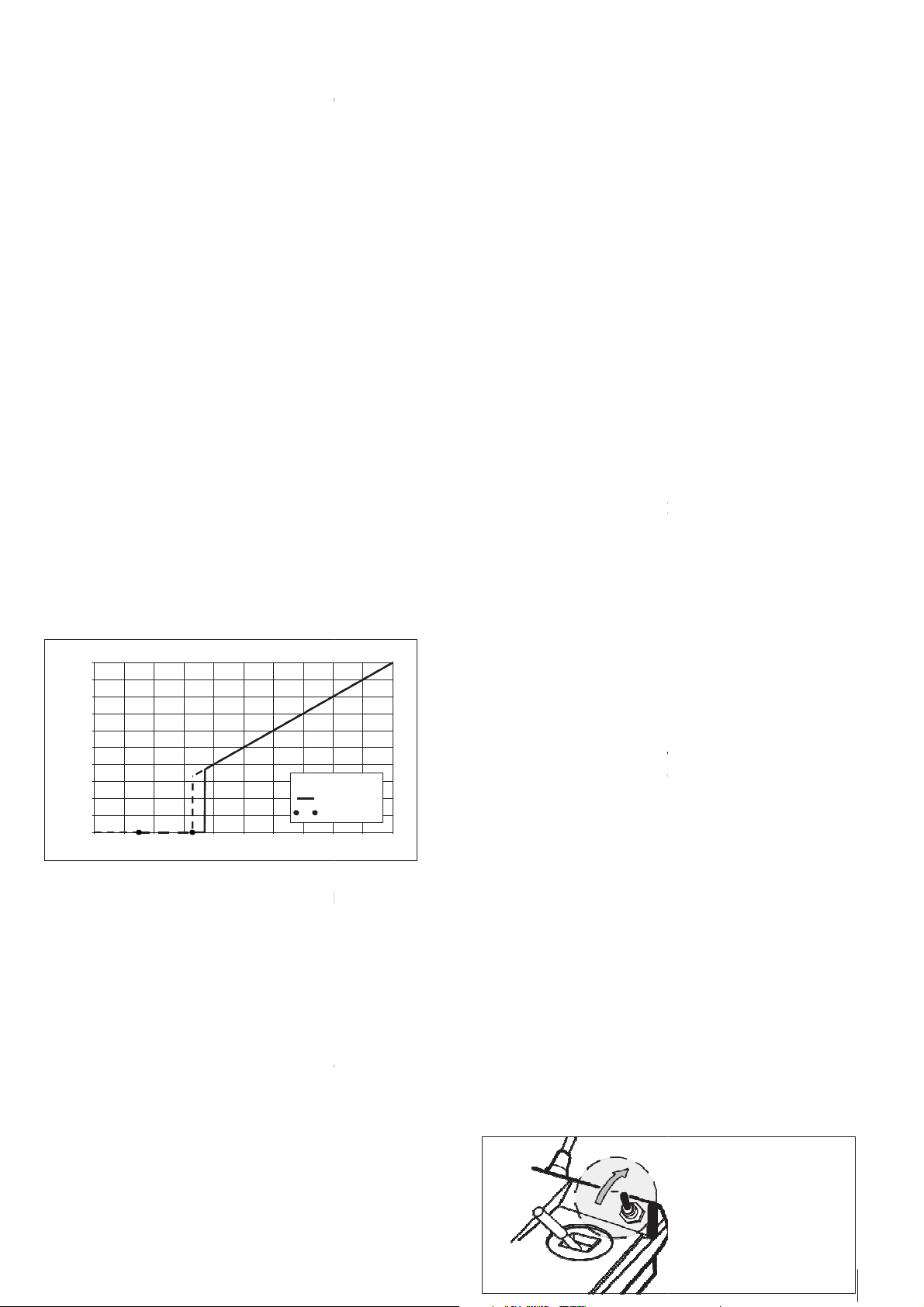
3.1
Gaskurve im Sender zur
V
o
r
b
e
r
e
i
tung
der R
eg
l
e
r
p
r
og
r
a
mm
i
e
r
un
g
Im Sender wird auf den für das Gas
f
e
s
t
g
e
l
e
g
ten
Kanal eine linear ansteigende Gasgerade von 0%
bis 100%
e
in
g
e
s
t
e
ll
t
.
Der Gaskanal kann wahlweise auf einen Knüppel,
Schalter, Schiebe- oder Drehregler gelegt
w
e
r
d
e
n.
3.2
Programmierung
des
ge
w
ün
s
c
h
t
e
n
Modus im R
eg
l
e
r
Beim Programmieren des gewünschten
Mo
dus
lernt der Regler den am Sender zur Verfügung
stehenden Gasweg ein
(
0
–
100
%
)
. Alle weiteren,
für den gewählten Modus n
o
t
w
e
ndigen Parameter
stellt der KOSMIK
a
u
t
o
m
a
tisch ein.
Für die Programmierung der Modi sind un
t
e
r
-
schiedliche Schritte notwendig. Die
V
o
r
g
e
hens-
weise entnehmen Sie bitte dem j
e
w
e
iligen Text in
dieser
A
nl
e
i
t
un
g
.
Bitte beachten Sie, Modus 1 bis 6 können
über die Modusprogrammierung, nicht über
die PROGDISC, progr
a
mm
i
e
r
t
werden.
3.3 S
a
n
f
t
a
n
l
a
u
f
Mittels Sanftanlauf erhöht der Regler inn
e
rhalb der
eingestellten Zeit die
Mo
t
o
r
d
r
e
h
za
hl. Die Zeit für
das Hochlaufen von 0% auf 100
%
kann über die
PROGDISC
zwischen 8 und 60 sek frei eingestellt
werden
(
De
f
a
ul
t
c
a
.12
Se
k
un
d
e
n
)
. Je höher der
festgelegte
P
r
o
zentsatz des Gaskanals am Sender
ist,
d
e
s
t
o
höher ist die eingeregelte Drehzahl.