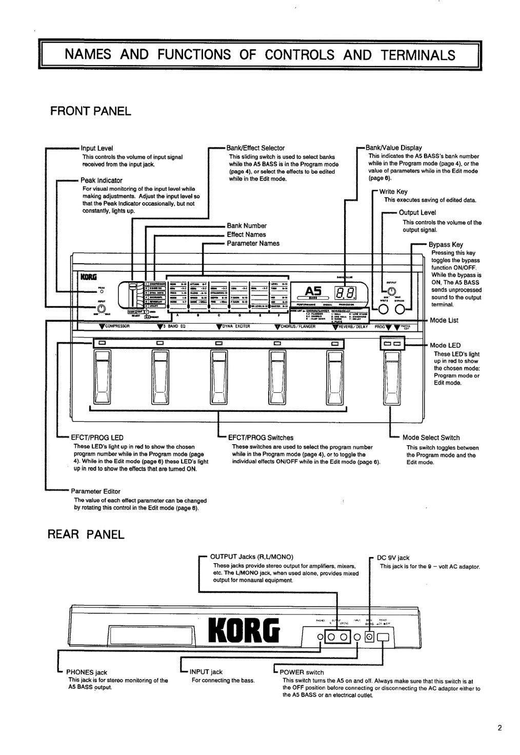
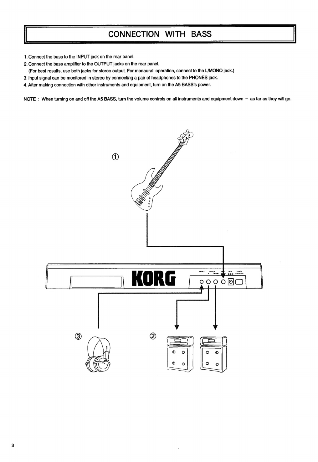
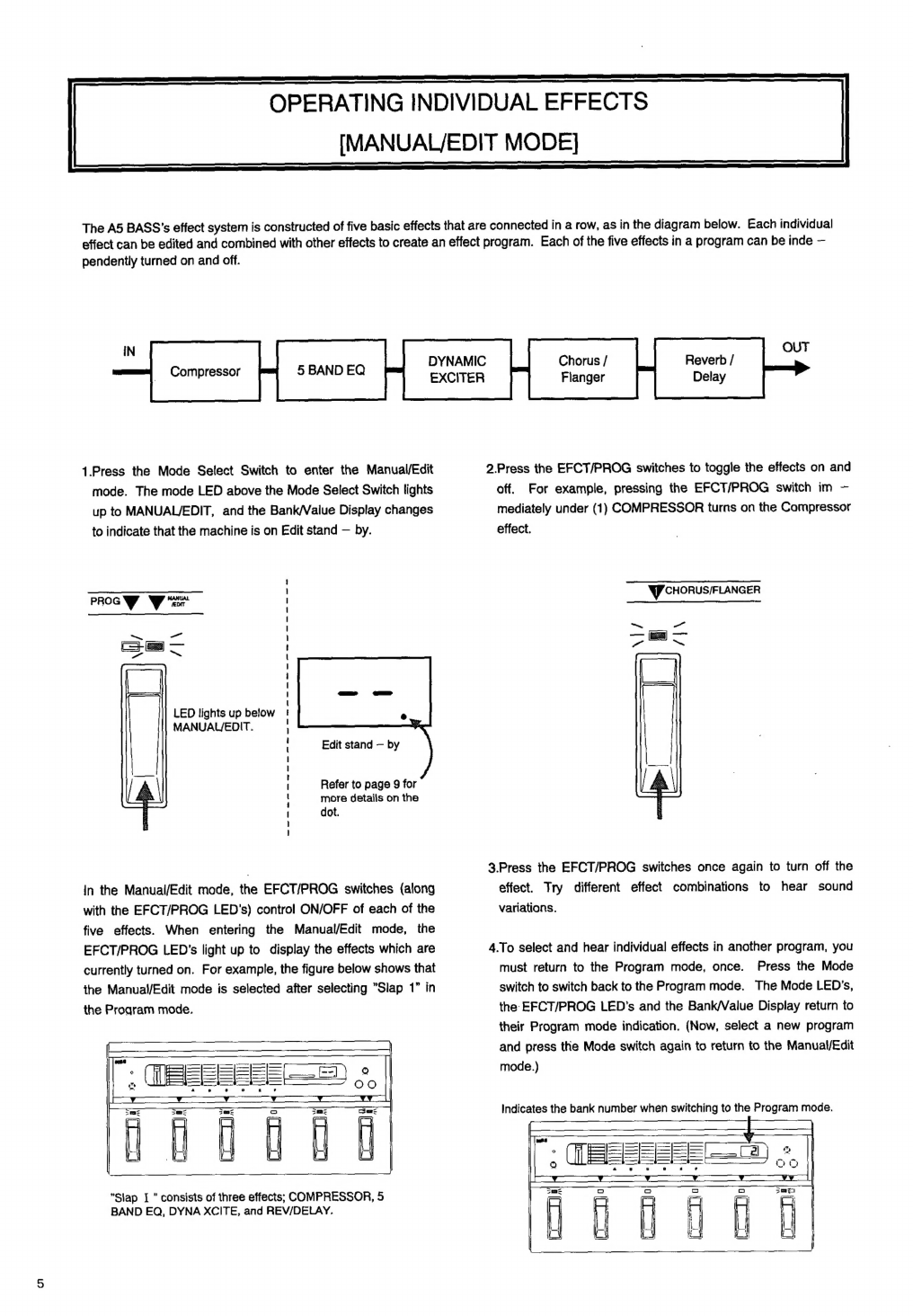
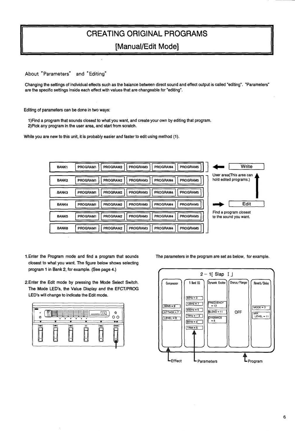
Korg A5 Guitar User manual
Other Korg Computer Hardware manuals

Korg
Korg EasyStart KAOSS PAD Entrancer User manual

Korg
Korg PA1X User manual

Korg
Korg EXBP-MP3 User manual

Korg
Korg EXB-PCM-03 User manual

Korg
Korg EXB-PCM04 User manual

Korg
Korg EasyStart PX24D Owner's manual

Korg
Korg AIB-8 User manual

Korg
Korg Toneworks AX3G User manual

Korg
Korg EXB-PCM05 User manual

Korg
Korg M3 User manual


Popular Computer Hardware manuals by other brands

EMC2
EMC2 VNX Series Hardware Information Guide

Panasonic
Panasonic DV0PM20105 Operation manual

Mitsubishi Electric
Mitsubishi Electric Q81BD-J61BT11 user manual

Gigabyte
Gigabyte B660M DS3H AX DDR4 user manual

Raidon
Raidon iT2300 Quick installation guide

National Instruments
National Instruments PXI-8186 user manual