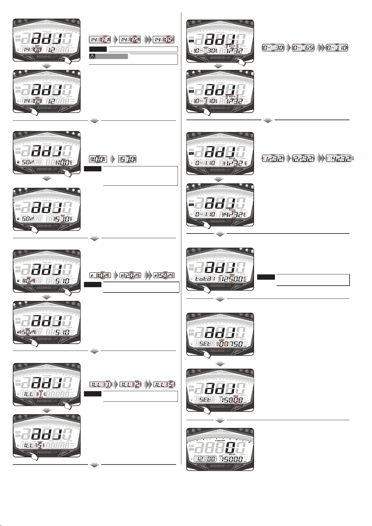
If you don't reach the target
speed or stop accelerating
during the test, press the
Adjust button to stop the
timer. Press the Adjust button
once to clear the record and
enter the target speed timer test screen.
Speed up
Test
failure
3 km/h0 km/h
During the test recording, the will ash!
When the bike moves, the timer will
start automatically.
About the power test
setting, please check (4-2)
0 km/h 3 km/h 110 km/h
5-1
5-2
Target speed timer test
WARNING!
In power test screen, press the Select button
once to enter the target speed timer
test screen.
Use this function at racetrack to avoid
trac accidents.
Please start the test while the
is not moving
If you already have a record, it will
display the record rst. You must clear
the record before starting a
new test.
Press the Adjust button to clear the
record and enter the target speed
timer test screen.
EX. You now see the previous
record. It is displaying the target
speed timer setting (0~110 km/h),
the test result (19”20 s), the top speed
(110 km/h) during the test and the
MAX RPM (10,000)
The record
display screen
To enter the
testing screen
To enter the thesting screen if there is no record
To enter the thesting screen if there is no record
The timer is automatic, so
moving the bike will start
the timer and stop when
your bike stops moving.
Speed up
Target distance timer test
WARNING!
Use this function at racetrack to avoid
trac accidents.
Please start the test while the
is not moving
If you already have a record, it will
display the record rst. You must clear
the record before starting a
new test.
In power test screen, press the Select
button 2 times to enter the target
distance timer test screen.
Press the Adjust button to clear the
record and enter the target distance
timer test screen.
EX. You now see the previous
record. It is displaying the target
speed timer setting (2/32 mile (100M)),
the test result (10”27 s), the top speed
(63 km/h) during the test and the
MAX RPM (8,000).
When the bike moves, the timer will
start automatically.
About the power test setting,
please check 4-2 .
The timer is automatic, so
moving the bike will start
the timer and will stop when
your bike stops moving.
Speed up
0 M100 m
If you want to test it again, press the Adjust
button to clear the record and enter the target
speed timer test screen again.
If you don't reach the target
speed or stop accelerating
during the test, press the
Adjust button to stop the
timer. Press the Adjust button
once to clear the record and
enter the target distance timer test screen.
Speed up
Test
failure0 M
●In main screen, press and hold the
Adjust button 3 seconds to enter the
target speed timer test setting.
●In main screen, press & hold the
Adjust button 3 seconds to enter the
target distance timer test setting.
If you just want to use the function once,press
& hold the Select button for 3 seconds to save
the records and back to the main screen.
If you just want to use the function once,press
& hold the Select button for 3 seconds to save
the records and back to the main screen.
When you reach the set target speed
(0~110 km/h), the timer will stop
counting (19”20 s) automatically.
When you reach the set target distance
(100 M . 2/32 mile), the timer will stop
counting (19”20 s) (10”27s)automatically.
If you want to test it again, press the
Adjust button to clear the record and
enter the target speed timer test
screen again.
If you just want to use the function once,press & hold
the Select button for 3 seconds to save the records
and back to the main screen.
If you just want to use the function once,press & hold
the Select button for 3 seconds to save the records
and back to the main screen.
wh022ba04d-5
NOTE
NOTE
NOTE
NOTE
P. S
P. S
P. S
P. S
TIME TIME TIME
TIME TIME TIME
TIME TIME TIME
During the test recording, the will ash!
The record
display screen
To enter the
testing screen