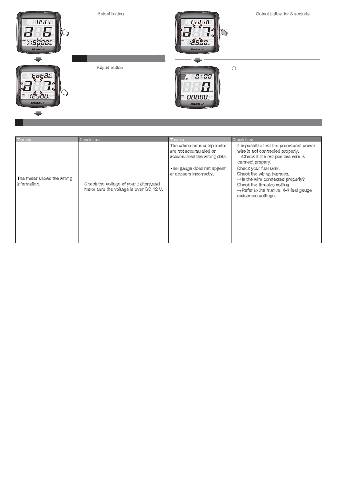
The reset value will depend on the setting
value according to 4-5 Maintenance
Mileage Setting.
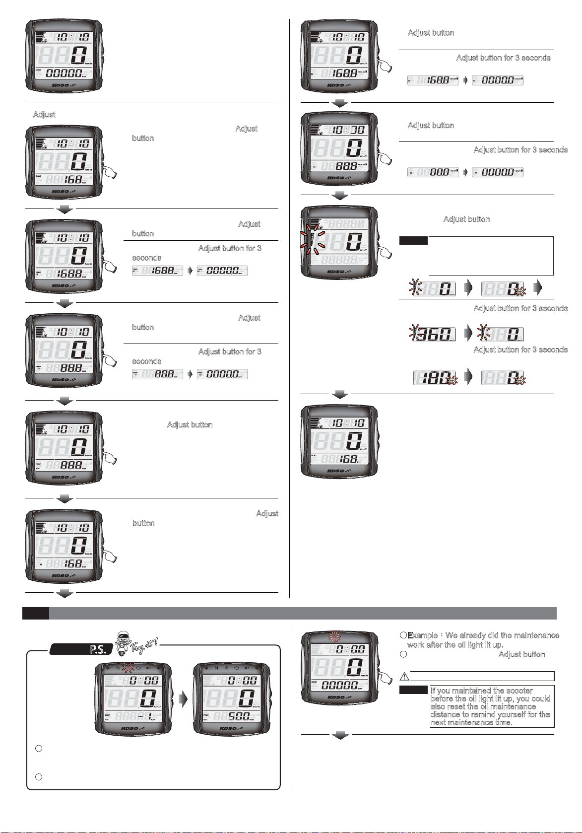
쀛Maintenance Mileage "Reset" screen.
쀛EX. The Maintenance Mileage to be reset
from -1 to setting value.
In Maintenance Mileage Reset screen,
press the Adjust button to give up the
reset and then warning light will back to
light on steady from flashing.
In Maintenance Mileage Reset screen, press
the Adjust button to give up the reset and
then warning light will back to light on steady
from flashing.
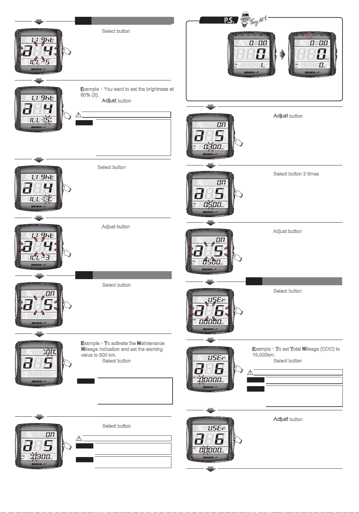
쀛Press the Adjust button for 3 seconds to
confirm the Maintenance Mileage to be
reset.
쀛In the oil maintenance mileage screen,
Press the Adjust button for 3 seconds to
enter the Maintenance Mileage "Reset"
screen .
NOTE
쀛
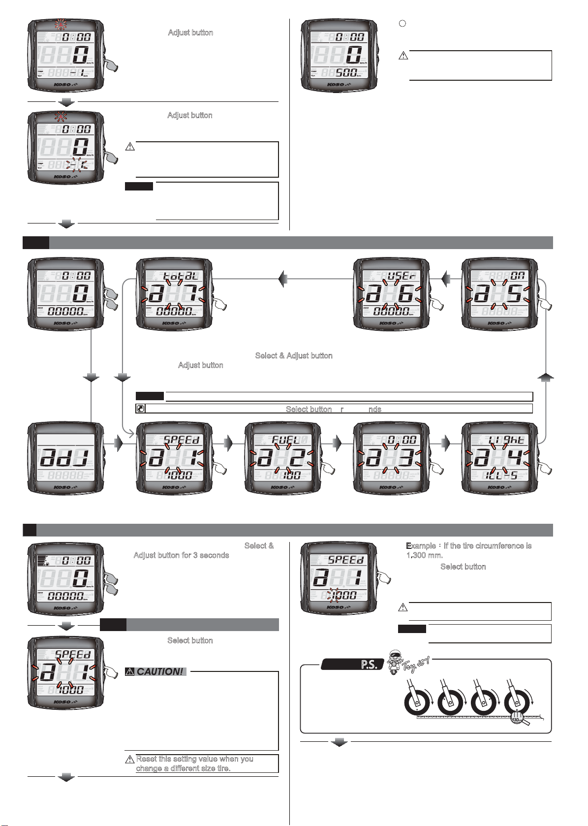
In main screen, press down the Select & Adjust button at the same time for 3 seconds to enter the setting screen.
쀛
Press the Adjust button to select in following order start fromCircumference and sensing point뺓Fuel gauge
resistance 섺뺓Clock setting뺓Backlight brightness setting뺓Oil maintenance mileage뺓Odometer뺓Internal
ODO display .
The screen will return to the main screen after 30 seconds if no button is press.
3-5
Setting screen instruction
쀛In main screen 쀛Internal ODO display 쀛Odometer 쀛Oil maintenance
mileage
NOTE
In any screen, you could hold down the Select button for 3 seconds to back to the main screen.
P.S.
쀛Circumference and
sensing point
쀛Setting screen 쀛Fuel gauge resistance 쀛Clock setting 쀛Backlight brightness
setting
4
Entering setting screen
쀛In main screen, press down the Select &
Adjust button for 3 seconds to enter the
setting screen.
쀛Press the Select button to enter the
circumference and sensing point setting
screen.
4-1
Circumference and sensing point
setting
Reset this setting value when you
change a different size tire.
NOTE
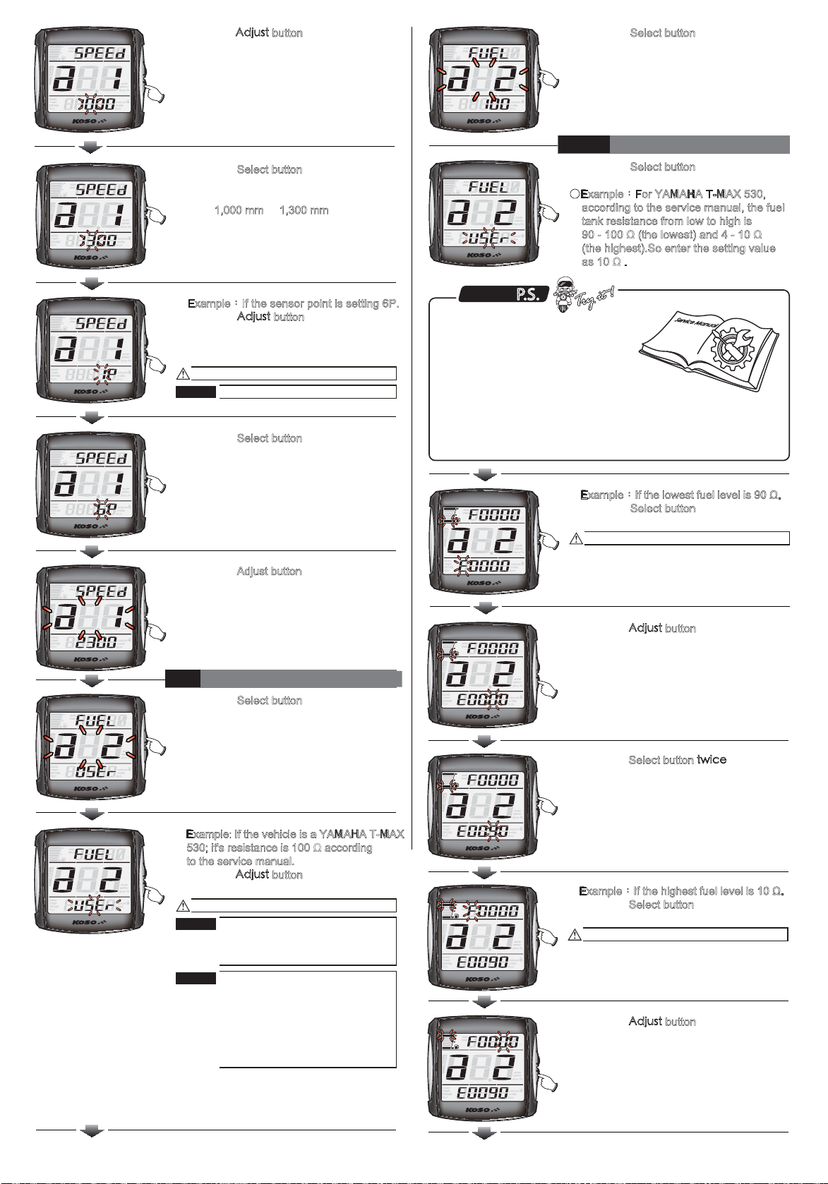
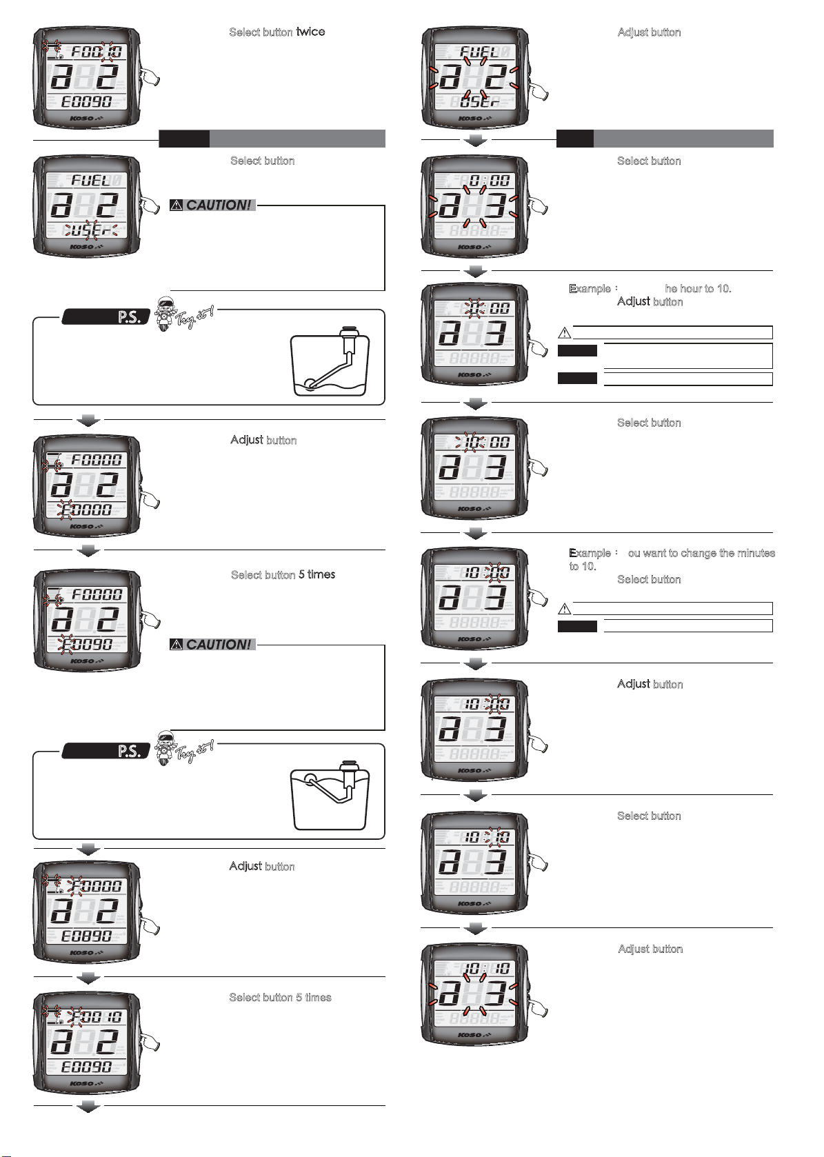
쀛Press the Select button to the digit you
want to set.
쀛Example:If the tire circumference is
1300 mm.
쀛EX. Now the tire circumference is setting
from 1000 mm.
Setting range:300 ~ 2500 mm
Setting unit:1 mm
Now the digit in thousands setting
number is flashing!
쀛You could define the
valve as the starting
point and the terminal
point to measure the
wheel circumference
with a measuring tape.
쀛Press the #FLWUV button to choose the
setting number.
쀛Measure the tire circumference
(The tire you will install the sensor on) and
make sure the number of magnet sensor
point (You could install the magnet into the
disc screw or the sprocket screw.)
쀛The speed displayed on the meter will be
affected by the setting, make sure
the setting number is correct before you
make the setting.
쀛Press the Select button to enter the sensor
point setting.
쀛EX. The circumference setting is changed
from 1,000 mm to 1,300 mm.
NOTE Sensitive point:1 ~ 6
Now the setting value is flashing!
쀛Press the Select button to go back to the
circumference and sensing point setting
screen.
쀛Ex. Now the sensor point is setting
from 1P to 6P.
4-2
Fuel gauge resistance settings
쀛Press the Select button to enter the
circumference and sensing point setting
screen.
쀛Press the Adjust button to select the fuel
gauge resistance setting screen.
쀛Example:If the sensor point is setting 6P.
쀛Press the #FLWUV button to choose the
setting number.
쀛Ex. Now the sensor point is setting
from 1P.
NOTE The fuel gauge resistance setting
range:USER뺓ȍ뺓ȍ뺓
ȍ뺓ȍ뺓ȍ뺓
SW (turn off)
NOTE
Now the setting value is flashing!
Custome fuel level resistance:
1) Manual - Please check 4-2-1
Fuel Level Resistance Manual
Setting Instructions.
2) Auto - Please check 4-2-2
Fuel Level Resistance Auto
Setting Instructions.
쀛Example: If the vehicle is a YAMAHA T-MAX
530; it's resistance is 100 ȍaccording
to the service manual.
쀛Press the #FLWUV button to choose the
setting number.
Now the setting value is flashing!
쀛Example:If the highest fuel level iVȍ.
쀛Press the Select button to the digit you
want to set.
쀛Press the #FLWUV button to choose the
setting number.
YJDDC
P.S.
4-2-1
Fuel Level Manual Setting
쀛Press the Select button to enter the lowest
fuel level's resistance setting screen.
쀛Example:For YAMAHA T-MAX 530,
according to the service manual, the fuel
tank resistance from low to high is
90 - 100 ȍ(the lowest) and 4 - 10 ȍ
(the highest).So enter the setting value
as 10 ȍ.
쀛Press the Select button to go back to the
circumference and sensing point setting
screen.
쀛Ex. Now the circumference and sensing
point setting IURP86(5WRȍ
쀛You could find your fuel level sensor
resistance range in the electronic
components section in the service
manual.
쀛Normally, we will recommend to
choose the closest number set as
the range to ensure that riders will not run out of gas before the fuel
level indication. example, for YAMAHA T-MAX it’s 90 - 100 ȍ
and 4 - 10 ȍ, in which case we will suggest to use 90 - 10 ȍas the
lowest and highest range.
Now the setting value is flashing!
쀛Example:If theORZHVWIXHOOHYHOLVȍ.
쀛Press the Select button to the digit you
want to set.
쀛Press the Select buttonVYKEGto enter in
the highest fuel level's resistance setting
screen.
쀛EX. The lowest fuel level setting is
changed from WRȍ
쀛Press the #FLWUV button to choose the
setting number.