KRAL CL Series User manual

Operating instructions
KRAL screw pumps.
Series CL
Magnetic coupling
Observe safety instructions for persons with cardiac pacemaker, metallic implant or
neurostimulator.
OIC 13en-GB
Edition 2020-02
Original instructions
www.kral.at

Table of contents
1 About this document ..................................................... 3
1.1 General information .......................................................3
1.2 Associated documents ..................................................3
1.3 Target groups ................................................................3
1.4 Symbols.........................................................................3
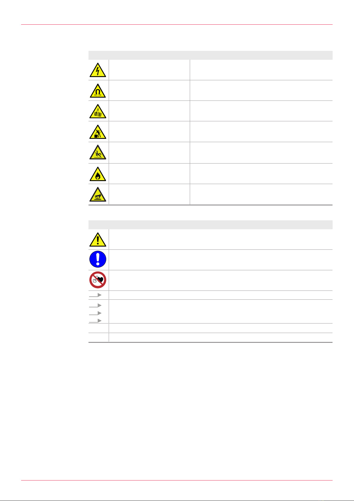
1.4.1 Danger levels ....................................................3
1.4.2 Danger signs.....................................................4
1.4.3 Symbols in this document .................................4
2 Safety .............................................................................. 4
2.1 Proper use .....................................................................4
2.2 Foreseeable misuse ......................................................5
2.3 Obligations of the operator-owner .................................5
2.4 Safety instructions .........................................................5
2.4.1 Fundamental safety instructions .......................5
2.4.2 Dangers at magnetic coupling systems ............5
3 Identification................................................................... 6
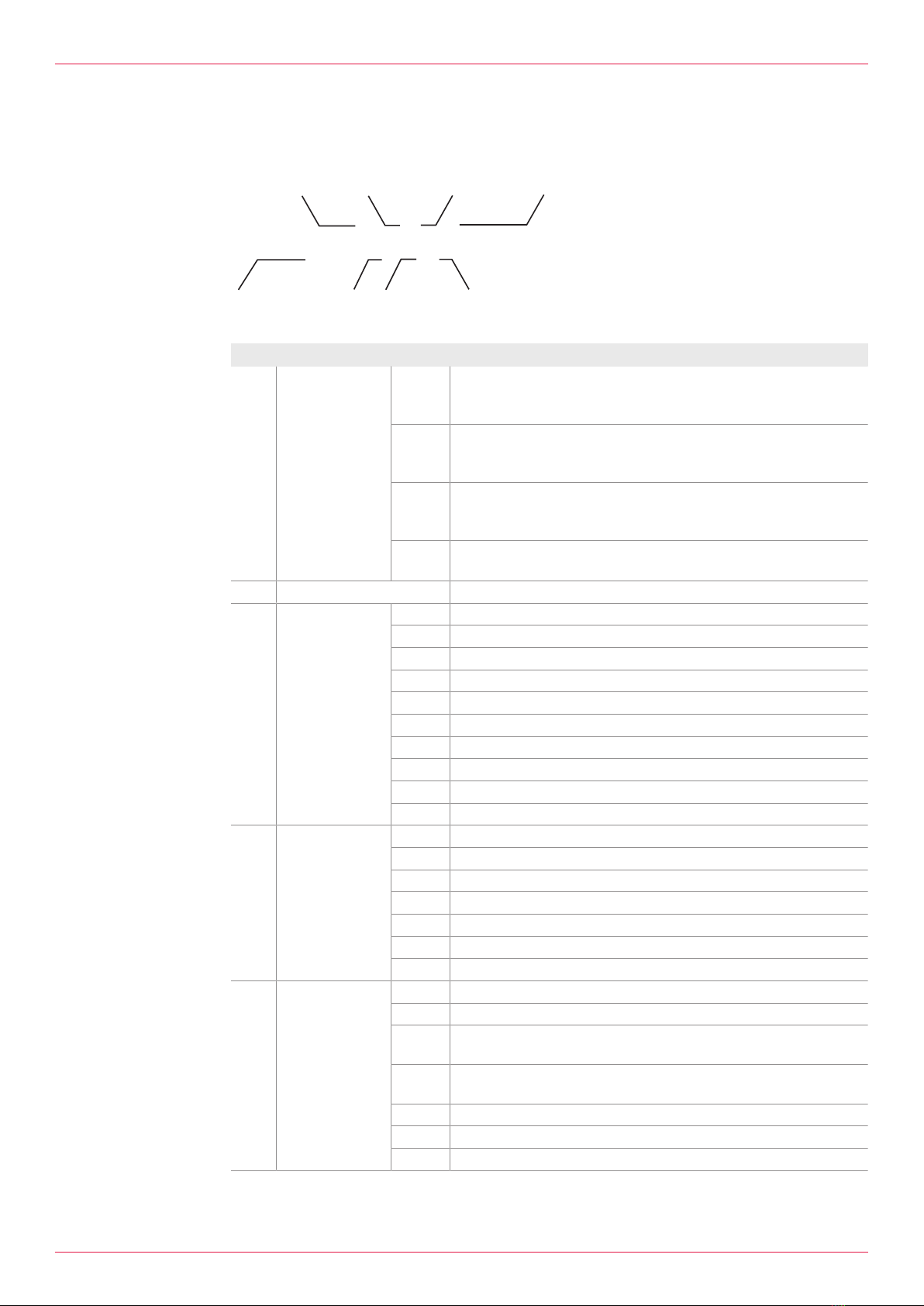
3.1 Type code......................................................................6
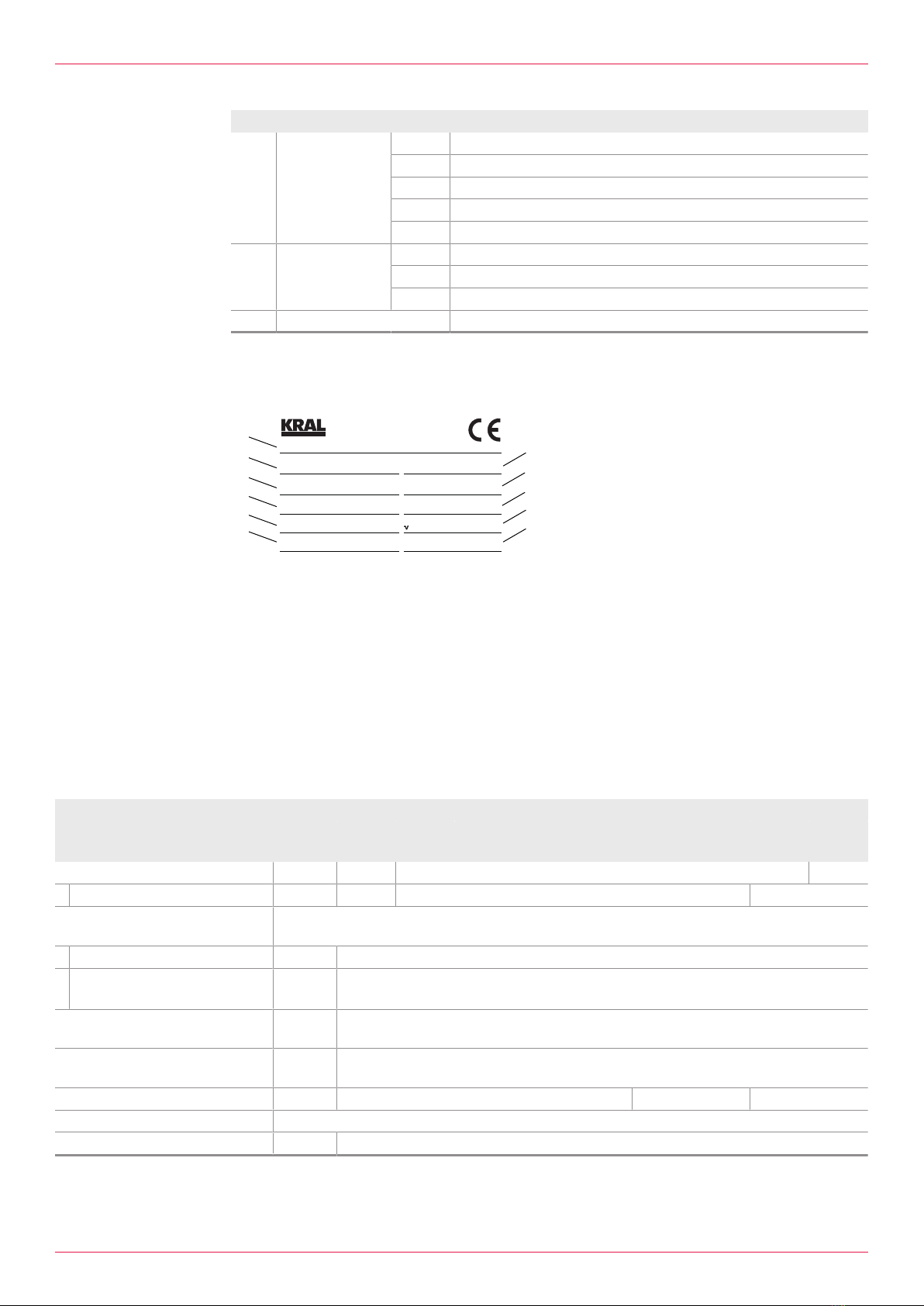
3.2 Rating plate ...................................................................7
4 Technical data ................................................................ 7
4.1 Operating limits..............................................................7
4.2 Required NPSH values..................................................8
4.3 Sound pressure level.....................................................8
4.4 Weights..........................................................................8
4.5 Accessories ...................................................................8
5 Function description...................................................... 8
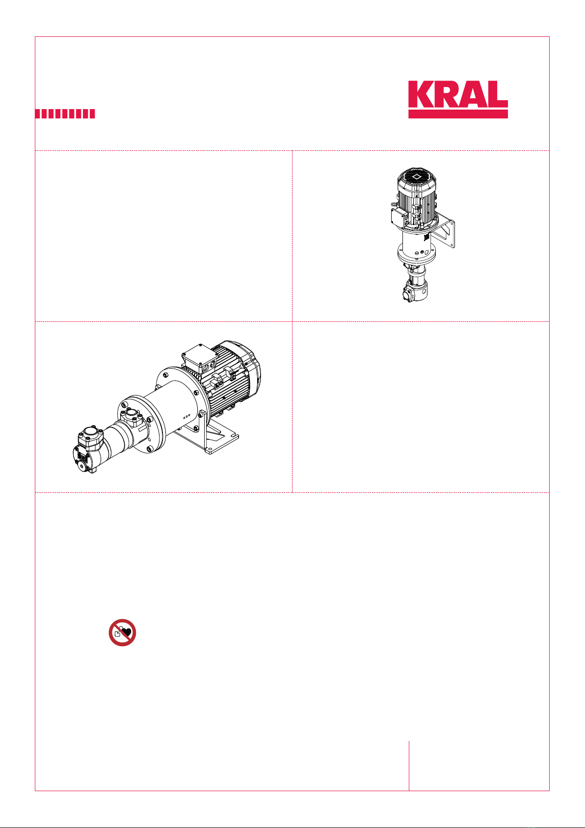
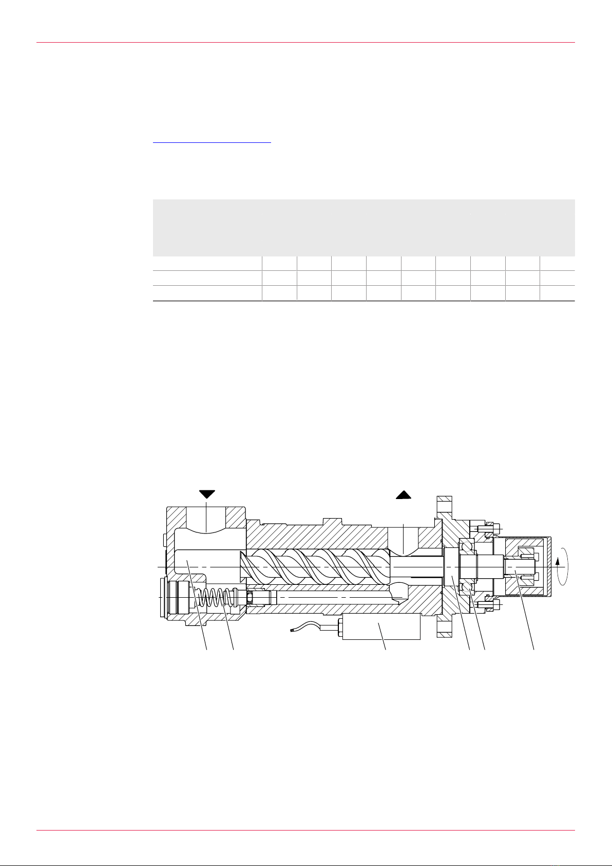
5.1 Pump structure ..............................................................8
5.2 Pump unit structure .......................................................9
5.3 Functional principle........................................................9
5.4 Magnetic coupling..........................................................9
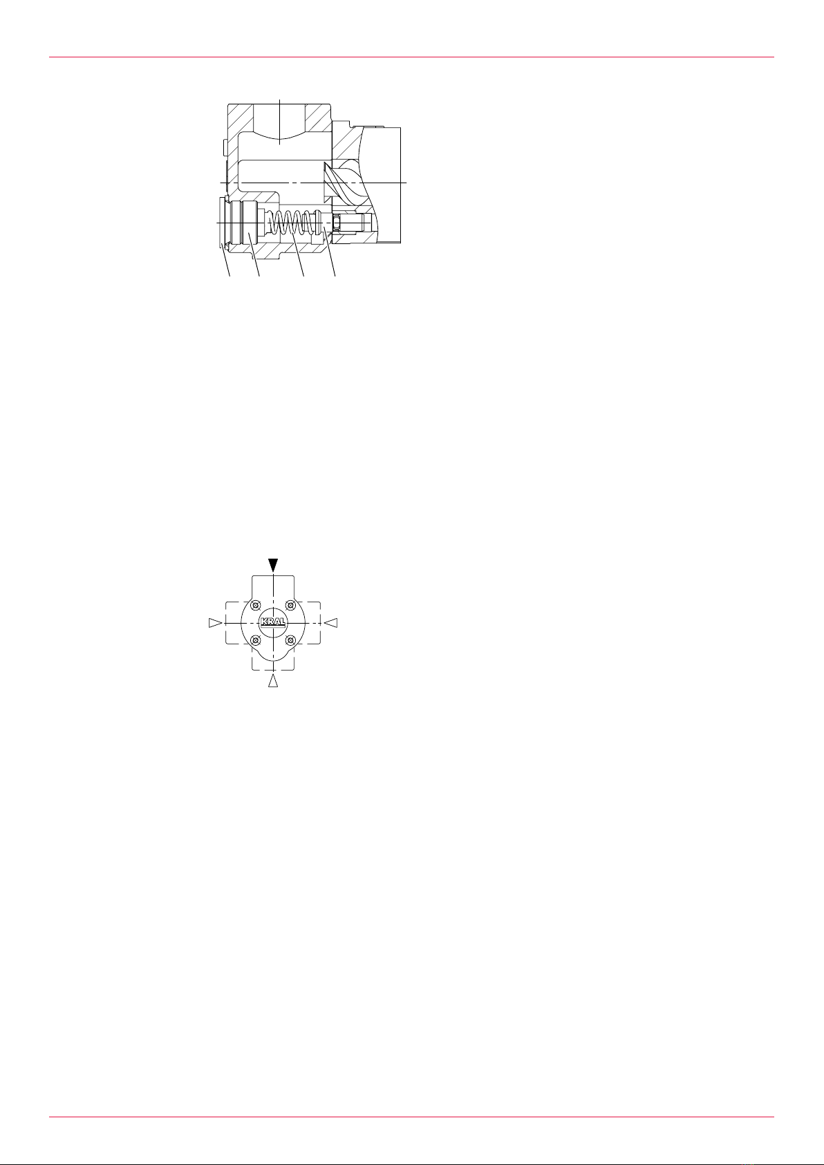
5.5 Overflow valve ...............................................................9
6 Transportation, storage............................................... 11
6.1 Dangers during transportation .....................................11
6.2 Dangers during storage ...............................................11
6.3 Unpacking and checking the state of delivery .............11
6.4 Transporting the pump/pump unit................................11
6.5 Storing the pump .........................................................12
7 Preservation ................................................................. 13
7.1 Preservation table........................................................13
7.2 Preserving the inner surfaces......................................13
7.3 Preserving the outer surfaces......................................13
7.4 Removing the preservation..........................................14
8 Installation, removal .................................................... 14
8.1 Dangers during installation ..........................................14
8.2 Dangers during removal ..............................................15
8.3 Installing the pump ......................................................15
8.4 Removing the pump ....................................................16
9 Connection ................................................................... 17
9.1 Dangers during connection work .................................17
9.2 Connecting the pump to the pipe system ....................17
9.3 Insulating the pump .....................................................18
9.4 Connecting the pump unit to the power supply ...........19
10 Operation ...................................................................... 19
10.1 Dangers during operation ............................................19
10.2 Commissioning ............................................................20
10.2.1 Cleaning the pipe system ................................20
10.2.2 Filling and venting the pump............................20
10.2.3 Checking the direction of rotation ....................21
10.2.4 Commissioning the pump ................................21
10.3 During operation ..........................................................23
10.3.1 Checking the operating pressure.....................23
10.3.2 Monitoring filters and/or strainers ....................23
10.3.3 Adjusting the overflow valve ............................24
10.3.4 Switching off the pump unit .............................24
10.4 Decommissioning.........................................................25
10.4.1 Decommissioning the pump ............................25
10.5 Recommissioning.........................................................26
10.5.1 Recommissioning the pump ............................26
11 Maintenance...................................................................26
11.1 Dangers during maintenance.......................................26
11.2 Required maintenance.................................................26
11.3 Ball bearing ..................................................................26
11.4 Maintaining the pump...................................................27
11.5 Maintaining the magnetic coupling...............................27
12 Servicing ........................................................................28
12.1 Dangers during servicing .............................................28
12.2 Wear ............................................................................29
12.2.1 Signs of wear...................................................29
12.2.2 Magnetic coupling............................................29
12.3 Replacing the magnetic coupling .................................29
12.3.1 Removing the outer rotor.................................29
12.3.2 Removing the inner rotor .................................30
12.3.3 Installing the inner rotor ...................................31
12.3.4 Installing the outer rotor...................................32
12.4 Replacing the ball bearing and screw set ....................33
12.4.1 Removing the ball bearing and screw set........33
12.4.2 Installing the ball bearing and screw set..........34
13 Disposal..........................................................................36
13.1 Dismantling and disposing of the pump ......................36
14 Troubleshooting ............................................................37
14.1 Possible faults..............................................................37
14.2 Troubleshooting ...........................................................37
15 Accessories ...................................................................39
15.1 Heating.........................................................................39
15.1.1 Possible types of heating.................................39
15.1.2 Electrical heating system.................................39
15.1.3 Fluid heating system........................................41
15.1.4 Heating system special design ........................43
16 Spare parts.....................................................................43
16.1 Overview ......................................................................43
16.2 Overflow valve .............................................................44
17 Appendix ........................................................................45
17.1 Tightening torques for screws with metric screw threads
with and without wedge lock washers..........................45
17.2 Tightening torques for screw plugs with thread meas-
ured in inches and elastomer seal ...............................45
17.3 Tightening torques for screws of tensioning elements
.....................................................................................46
17.4 Contents of the Declaration of Conformity ...................46
2OIC 13en-GB Edition 2020-02 Operating instructions

1 About this document
1.1 General information
1 About this document
1.1 General information
These instructions form part of the product and must be kept for future reference. Furthermore please
observe the associated documents.
1.2 Associated documents
oDeclaration of conformity according to EU Directive 2006/42/EC
oManufacturer's declaration according to EU Directive 2014/68/EU
oData sheet of the pump
oTechnical documentation of the supplied components
1.3 Target groups
The instructions are intended for the following persons:
oPersons who work with the product
oOperator-owners who are responsible for the use of the product
Persons who work with the product must be qualified. The qualification ensures that possible dangers
and damage to property that are connected to the activity are detected and avoided. These persons
are qualified personnel who carry out the work properly due to their training, knowledge and experience
and on the basis of the relevant provisions.
Information on the required qualification of the personnel is provided separately at the beginning of the
individual chapters in these instructions. The following table provides an overview.
Target group Activity Qualification
Transport
personnel
Transporting,
unloading,
setting up
Qualified personnel for transport, mobile crane operators, crane op-
erators, forklift operators
Fitter Mounting,
connection
Qualified personnel for mounting
Electrician Electrical
connection
Qualified personnel for electric installation
Trained
personnel
Delegated task Personnel trained by the operator-owner who know the task
delegated to them and the possible dangers arising through
improper behaviour.
Tab.1: Target groups
1.4 Symbols
1.4.1 Danger levels
Signal word Danger level Consequences of non-observance
DANGER Immediate threat of danger Serious personal injury, death
WARNING Possible threat of danger Serious personal injury, invalidity
CAUTION Potentially dangerous situation Slight personal injury
ATTENTION Potentially dangerous situation Material damage
Operating instructions OIC 13en-GB Edition 2020-02 3

2 Safety
2.1 Proper use
1.4.2 Danger signs
Meaning Source and possible consequences of non-observance
Electrical voltage Electrical voltage causes serious physical injury or death.
Magnetic field Magnetic field can cause serious physical injury or death.
Raised load Falling objects can result in serious physical injury or death.
kg
Heavy load Heavy loads can result in serious back problems.
Risk of slipping Discharging pumped liquid and oils on the foundation or
tread surfaces can cause falls with serious physical injury
or death.
Flammable substances Discharging pumped liquid and oils can be easily inflam-
mable and can result in serious burns.
Hot surface Hot surfaces of the pump unit can cause burns.
1.4.3 Symbols in this document
Meaning
Warning personal injury
Safety instruction
Prohibition sign cardiac pacemaker
Request for action
1.
2.
3.
Multi-step instructions for actions
Action result
Cross-reference
2 Safety
2.1 Proper use
oUse the pump solely for transporting lubricating liquids that are chemically neutral and that do not
contain gas or solid components.
oUse the pump only within the operating limits specified on the rating plate and in the chapter "Tech-
nical data". In the case of operating data that do not agree with the specifications on the rating
plate, please contact the manufacturer.
oThe pump is designed specially for the operating pressure named by the customer. If the actual op-
erating pressure deviates notably from this design pressure, damage to the pump can also arise
within the specified operating limits. This applies both to notably higher as well as to notably lower
operating pressures. Under no circumstances may the minimum pressure lie below 2bar. In case
of any doubt, please contact the manufacturer.
4OIC 13en-GB Edition 2020-02 Operating instructions

2 Safety
2.2 Foreseeable misuse
oAny use that extends beyond the proper use or any other use is misuse.
oThe product is not suitable for pumping liquids outside the operational limits.
oAny bypassing or deactivation of safety equipment during operation is prohibited.
2.3 Obligations of the operator-owner
The operator-owner is the person who operates the product commercially or permits a third party to
use it and who bears the legal responsibility for the product, the protection of the personnel and third
parties during its operation.
The product is used in industrial applications. The operator-owner is therefore subject to the statutory
obligations concerning occupational health and safety.
In addition to the safety instructions in these instructions, the regulations on safety, accident prevention
and environmental protection respectively valid for the range of application of the product are to be ob-
served.
2.4 Safety instructions
2.4.1 Fundamental safety instructions
The following safety instructions must be observed strictly:
oRead these operating instructions carefully and observe them.
oRead the operating instructions of the components carefully and observe them.
oHave work only carried out by qualified personnel/trained personnel.
oWear personal protective equipment and work carefully.
oPumped liquids can be subject to high pressure and can result in personal injury and damage to
property in case of incorrect operation or damaged components.
oPumped liquids can be hot, poisonous, combustible and caustic. Use corresponding protective
equipment.
oObserve the associated data sheets and safety regulations when handling dangerous materials.
oAvoid skin contact with system parts carrying liquids at operating temperatures exceeding 60°C.
oCollect any discharging pumped liquid safely and dispose of it in an environmentally compatible
manner in accordance with the applicable local regulations. Neutralize residues.
oKeep the mounting surfaces, scaffolding, ladders, lifting platforms and tools clean in order to pre-
vent slipping or stumbling.
oIf pressurized or energized components are damaged, shut down the pump immediately. Replace
the components or pump.
2.4.2 Dangers at magnetic coupling systems
Magnetic fields from magnetic coupling systems (MCS) can influence the function and operational
safety of electrical and electronic devices. The following safety instructions must be observed.
The following safety instructions must be observed:
oKeep the MCS away from cardiac pacemakers. There is a danger to life!
§Under no circumstances may persons with cardiac pacemakers perform installation, dismantling
or maintenance work.
oPersons with cardiac pacemakers must comply with the following safe distances to the MCS:
§3 m distance to the openly accessible MCS
§1 m distance to pump units with installed MCS
oDo not bring the MCS in the immediate area of PCs, data carriers and other electronic compon-
ents.
oKeep the MCS away from clocks, magnetized tools and measuring equipment as well as all mag-
netizable parts.
oDo not bring both the MCS parts together, as this can destroy the magnetic coupling system.
Operating instructions OIC 13en-GB Edition 2020-02 5

3 Identification
3.1 Type code
3 Identification
3.1 Type code
CLC-210.DZAAP.00021
1
2
3
4
7
8
5
6
Fig.1: Typenschlüssel
Item Classification Description
1Type CLC oPump with free shaft end
oPump unit with flanges, small flange
oPump unit with or without pump bracket foot
CLF oPump with free shaft end
oPump unit with flanges, large flange
oPump unit with or without pump bracket foot
CLH oPump with free shaft end with foot
oPump unit with base frame for horizontal mounting
oSmall flange
CLL oPump with free shaft end
oPump unit with flanges, large flange with pressure housing
2Size Corresponds to delivery rate in[l/min] at 1450min-1
3Shaft seal A Standard mechanical seal
B Mechanical seal of hard material
C Standard radial shaft seal
D Magnetic coupling
E Mechanical seal with quench
F Shaft seal PTFE with quench
G High-temperature radial shaft seal
H Mechanical seal balanced
J Stuffing box packing
X Special design
4Pressure stage
overflow valve
A Pressure stage 0.0–9.9bar
B Pressure stage 10.0–19.9bar
C Pressure stage 20.0–29.9bar
D Pressure stage 30.0–39.9bar
E Pressure stage 40.0–55.0bar
Z Without overflow valve
X Special design
5Bearings, heating
system and
pump housing
material
A Inside bearing without heating system, pump housing Silafont
B External bearing without heating system, pump housing Silafont
C Inside bearing with electrical heating system, pump housing Sila-
font
D External bearing with electrical heating system, pump housing
Silafont
E Inside bearing with fluid heating system, pump housing Silafont
F External bearing with fluid heating system, pump housing Silafont
X Special design
6OIC 13en-GB Edition 2020-02 Operating instructions

4 Technical data
3.2 Rating plate
Item Classification Description
6 Suction-side ac-
cessories
A Suction housing
B Suction filter
C Connection for suction pipe
Z Without accessories
X Special design
7Completion P Pump with free shaft end
K Pump with completion (without motor)
F Pump unit with completion
8 Version index For internal administration
Tab.2: Type code
3.2 Rating plate
KRAL GmbH, 6890 Lustenau, Austria www.kral.at
pSmax. / pDmax.
Ty p |Type
SN | Serial no.
Tmin. / Tmax. ºC
l/min
mm²/s
kg
min-¹
bar
bar
∆p
Jahr |Year Gewicht | Weight
n
Q
Art.-Nr. | Item no.
1
2
3
5
4
10
7
9
8
6
11
Fig.2: Rating plate
1Construction year
2Max. operating overpressure
suction-side /
Max. operating overpressure
pressure-side
3Temperature range
4Serial number
5Type
6Article number
7Differential pressure
8Nominal delivery rate
9Rated speed
10 Nominal viscosity
11 Weight
4 Technical data
4.1 Operating limits
Size
Parameter Unit 5–
10
15–
26
32–
42
55–
85
105–
118
160–
210
235–
275
370–
450
550–
880
Max. operating overpressure [bar] 100 70 40
oWith pressure housing [bar] – 100 80
Max. temperature of the
pumped liquid
oStandard magnetic coupling [°C] 180
oHigh-temperature magnetic
coupling
[°C] 250
Min. temperature for pump
materials
[°C] -10
Min.–max.
ambient temperature
[°C] -20...+50
Viscosity min.–max. [mm2/s] 4–5000 4–3000 4–2000
Speed max. Depending on viscosity, suction head/NPSH value and size
Max. inlet pressure [bar] Up to 16
Tab.3: Operating limits
Operating instructions OIC 13en-GB Edition 2020-02 7

5 Function description
4.2 Required NPSH values
The required NPSH values of the pump depend on the size, the viscosity of the pumped liquid and the
speed.
The NPSH values are available on the website of the manufacturer:
www.kral.at/en/screw-pumps
4.3 Sound pressure level
Guide values at 1 m distance, 1450 min-1, 20 bar, 21 mm2/s
Size
5–
10
15–
26
32–
42
55–
85
105–
118
160–
210
235–
275
370–
450
550–
880
Max. sound pressure level ±3[dB(A)]
Pump 53.0 57.0 59.0 63.0 65.0 69.0 71.0 74.0 80.5
Motor 52.0 59.0 63.0 65.0 67.0 67.0 73.0 73.0 75.0
Pump unit 55.5 61.0 64.5 67.0 69.0 71.0 75.0 76.5 82.0
Tab.4: Sound pressure level
4.4 Weights
The weight is specified on the rating plate.
4.5 Accessories
Notice The technical data of the accessories are specified separately Ä Accessories,Page39.
5 Function description
5.1 Pump structure
21 3 4 56
A A
B
Fig.3: Pump structure
1Suction housing (accessories) 5Main screw
2Overflow valve (integrated) 6Heating (accessories)
3Balancing cylinder AFlow direction
4Ball bearing BDirection of rotation
8OIC 13en-GB Edition 2020-02 Operating instructions

5 Function description
5.2 Pump unit structure
7 8 9 10 11
Fig.4: Pump unit structure
7Pump 10 Outer rotor
8Containment can 11 Motor
9Inner rotor
5.3 Functional principle
Screw pumps are rotating displacement pumps. Their displacement effect results from three rotating
screws and the enclosing pump housing.
Radial support of the screw set is effected through the sliding contact in the pump housing that de-
pends on lubrication by the pumped liquid. Screw pumps are therefore not suitable for dry running and
can only be used up to specific pressure limits and viscosity limits. Due to the narrow tolerances pump-
ing of suspended solids is not possible.
Axial support of the main screw is effected by a deep-groove ball bearing 4. In order to reduce the
pressure, a balancing cylinder3 is mounted at the main screw5. An integrated overflow valve2 pro-
tects against excessive pressure that could cause housing parts to burst.
The default direction of the rotationB of the screw set is clockwise viewed from the motor and is
marked on the pump flange by an arrow.
The flow directionA is marked on the pump housing by two arrows.
5.4 Magnetic coupling
The shaft end of the pump7 is enclosed by a containment can8 that is connected air-tight with the mo-
tor-side flange of the pump. Therefore, it is not necessary to seal a rotating free shaft end against a
stationary seal housing. Special rotors equipped with powerful permanent magnets are used for trans-
fer of torque from the motor to the pump. The inner rotor9 is fixed at the shaft end and driven by the
outer rotor10, which in turn is fixed to the shaft of the motor11. The torque is thus transferred contact-
free by means of the magnetic field between the outer and inner rotor.
The containment is made of a non-magnetic stainless steel which does not impede the forming of mag-
netic flux lines between the rotors. The pressure discharge of the containment can occur via a core
drilled hole in the main screw. Therefore, it can be assumed that the pressure in the containment can
approximately corresponds to the pressure on the suction side of the pump.
5.5 Overflow valve
Notice oThe protection of the pump must be ensured either through an integrated overflow valve or through
an overflow valve/safety valve installed on the system side.
oObserve the associated operating instructions and dimensioning sheet of the pump to set an over-
flow valve/safety valve installed on the system side.
Notice oA function test of the overflow valve at least every 5 years is essential for the safe operation Ä Dur-
ing operation,Page23.
oScope and if necessary shorter test intervals must be specified by the operator-owner in accord-
ance with the requirements and national provisions (for example Austrian Ordinance of Safety and
Health (BetrSichV)).
oThe first function test must take place directly after the commissioning.
oAfter longer downtimes (> 4 weeks) the function of the overflow valve must be tested again.
Operating instructions OIC 13en-GB Edition 2020-02 9

5 Function description
5.5 Overflow valve
1 2 43
Fig.5: Overflow valve, integrated
1Screw plug
2Adjusting screw
3Pressure spring
4Valve body
The overflow valve ensures that very high pressures that could result in housing parts bursting do not
arise.
The overflow valve is purely there as a safety element for the pump and should not be used for control
or regulation purposes such as maintaining pressure. If the valve is kept open for too long under ad-
verse operating conditions (high differential pressures and/or low viscosities) it will only take a few
minutes for the overflow valve and the valve seating to become damaged. As a result, the overflow
valve will leak permanently and there will be a corresponding reduction in the delivery rate. In addition
to this, circulation through the overflow valve for too long results in excess heating of the pump. This
reduces viscosity and can ultimately lead to pump failure.
It therefore has to be ensured through a safety valve at the system that the maximum operating pres-
sure always lies under the opening pressure of the overflow valve.
Notice The opening pressure of the overflow valve is set to 110% of the differential pressure in the factory.
The overflow valve is accessible through a screw plug1 and can be adjusted from the outside Ä Dur-
ing operation,Page23.
Notice At pumps without integrated overflow valve the suction housing can be mounted with a respective rota-
tion of 90°.
10 OIC 13en-GB Edition 2020-02 Operating instructions

6 Transportation, storage
6.1 Dangers during transportation
6 Transportation, storage
6.1 Dangers during transportation
The following safety instructions must be observed:
oHave all work only carried out by authorized transport personnel.
oUse intact and correctly dimensioned hoisting equipment.
oEnsure that the means of transport is in a flawless state.
oEnsure that the centre of gravity of the load is taken into consideration.
oDo not stand under raised loads.
6.2 Dangers during storage
The following safety instructions must be observed:
oObserve the storage conditions.
6.3 Unpacking and checking the state of delivery
Personnel qualification: oTrained personnel
1. Upon delivery check the pump/pump unit for damage during transportation.
2. Report damage during transportation immediately to the manufacturer.
3. Dispose of packaging material in accordance with the locally applicable regulations.
6.4 Transporting the pump/pump unit
Personnel qualification: oTransport personnel
Personal protective equipment: oWork clothing
oProtective helmet
oProtective gloves
oSafety boots
Aids: oMobile crane, forklift, hoisting equipment
DANGER
Magnetic field.
Risk of death for persons with cardiac pacemaker, metallic implant or neurostimulator.
► Under no circumstances may persons with cardiac pacemakers, metallic implant or neurostimu-
lator perform work on the pump/pump unit.
WARNING
Risk of injury and damage to equipment through falling and toppling parts.
► Use intact and correctly dimensioned hoisting equipment in accordance with the total weight to be
transported.
► Select the lift points for the hoisting equipment in accordance with the centre of gravity and the
weight distribution.
► Use at least two load ropes.
► In the case of vertical transportation secure the motor against tippling.
► Do not stand under raised loads.
ATTENTION
Damage to equipment through improper transportation.
► Protect the pump against damage, heat, sunlight, dust and moisture.
Operating instructions OIC 13en-GB Edition 2020-02 11

6 Transportation, storage
6.5 Storing the pump
Fig.6: Fastening of hoisting equipment - principle diagrams
1. Attach the hoisting equipment to the pump/pump unit and tighten. Ensure that the centre of grav-
ity lies exactly under the crane hook.
2. Lift the pump/pump unit carefully and put it down shock-free.
3. Before loosening the transport belts ensure that the pump/pump unit is secured against tilting.
6.5 Storing the pump
During the test run, the internal components of the pump are wetted with test oil, which has a preser-
vative effect. Pressure connection and suction connection are closed with protective caps. Unless oth-
erwise specified, the outer surfaces of the pump are preserved with a single-coat PU-based two-com-
ponent paint.
The preservative applied at the factory will protect the pump for about six weeks, if it is stored in a dry
and clean location.
The manufacturer offers a long-term preservation for storage times of up to 60months. The pump is
additionally packed in hermetically sealing anti-corrosion paper.
Personnel qualification: oTransport personnel
Aids: oMobile crane, forklift, hoisting equipment
DANGER
Magnetic field.
Risk of death for persons with cardiac pacemaker, metallic implant or neurostimulator.
► Under no circumstances may persons with cardiac pacemakers, metallic implant or neurostimu-
lator perform work on the pump/pump unit.
ATTENTION
Damage to equipment and corrosion if stored improperly and during longer standstills.
► Protect the pump against damage, heat, sunlight, dust and moisture.
► Protect against corrosion during longer standstill.
► Observe measures for storing and preservation.
1. Store cool and dry and protect against sunlight.
2. Ensure that the anti-corrosion paper is not damaged.
3. Observe the intervals for preservation Ä Preservation,Page13.
12 OIC 13en-GB Edition 2020-02 Operating instructions

7 Preservation
7.1 Preservation table
7 Preservation
7.1 Preservation table
Preservation has to be carried out additionally under the following conditions:
Type of delivery Condition
Standard delivery oStorage time exceeding six weeks
oUnfavourable storage conditions such as high humidity,
salty air, etc.
Delivery with long-term preservation oOpened or damaged packaging
Tab.5: Conditions for additional preservation
7.2 Preserving the inner surfaces
Personnel qualification: oTrained personnel
Personal protective equipment: oWork clothing
oProtective gloves
oSafety boots
Aids: oPreservative (acid-free and resin-free oil)
DANGER
Magnetic field.
Risk of death for persons with cardiac pacemaker, metallic implant or neurostimulator.
► Under no circumstances may persons with cardiac pacemakers, metallic implant or neurostimu-
lator perform work on the pump/pump unit.
1. Open the packaging carefully. If the pump is protected additionally by anti-corrosion paper, en-
sure that it is not damaged.
2. Close the suction connection of the pump with a blind flange.
3. Pour the preservative into the pressure connection until it reaches approx.2cm under the rim,
while slowly turning the main screw against the direction of rotation.
4. Close the pressure connection of the pump with a new blind flange.
5. Close the packaging carefully.
6. After about six months storage check the filling level of the preservative and if necessary top up.
7.3 Preserving the outer surfaces
Personnel qualification: oTrained personnel
Personal protective equipment: oWork clothing
oFace protection
oProtective gloves
oSafety boots
Aids: oCalcium complex grease (for example TEVI-
ER®GREASEWAWE100 with adhesive additive)
oCastrol Rustilo DWX 33 or other preservative offering compar-
able protection
DANGER
Magnetic field.
Risk of death for persons with cardiac pacemaker, metallic implant or neurostimulator.
► Under no circumstances may persons with cardiac pacemakers, metallic implant or neurostimu-
lator perform work on the pump/pump unit.
Operating instructions OIC 13en-GB Edition 2020-02 13

8 Installation, removal
7.4 Removing the preservation
1. Brush calcium complex grease corrosion protection (for example TEVIER® FETT WAWE 100
with adhesive additive) to the mounting surfaces.
2. Brush or spray preservative (for example Castrol Rustilo DWX 33) onto the process connections
and remaining plain and unpainted parts.
3. At intervals of about six months check the preservation and if necessary repeat.
7.4 Removing the preservation
Personnel qualification: oTrained personnel
Personal protective equipment: oWork clothing
oFace protection
oProtective gloves
oSafety boots
Aids: oSolvent
oCollection tank
oSteam-jet cleaning device with wax-dissolving additives
DANGER
Magnetic field.
Risk of death for persons with cardiac pacemaker, metallic implant or neurostimulator.
► Under no circumstances may persons with cardiac pacemakers, metallic implant or neurostimu-
lator perform work on the pump/pump unit.
CAUTION
Risk of injury through emitted preservative.
► Wear personal protective clothing during all the work.
► Collect any discharging preservative safely and dispose of it in an environmentally compatible
manner in accordance with the applicable local regulations.
1. Clean the outside of the pump with solvents, if necessary using a steam-jet cleaning device.
2. Remove the pressure-side blind flange carefully in order to reduce any pressure that may exist in
the pump.
3. Drain the pump, collecting the preservative in a suitable vessel.
4. Remove the blind flange on the suction side.
5. To remove the residual preservative, flush the pump with the pumped liquid.
8 Installation, removal
8.1 Dangers during installation
The following safety instructions must be observed strictly:
oHave all work carried out only by authorized qualified personnel.
oBefore installation ensure that the operating limits, NPSH values and ambient conditions are ob-
served.
oObserve the tightening torques Ä Appendix,Page45.
oEnsure that all the components can be accessed and that maintenance work can be carried out
easily.
14 OIC 13en-GB Edition 2020-02 Operating instructions

8 Installation, removal
8.2 Dangers during removal
The following safety instructions must be observed strictly:
oHave all work carried out only by authorized qualified personnel.
oBefore beginning work, let the pump unit cool down to the ambient temperature.
oCollect any discharging pumped liquid safely and dispose of it in an environmentally compatible
manner in accordance with the applicable local regulations.
oEnsure that the collection tank for discharging pumped liquids is sufficiently large.
8.3 Installing the pump
The pumps can be operated in horizontal and vertical installation position.
Notice Soiling in the pipe system impair the service life of the pump. If the pipe system is flushed using the
pump during the initial commissioning, an additional commissioning filter has to be installed temporarily
before the pump at the system (mesh width: 0.02mm).
Personnel qualification: oTransport personnel
oFitter
Personal protective equipment: oWork clothing
oProtective helmet
oProtective gloves
oSafety boots
Aids: oMobile crane, forklift, hoisting equipment
DANGER
Magnetic field.
Risk of death for persons with cardiac pacemaker, metallic implant or neurostimulator.
► Under no circumstances may persons with cardiac pacemakers, metallic implant or neurostimu-
lator perform work on the pump/pump unit.
WARNING
Risk of injury and damage to equipment through falling and toppling parts.
► Only fasten the pump on a stable load-bearing underground or stable load-bearing load support.
► Ensure that fastening elements and pipings are fastened sufficiently.
ATTENTION
Damage to motor through emitted pumped liquid.
► Do not install the pump above the motor.
ATTENTION
Damage to device through impurity in the pipe system.
► During welding work attach protective covers in front of the connecting flanges.
► Ensure when welding that welding beads and abrasive dust cannot get into the pipe system and
the pump.
► Ensure that a commissioning filter is installed when the pipe system is flushed and cleaned using
the pump.
Operating instructions OIC 13en-GB Edition 2020-02 15

8 Installation, removal
8.4 Removing the pump
1
2
Fig.7: Flow direction
1Pressure connection
2Suction connection
Requirement:
üPump protection: Integrated overflow valve or system-side overflow valve/safety valve installed.
üPump connections protected against soiling, for example by using the protective cover mounted in
the factory
üIf required, hoisting equipment prepared
1. Bring the pump in the installation position, while observing the position of the motor and the ar-
rows for the flow direction on the pump housing (1pressure connection, 2suction connection).
2. Fasten the pump with fastening elements securely on the underground.
8.4 Removing the pump
Personnel qualification: oTransport personnel
oFitter
oElectrician
Personal protective equipment: oWork clothing
oProtective helmet
oFace protection
oProtective gloves
oSafety boots
Aids: oMobile crane, forklift, hoisting equipment
oCollection tank
DANGER
Risk of death resulting from electric shock.
► Ensure that the electrical power supply is de-energized and is secured against being switched
back on.
► Observe the operating instructions of the electrical components.
DANGER
Magnetic field.
Risk of death for persons with cardiac pacemaker, metallic implant or neurostimulator.
► Under no circumstances may persons with cardiac pacemakers, metallic implant or neurostimu-
lator perform work on the pump/pump unit.
DANGER
Risk of death through emitted pumped liquid.
Pumped liquids can be hot, poisonous, combustible and caustic and can spray out under high pres-
sure.
► Wear personal protective clothing during all the work. Ensure face protection.
► Before beginning work, let the pump unit cool down to the ambient temperature.
► Ensure that the pump is depressurized.
► Collect any discharging pumped liquid safely and dispose of it in an environmentally compatible
manner in accordance with the applicable local regulations.
16 OIC 13en-GB Edition 2020-02 Operating instructions

9 Connection
9.1 Dangers during connection work
Requirement:
üPump unit cooled down to the ambient temperature
1. Close the pressure-side and suction-side shut-off devices.
2. Empty the pump at the lowest point. Collect the discharging pumped liquid in a collection tank.
3. Dismantle the pressure-side and suction-side connecting flange.
4. Disconnection the pump unit from the pipe system and empty it. Collect any discharging pumped
liquid.
5. Screw out the fastening elements used to fasten the pump.
6. Dismantle the pump unit on site or transport it to a suitable location Ä Transportation, stor-
age,Page11.
9 Connection
9.1 Dangers during connection work
The following safety instructions must be observed strictly:
oHave all work on the pump and pipe system only carried out by authorized qualified personnel.
oEnsure that impurities cannot get into the pump and pipe system.
oEnsure that mechanical connections are mounted stress-free.
oObserve the tightening torques Ä Appendix,Page45.
oHave all the work on the electrical equipment only carried out by electricians.
oBefore beginning work on the pump ensure that the electrical power supply is deenergized and is
secured against being switched back on.
oIf the insulation of the electrical cables or wires is damaged, disconnect the power supply immedi-
ately.
9.2 Connecting the pump to the pipe system
Personnel qualification: oTransport personnel
oFitter
Personal protective equipment: oWork clothing
oProtective gloves
oProtective helmet
oSafety boots
Aids: oMobile crane, forklift, hoisting equipment
DANGER
Magnetic field.
Risk of death for persons with cardiac pacemaker, metallic implant or neurostimulator.
► Under no circumstances may persons with cardiac pacemakers, metallic implant or neurostimu-
lator perform work on the pump/pump unit.
ATTENTION
Damage to device through impurity in the pipe system.
► During welding work attach protective covers in front of the connecting flanges.
► Ensure when welding that welding beads and abrasive dust cannot get into the pipe system and
the pump.
► Ensure that a commissioning filter is installed when the pipe system is flushed and cleaned using
the pump.
Operating instructions OIC 13en-GB Edition 2020-02 17

9 Connection
9.3 Insulating the pump
ATTENTION
Damage to device through mechanical stress.
► Ensure that the pump is mounted free of mechanical stresses in the pipe system.
► Observe the tightening torques.
Fig.8: Connection to pipe system
1. Turn the pump shaft or the fan impeller of the motor. This tests that the pump runs smoothly.
If the pump shaft cannot be turned by hand, remedy the fault before installing the pump Ä
Troubleshooting,Page37.
2. Before carrying out welding work mount a protective cover on the suction connection and pres-
sure connection.
3. Place the piping in position and support the weight of the piping.
4. Check the linear, height and angular offset and correct if necessary.
ðIf the screws tighten easily, this is a sure sign that the installation is stress-free.
5. Tighten the connecting screws crosswise with torque, Table of tightening torques Ä Ap-
pendix,Page45.
9.3 Insulating the pump
Personnel qualification: oFitter
Personal protective equipment: oWork clothing
oProtective gloves
oSafety boots
Aids: oInsulation material
DANGER
Magnetic field.
Risk of death for persons with cardiac pacemaker, metallic implant or neurostimulator.
► Under no circumstances may persons with cardiac pacemakers, metallic implant or neurostimu-
lator perform work on the pump station.
WARNING
Hot surface.
Touching of uninsulated hot surfaces results in burns.
► Insulate components and pipings in which hot liquids (>60°C) flow before commissioning.
Before commissioning insulate all potentially hot surfaces of the pump and the connected piping
carefully or equip them with suitable contact protection.
18 OIC 13en-GB Edition 2020-02 Operating instructions

10 Operation
9.4 Connecting the pump unit to the power supply
Personnel qualification: oElectrician
Aids: oOperating instructions of the motor
oMotor circuit diagram
DANGER
Risk of death resulting from electric shock.
► Ensure that the electrical power supply is de-energized and is secured against being switched
back on.
► Before commissioning ensure correct grounding and equipotential bonding.
► Observe the operating instructions of the electrical components.
DANGER
Magnetic field.
Risk of death for persons with cardiac pacemaker, metallic implant or neurostimulator.
► Under no circumstances may persons with cardiac pacemakers, metallic implant or neurostimu-
lator perform work on the pump/pump unit.
1. Ensure that the operating data on the rating plate of the motor agree with the operating data of
the pump and with the local power supply.
2. Carefully earth the pump bracket foot, base frame or pedestal via the screwing.
3. Connect the motor in accordance with the operating instructions and circuit diagram in the motor
terminal block.
4. When connecting the pump unit to the complete system continue equipotential bonding.
10 Operation
10.1 Dangers during operation
The following safety instructions must be observed strictly:
oHave all work carried out only by authorized qualified personnel.
oBefore commissioning ensure that a safety valve has been installed in the pipe system on the
pressure side before the first shut-off device.
oBefore commissioning, make sure that the suction line and pump are filled.
oPumped liquids can be hot, poisonous, combustible and caustic. Use corresponding protective
equipment.
oEnsure that the pump station is only operated within the operating limits.
oWear hearing protection if you work for a longer time directly at the pump.
oEnsure that the maximum permissible system pressure is not exceeded.
oEnsure that during cooling down or heating up the pump is only subjected to slow temperature
changes.
oEnsure that existing safety equipment is not bypassed or activated during operation.
oBefore decommissioning ensure that the electrical power supply is deenergized and is secured
against being switched back on.
Operating instructions OIC 13en-GB Edition 2020-02 19

10 Operation
10.2 Commissioning
10.2 Commissioning
10.2.1 Cleaning the pipe system
Notice Soiling in the pipe system impair the service life of the pump. If the pipe system is flushed using the
pump during the initial commissioning, an additional commissioning filter has to be installed temporarily
before the pump at the system.
Personnel qualification: oFitter
Personal protective equipment: oWork clothing
oProtective gloves
oSafety boots
DANGER
Magnetic field.
Risk of death for persons with cardiac pacemaker, metallic implant or neurostimulator.
► Under no circumstances may persons with cardiac pacemakers, metallic implant or neurostimu-
lator perform work on the pump station.
ATTENTION
Damage to equipment through additional pressure loss in the commissioning filter/commis-
sioning strainer.
► Calculate the flow resistance and determine the remaining pump intake.
► Monitor the suction-side pressure.
► Check the commissioning filter/commissioning strainer regularly.
Requirement:
üIf required, commissioning filter installed (mesh width0.02 mm)
1. Clean the complete pipe system before commissioning in order to protect the pump.
2. Flush the pipe system at least 50 – 100hours.
10.2.2 Filling and venting the pump
Personnel qualification: oFitter
Personal protective equipment: oWork clothing
oFace protection
oProtective gloves
oSafety boots
DANGER
Magnetic field.
Risk of death for persons with cardiac pacemaker, metallic implant or neurostimulator.
► Under no circumstances may persons with cardiac pacemakers, metallic implant or neurostimu-
lator perform work on the pump/pump unit.
DANGER
Risk of death through emitted pumped liquid.
Pumped liquids can be hot, poisonous, combustible and caustic and can spray out under high pres-
sure.
► Wear personal protective equipment during all the work. Ensure face protection.
► Collect any discharging pumped liquid safely and dispose of it in an environmentally compatible
manner in accordance with the applicable local regulations.
20 OIC 13en-GB Edition 2020-02 Operating instructions
Other manuals for CL Series
1
Table of contents
Other KRAL Water Pump manuals
Popular Water Pump manuals by other brands

Little Giant
Little Giant 5-ASP-FS instruction manual

AQUA FORTE
AQUA FORTE SC997 User and service manual

Taco
Taco GT Horizontal 302-054 Operation and maintenance manual

Becker
Becker U 4.100 operating instructions

ITT
ITT Goulds Pumps HS Installation, operation and maintenance manual

Pentair
Pentair AURORA 3310 INSTRUCTION, INSTALLATION, MAINTENANCE AND REPAIR MANUAL

KSB
KSB Amarex N series Installation & operating manual

Pfeiffer Vacuum
Pfeiffer Vacuum BA 251 operating instructions

VERDER
VERDER Verderair VA-E80 Operation

Grant
Grant Solar Pump Station Installation & servicing instructions

Wayne
Wayne PC4 Operating instructions and parts manual

Amazon
Amazon B07SR159QF manual