KRAL EKL 11 User manual

Operation instructions
KRAL pump stations.
EKL/EKS 11/12/13
OIK 10en-GB
Edition 2021-06
Original instructions
www.kral.at

Table of contents
1 About this document ..................................................... 3
1.1 General information .......................................................3
1.2 Associated documents ..................................................3
1.3 Target groups ................................................................3
1.4 Symbols.........................................................................3
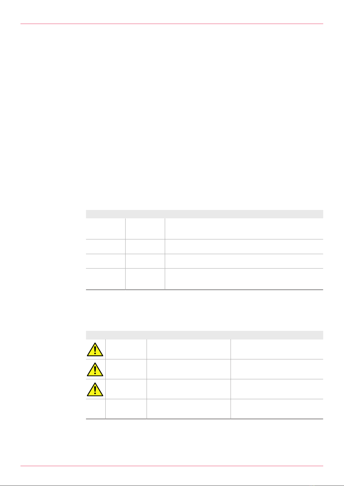
1.4.1 Danger levels ....................................................3
1.4.2 Danger signs.....................................................4
1.4.3 Symbols in this document .................................4
1.4.4 Symbols for personal protective equipment......4
2 Safety .............................................................................. 5
2.1 Proper use .....................................................................5
2.2 Foreseeable misuse ......................................................5
2.3 Obligations of the operator-owner .................................5
2.4 Safety instructions .........................................................6
2.4.1 Fundamental safety instructions .......................6
3 Identification................................................................... 6
3.1 Type code......................................................................6
3.2 Rating plate ...................................................................7
4 Technical data ................................................................ 7
4.1 Operating limits..............................................................7
4.2 Required NPSH values..................................................7
4.3 Sound pressure level.....................................................8
4.4 Output tables .................................................................8
4.5 Mesh width strainer/filter................................................9
4.6 Weights..........................................................................9
5 Function description.................................................... 10
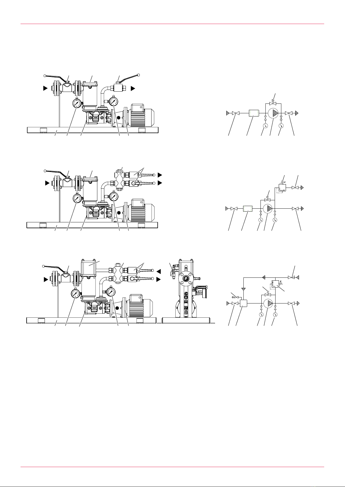
5.1 Structure of standard version ......................................10
5.2 Structure of special design ..........................................11
5.3 Functional principle......................................................11
5.4 Pressure maintaining valve .........................................11
5.5 Pulsation damper.........................................................12
5.6 Expansion valve (optional) ..........................................12
5.7 Protection against soiling.............................................12
5.8 Options for standard version .......................................13
5.9 Options for special design ...........................................13
5.10 Heating system (optional)............................................14
5.10.1 Possible types of heating ................................14
5.10.2 Electrical heating system ................................14
6 Transportation, storage............................................... 14
6.1 Dangers during transportation .....................................14
6.2 Dangers during storage ...............................................14
6.3 Unpacking and checking the state of delivery .............15
6.4 Transporting the pump station.....................................15
6.5 Storing the pump station..............................................15
7 Preservation ................................................................. 16
7.1 Preservation table........................................................16
7.2 Preserving the inner surfaces......................................16
7.3 Preserving the outer surfaces......................................16
7.4 Removing the preservation..........................................17
8 Installation, removal .................................................... 17
8.1 Dangers during installation ..........................................17
8.2 Dangers during removing ............................................17
8.3 Mounting the pump station ..........................................18
8.4 Protecting the pump station against pressure peaks ...18
8.5 Removing the pump station .........................................19
9 Connection.....................................................................20
9.1 Dangers during connection work .................................20
9.2 Connecting the pump station to the pipe system .........20
9.2.1 Setup of the suction line ..................................20
9.2.2 Flange connection ...........................................20
9.2.3 Pipe screwed connection.................................21
9.3 Connecting the pump station to the power supply .......22
10 Operation........................................................................22
10.1 Dangers during operation ............................................22
10.2 Commissioning ............................................................23
10.2.1 Cleaning the pipe system ................................23
10.2.2 Filling and venting the pump station ................23
10.2.3 Checking the direction of rotation ....................24
10.2.4 Commissioning the pump station ....................24
10.2.5 Venting the deaerator ......................................25
10.3 During operation ..........................................................26
10.3.1 Checking the operating pressure.....................26
10.3.2 Adjusting the overflow valve ............................26
10.3.3 Setting the pressure maintaining valve............26
10.3.4 Switching off the pump station.........................27
10.4 Decommissioning.........................................................27
10.4.1 Taking the pump station out of operation ........27
10.5 Recommissioning.........................................................28
10.5.1 Recommissioning the pump station.................28
11 Maintenance...................................................................28
11.1 Dangers during maintenance.......................................28
11.2 Required maintenance.................................................28
11.3 Maintaining the pump station .......................................28
11.4 Maintaining the strainers..............................................29
12 Servicing ........................................................................29
12.1 Dangers during servicing .............................................29
12.2 Signs of wear ...............................................................29
12.3 Servicing the pump station...........................................29
12.4 Replacing the pump .....................................................30
12.5 Cleaning the strainer....................................................31
13 Disposal..........................................................................32
13.1 Dismantling and disposing of the pump station ...........32
14 Troubleshooting ............................................................33
14.1 Possible faults..............................................................33
14.2 Troubleshooting ...........................................................33
15 Spare parts.....................................................................36
15.1 Overview ......................................................................36
16 Appendix ........................................................................38
16.1 Tightening torques for screws with metric screw threads
with and without wedge lock washers..........................38
16.2 Tightening torques for screw plugs with thread
measured in inches and elastomer seal ......................39
16.3 Contents of the Declaration of Conformity ...................39
2OIK 10en-GB Edition 2021-06 Operation instructions

1 About this document
1.1 General information
1 About this document
1.1 General information
These instructions form part of the product and must be kept for future reference. Furthermore please
observe the associated documents.
1.2 Associated documents
oDeclaration of conformity according to EU Directive 2006/42/EC
oManufacturer's declaration according to EU Directive 2014/68/EU
oCorresponding operating instructions of the pump
oTechnical documentation of the supplied components
1.3 Target groups
The instructions are intended for the following persons:
oPersons who work with the product
oOperator-owners who are responsible for the use of the product
Persons who work with the product must be qualified. The qualification ensures that possible dangers
and material damage that are connected to the activity are detected and avoided. These persons are
qualified personnel who carry out the work properly due to their training, knowledge and experience
and on the basis of the relevant provisions.
Information on the required qualification of the personnel is provided separately at the beginning of the
individual chapters in these instructions. The following table provides an overview.
Target group Activity Qualification
Transport
personnel
Transporting,
unloading,
setting up
Qualified personnel for transport, mobile crane operators, crane
operators, forklift operators
Fitter Mounting,
connection
Qualified personnel for mounting
Electrician Electrical
connection
Qualified personnel for electric installation
Trained
personnel
Delegated task Personnel trained by the operator-owner who know the task
delegated to them and the possible dangers arising through
improper behaviour.
Tab.1: Target groups
1.4 Symbols
1.4.1 Danger levels
Signal word Danger level Consequences of non-observance
DANGER Immediate threat of danger Serious personal injury, death
WARNING Possible threat of danger Serious personal injury, invalidity
CAUTION Potentially dangerous situation Slight personal injury
ATTENTION Potentially dangerous situation Material damage
Operation instructions OIK 10en-GB Edition 2021-06 3

1 About this document
1.4 Symbols
1.4.2 Danger signs
Meaning Source and possible consequences of non-observance
Electrical voltage Electrical voltage causes serious physical injury or death.
Raised load Falling objects can result in serious physical injury or death.
kg
Heavy load Heavy loads can result in serious back problems.
Risk of slipping Discharging pumped liquid and oils on the foundation or
tread surfaces can cause falls with serious physical injury
or death.
Flammable substances Discharging pumped liquid and oils can be easily inflam-
mable and can result in serious burns.
Hot surface Hot surfaces can cause burns.
1.4.3 Symbols in this document
Meaning
Warning personal injury
Safety instruction
Request for action
1.
2.
3.
Multi-step instructions for actions
Action result
Cross-reference
1.4.4 Symbols for personal protective equipment
Additional dangers arise for personnel without personal protective equipment. It is imperative that the
personal protective equipment be worn.
Information on the personal protective equipment is provided separately at the beginning of the indi-
vidual chapters in these instructions. The following table provides an overview.
Meaning Possible consequences of non-observance
Protective helmet Serious head injury through falling or toppling parts
Protective goggles Eye injury through hot, poisonous or corrosive liquids
Hearing protection Damage to hearing through loud noises
Heat-resistant protective gloves
with arm protection
Serious burns or cuts
4OIK 10en-GB Edition 2021-06 Operation instructions

2 Safety
2.1 Proper use
Meaning Possible consequences of non-observance
Close fitting work clothing Serious physical injury through clothes being drawn in
Slip resistant safety boots Serious foot injury through falling or toppling parts and seri-
ous physical injury through falling
2 Safety
2.1 Proper use
oUse the pump station solely for transporting lubricating liquids that are chemically neutral and that
do not contain gas or solid components.
oUse the pump station only within the operating limits specified on the rating plate and in the chapter
"Technical data". In the case of operating data that do not agree with the specifications on the rat-
ing plate, please contact the manufacturer.
oThe pump station is designed specially for the operating pressure named by the customer. If the ac-
tual operating pressure deviates notably from this design pressure, damage to the pump station can
also arise within the specified operating limits. This applies both to notably higher as well as to not-
ably lower operating pressures. Under no circumstances may the minimum pressure lie below
2bar. In case of any doubt, please contact the manufacturer.
2.2 Foreseeable misuse
oAny use that extends beyond the proper use or any other use is misuse.
oThe product is not suitable for pumping liquids outside the operational limits.
oAny bypassing or deactivation of safety equipment during operation is prohibited.
2.3 Obligations of the operator-owner
The operator-owner is the person who operates the product commercially or permits a third party to
use it and who bears the legal responsibility for the product, the protection of the personnel and third
parties during its operation.
The product is used in industrial applications. The operator-owner is therefore subject to the statutory
obligations concerning occupational health and safety.
In addition to the safety instructions in these instructions, the regulations on safety, accident prevention
and environmental protection respectively valid for the range of application of the product are to be ob-
served.
Operation instructions OIK 10en-GB Edition 2021-06 5

3 Identification
2.4 Safety instructions
2.4.1 Fundamental safety instructions
The following safety instructions must be observed strictly:
oRead these operating instructions carefully and observe them.
oRead the operating instructions of the components carefully and observe them.
oHave work only carried out by qualified personnel/trained personnel.
oWear personal protective equipment and work carefully.
oPumped liquids can be subject to high pressure and can result in personal injury and damage to
property in case of incorrect operation or damaged components.
oPumped liquids can be hot, poisonous, combustible and caustic. Use corresponding protective
equipment.
oObserve the associated data sheets and safety regulations when handling dangerous materials.
oAvoid skin contact with system parts carrying liquids at operating temperatures exceeding 60°C.
oCollect any discharging pumped liquid safely and dispose of it in an environmentally compatible
manner in accordance with the applicable local regulations. Neutralize residues.
oKeep the mounting surfaces, scaffolding, ladders, lifting platforms and tools clean in order to pre-
vent slipping or stumbling.
oIf pressurized or energized components are damaged, shut down the pump station immediately.
Replace the components.
3 Identification
3.1 Type code
EKL11-1000.AB.0001
1
2
3
4
5
Fig.1: Type code
1Type
2Size
3Shaft seal
4Heating
5Version index
Item Classification Description
1Type EKL Station with pump of the K series for light oils
EKS Station with pump of the K series for heavy fuel oils
EKL/S 11 Without pressure maintaining valve
EKL/S 12 With pressure maintaining valve
EKL/S 13 With pressure maintaining valve and return
2Size Corresponds to delivery rate in [l/min] at 1450 min-1
3Shaft seal A Standard mechanical seal
B Mechanical seal of hard material
C Standard radial shaft seal
D Magnetic coupling
E Mechanical seal with quench
F High-temperature radial shaft seal
X Special design
4Heating A Without heating
B Electrical heating system
5Version index For internal administration
Tab.2: Type code
6OIK 10en-GB Edition 2021-06 Operation instructions

4 Technical data
3.2 Rating plate
3.2 Rating plate
KRAL GmbH, 6890 Lustenau, Austria www.kral.at
pSmax. / pDmax.
Ty p |Type
SN | Serial no.
Tmin. / Tmax. ºC
l/min
mm²/s
kg
min-¹
bar
bar
∆p
Jahr |Year Gewicht | Weight
n
Q
Art.-Nr. | Item no.
1
2
3
5
4
10
7
9
8
6
11
Fig.2: Rating plate
1Construction year
2Max. operating overpressure
suction-side/Max. operating
overpressure pressure-side
3Temperature range
4Serial number
5Type
6Article number
7Differential pressure
8Nominal delivery rate
9Rated speed
10 Nominal viscosity
11 Weight
4 Technical data
4.1 Operating limits
Parameter Unit EKL11 EKL12 EKL13 EKS11 EKS12 EKS13
Max. operating pressure
oPump unit [bar] 6
oStrainer+deaerator [bar] 6
oShut-off devices [bar] 6
oPressure maintaining
valve
[bar] – 6 6 – 6 6
Inlet pressure
omax. [bar] 6
Temperature pumped li-
quid
omin. [°C] -20
omax. [°C] 250
Viscosity
omin. [mm2/s] 2
omax. [mm2/s] 10000
Ambient temperature
omin. [°C] -10
omax. [°C] 50
Tab.3: Operating limits
4.2 Required NPSH values
The required NPSH values of the pump depend on the size, the viscosity of the pumped liquid and the
speed.
The NPSH values are available on the website of the manufacturer:
www.kral.at/en/screw-pumps
Operation instructions OIK 10en-GB Edition 2021-06 7

4 Technical data
4.3 Sound pressure level
Guide values at 1m distance, 1450min-1, 10 bar
Size Sound pressure level ±3 [dB(A)]
Pump Motor Pump unit
240–1000 50.0 42.0 51.0
1800–2300 52.0 44.0 54.0
3200–4000 55.0 50.0 56.0
6000 56.0 50.0 57.0
Tab.4: Sound pressure level
4.4 Output tables
Size of pump station EKL 240 400 500
Size of pump KFN 5 7 10
Unit
Motor output [kW] 0.25 0.25 0.25
Delivery rate at 6mm2/s
o50Hz, 1450 min-1
o3 bar [l/h] 210 336 462
o6 bar [l/h] 168 276 390
o60Hz, 1750min-1
o3 bar [l/h] 276 432 588
o6 bar [l/h] 234 372 522
Filter area [cm2] 320
Tab.5: Output table EKL240–500
Size of pump station EKL 750 1000 1800
Size of pump KFN 7 10 15
Unit
Motor output [kW] 0.37 0.55 0.55
Delivery rate at 6mm2/s
o50Hz, 2900 min-1
o10 bar [l/h] 804 1086 1662
o30 bar [l/h] 750 1020 1578
o60Hz, 3400min-1
o10 bar [l/h] 966 1302 1980
o30 bar [l/h] 912 1236 1902
Filter area [cm2] 320
Tab.6: Output table EKL750–6000
8OIK 10en-GB Edition 2021-06 Operation instructions

4 Technical data
4.5 Mesh width strainer/filter
Size of pump station EKS 240 400 500
Size of pump KFN 5 7 10
Unit
Motor output [kW] 0.25 0.25 0.25
Delivery rate at 6mm2/s
o50Hz, 1450 min-1
o3 bar [l/h] 276 426 570
o6 bar [l/h] 264 408 546
o60Hz, 1750min-1
o3 bar [l/h] 342 522 702
o6 bar [l/h] 330 504 678
Filter area [cm2] 320
Tab.7: Output table EKS240–500
Size of pump station EKS 750 1000 1800 2300 3200 4000 6000
Size of pump KFN 7 10 15 20 32 42 55
Unit
Motor output [kW] 0.37 0.55 0.55 0.75 1.5 2.2 3.0
Delivery rate at 6mm2/s
o50Hz, 2900 min-1
o3 bar [l/h] 894 1200 1794 2358 3750 4992 6840
o6 bar [l/h] 876 1176 1764 2322 3708 4938 6768
o60Hz, 3400min-1
o3 bar [l/h] 1056 1416 2112 2778 4410 5880 8052
o6 bar [l/h] 1038 1392 2088 2742 4368 5820 7974
Filter area [cm2] 320 720
Tab.8: Output table EKS750–6000
4.5 Mesh width strainer/filter
Options Usage Viscosity
[mm2/s]
Mesh width
[mm]
Strainer Separation of coarse soiling during
operation
< 20 0.25
> 20 0.5
Commissioning strainer/
commissioning filter
Protection of the station during
commissioning
– 0.02
Operating filter Protection of the station during
operation
– Depending on
pumped liquid
Tab.9: Mesh width strainer/filter
4.6 Weights
The weight is specified on the rating plate.
Operation instructions OIK 10en-GB Edition 2021-06 9

5 Function description
5.1 Structure of standard version
5 Function description
5.1 Structure of standard version
46
8
2
010
bar
46
8
2
010
bar
10 17 26 18 1
6 2 6
6 6
217 18
1
26
Fig.3: EKL/EKS 11
46
8
2
010
bar
46
8
2
010
bar
10 17 26 18 1
6 2 6
66
217 181
26
7 6
7
Fig.4: EKL/EKS 12
46
8
2
010
bar
46
8
2
010
bar
10 17 26 18 1
636
66
317 181
26
7
6
7
12
12
Fig.5: EKL/EKS 13
1Pump unit 10 Base frame
2Strainer 12 Deaerator venting
3Deaerator with integrated strainer 17 Suction-side pressure gauge
6Ball valve 18 Pressure-side pressure gauge
7Pressure maintaining valve 26 Overflow valve pump
10 OIK 10en-GB Edition 2021-06 Operation instructions

5 Function description
5.2 Structure of special design
1017 26 18 1
2
217 18
1
26
Fig.6: EKS11 special design
1Pump unit 17 Suction-side pressure gauge
2Strainer 18 Pressure-side pressure gauge
10 Base frame 26 Overflow valve pump
5.3 Functional principle
The pump station of the EKL/EKS series is a fuel oil transfer pump station and in the basic module con-
sists of a screw pump of the series KFN1, large-area strainer2, suction-side and pressure-side ball
valves6 as well as shut-off pressure gauges17,18 on the suction side and pressure side. The basic
module can be extended with a pressure maintaining valve7 and a deaerator with integrated
strainer3. The drawn oil flows through the suction-side shut-off devices and the strainer to the suction
side of the pump which pumps the liquid into the pressure line. The suction-side pressure gauge shows
the pressure between strainer and pump as well as the soiling of the strainer. The pressure-side pres-
sure gauge is used to monitor operation. You can find detailed information in the associated pump op-
erating instructions.
5.4 Pressure maintaining valve
T P
T P
B
A
C
The pressure maintaining valve is used to regulate the pressure by means of an overflowing partial
volume flow. The pressure maintaining valve is a directly controlled spring-loaded piston valve that
keeps or limits the pressure prevailing in the pressure lineP to an operating pressure or maximum
pressure set by means of the pressure spring. The excess liquid is drained into the connection of
thereturn lineT. A flow rate in the pressure line that is too low, arising for example when a ball valve is
closed, can result in overheating and damage to the pump. Pump operation with an overflow of the
complete delivery rate for more than 45 seconds is therefore not permitted without prior consultation
with the manufacturer.
The set pressure of the valve can be adjusted by means of an Allen key, Ä During opera-
tion,Page26.
Operation instructions OIK 10en-GB Edition 2021-06 11

5 Function description
5.5 Pulsation damper
As a mechanical regulating valve, the pressure maintaining valve has a certain sluggishness. There-
fore rapid changes in the flow rate (for example usage of rapid switching valves, starting of the pump
without soft start) and rigid pipe systems can result in brief pressure peaks. To avoid operating prob-
lems or damage to system components, a pulsation damper can be installed in the pipe system, Ä In-
stallation, removal,Page17. As an alternative such a pulsation damper can also be mounted directly
at the pump station. The pulsation damper is available from the manufacturer.
5.6 Expansion valve (optional)
1 2 3 4
6 5
Fig.7: Structure of expansion valve
1Screw plug 4Valve body
2Adjusting screw 5Inflow from the station
3Pressure spring 6Overflow
When the station is switched off, thermal expansion of the fluid volume which is caused by heating up
can result in an impermissibly high inner pressure. To prevent this a spring-loaded expansion valve is
offered as an option, which relieves any overpressure arising in the station. This expansion valve is set
in the factory to an opening pressure of 5bar.
5.7 Protection against soiling
4
3
2
1
1
2
3
4
5
Fig.8: Strainer (left) / Deaerator with integrated strainer (right)
1Strainer cover 4Drain screw
2Conical spring 5Venting
3Strainer insert
12 OIK 10en-GB Edition 2021-06 Operation instructions

5 Function description
5.8 Options for standard version
The pump station is equipped with one or two strainers as standard. However, these are not capable of
separating larger amounts of soiling occurring regularly or abrasive fine particles. If such operating con-
ditions occur, the station has to be protected additionally by a correspondingly dimensioned operating
filter. Very fine abrasive particles can, however, not be held back by the operating filter and cause in-
creased wear to the pumps. Alternatively the strainers can be replaced during commissioning by fine-
meshed commissioning strainers. A further possibility is the use of an external commissioning filter.
The strainer inserts are made of metal and can be cleaned and reused, Ä Servicing,Page29.
5.8 Options for standard version
5
4
1
2
3
6
Fig.9: EKL/EKS 11
5
4
1
2
3
6
7
Fig.10: EKL/EKS 12
5
4
1
2
3
6
9
8
Fig.11: EKL/EKS 13
1Electrical heating system strainer 6Non-return valve pressure-side
2Differential pressure indicator 7Override switch for ball valve
3Leak oil monitoring 8Venting with time control
4Ball valve with limit switch 9Expansion valve
5Pressure monitor in the pressure line
5.9 Options for special design
oLeak oil monitoring
Operation instructions OIK 10en-GB Edition 2021-06 13

6 Transportation, storage
5.10 Heating system (optional)
5.10.1 Possible types of heating
The pump station can optionally be equipped with a heating system. The manufacturer recommends a
heating system at high-viscosity pumped liquids that do not flow sufficiently if not heated. This can res-
ult in excessive wattage or in problems arising through cavitation or sealing.
Possible types of heating:
oElectrical heating system pump
oElectrical heating system strainer
5.10.2 Electrical heating system
The output of the heating elements corresponds to the radiation and convection losses of the station in
the required temperature range so that overheating is not possible.
Electrical heating system pump
Detailed information is provided in the associated operating instructions of the pump.
Electrical heating system strainer
The heating element is inserted into the strainer chamber and fastened with a special cover. The oil
heated up in the strainer also enters the pump and thus ensures reliable starting.
Parameter Unit Value
Voltage [V] 230
Heating output [W] 180
Wire cross-section [mm2] 2 x 1
Tab.10: Operating data
6 Transportation, storage
6.1 Dangers during transportation
The following safety instructions must be observed
oHave all work only carried out by authorized qualified personnel.
oA crane operator and transport personnel are required for transportation (2 persons).
oUse intact and correctly dimensioned hoisting equipment.
oEnsure that the means of transport is in a flawless state.
oEnsure that the centre of gravity of the load is taken into consideration.
oDo not stand under raised loads.
oCordon off the danger zone and ensure that unauthorized persons cannot enter the danger zone.
6.2 Dangers during storage
The following safety instructions must be observed:
oObserve the storage conditions.
14 OIK 10en-GB Edition 2021-06 Operation instructions

6 Transportation, storage
6.3 Unpacking and checking the state of delivery
1. Upon delivery unpack the pump station and check it for damage during transportation.
2. Report damage during transportation immediately to the manufacturer.
3. Dispose of packaging material in accordance with the locally applicable regulations.
6.4 Transporting the pump station
Personnel qualification: oTransport personnel
Personal protective equipment: oWork clothing
oProtective helmet
oProtective gloves
oSafety boots
Aids: oMobile crane, forklift, hoisting equipment
oTraverse
WARNING
Risk of injury and damage to equipment through falling and toppling parts.
► Use intact and correctly dimensioned hoisting equipment in accordance with the total weight to be
transported.
► Select the lift points for the hoisting equipment in accordance with the centre of gravity and the
weight distribution.
► Use at least two load ropes.
► Do not stand under raised loads.
Fig.12: Fastening of hoisting equipment - principle diagram
Secure the hoisting equipment to the pump station and lift the pump station using the crane.
6.5 Storing the pump station
During the test run, the internal components of the pump station are wetted with test oil, which has a
preservative effect. The pipe connections are fitted with protective covers. Unless otherwise specified,
the outer parts of the pump station are preserved with a single-coat PU-based two-component paint.
The preservative applied at the factory will protect the pump station for about six weeks, if it is stored in
a dry and clean location.
The manufacturer offers a long-term preservation for storage times of up to 60months. The pump sta-
tion is additionally packed in hermetically sealing anti-corrosion paper.
Personnel qualification: oTransport personnel
Aids: oMobile crane, forklift, hoisting equipment
Operation instructions OIK 10en-GB Edition 2021-06 15

7 Preservation
7.1 Preservation table
ATTENTION
Damage to equipment and corrosion if stored improperly and during longer standstills.
► Protect the pump station against damage, heat, sunlight, dust, moisture and magnetic fields.
► Protect against corrosion during longer standstill.
► Observe measures for storing and preservation.
1. Store cool and dry and protect against sunlight.
2. Ensure that the anti-corrosion paper is not damaged.
3. Observe the intervals for preservation Ä Preservation,Page16.
7 Preservation
7.1 Preservation table
Preservation has to be carried out additionally under the following conditions:
Type of delivery Condition
Standard delivery oStorage time exceeding six weeks
oUnfavourable storage conditions such as high humidity, salty
air, etc.
Delivery with long-term preservation oOpened or damaged packaging
Tab.11: Conditions for additional preservation
7.2 Preserving the inner surfaces
Personnel qualification: oTrained personnel
Personal protective equipment: oWork clothing
oProtective gloves
oSafety boots
Aids: oPreservative (acid-free and resin-free oil)
1. Close the pipe connections of the station.
2. Open the strainer cover. Fill the preservative into the strainer chamber, while slowly turning the
pump at the fan impeller of the motor in the direction of rotation. Do not fill the strainer com-
pletely, but leave approx. 2 cm height empty. Close the strainer cover.
3. After about six months storage check the filling level of the preservative and if necessary top up.
7.3 Preserving the outer surfaces
Personnel qualification: oTrained personnel
Personal protective equipment: oWork clothing
oFace protection
oProtective gloves
oSafety boots
Aids: oCalcium complex grease (for example
TEVIER®GREASEWAWE100 with adhesive additive)
oCastrol Rustilo DWX 33 or other preservative offering compar-
able protection
1. Brush calcium complex grease corrosion protection (for example TEVIER® FETT WAWE 100
with adhesive additive) to the mounting surfaces.
2. Brush or spray preservative (for example Castrol Rustilo DWX 33) onto the process connections
and remaining plain and unpainted parts.
3. At intervals of about six months check the preservation and if necessary repeat.
16 OIK 10en-GB Edition 2021-06 Operation instructions

8 Installation, removal
7.4 Removing the preservation
Personnel qualification: oTrained personnel
Personal protective equipment: oWork clothing
oProtective gloves
oSafety boots
Aids: oSolvent
oSteam-jet cleaning device with wax-dissolving additives
oCollection tank
CAUTION
Risk of injury through discharging preservative.
► Wear personal protective equipment during all the work.
► Collect any discharging preservative safely and dispose of it in an environmentally compatible
manner in accordance with the applicable local regulations.
1. Clean the outside of the pump station with solvents, if necessary using a steam-jet cleaning
device.
2. Remove the strainer cover carefully in order to reduce any pressure that may exist in the pump
station.
3. Drain the pump station, collecting the preservative in a collection tank.
4. To remove the residual preservative, flush the pump station with the pumped liquid.
8 Installation, removal
8.1 Dangers during installation
The following safety instructions must be observed strictly:
oHave all work carried out only by authorized qualified personnel.
oBefore installation ensure that the operating limits, NPSH values and ambient conditions are ob-
served.
oObserve the tightening torques Ä Appendix,Page38.
oEnsure that all the components can be accessed and that maintenance work can be carried out
easily.
8.2 Dangers during removing
The following safety instructions must be observed strictly:
oHave all work carried out only by authorized qualified personnel.
oBefore beginning work, let the pump unit cool down to the ambient temperature.
oCollect any discharging pumped liquid safely and dispose of it in an environmentally compatible
manner in accordance with the applicable local regulations.
oEnsure that the collection tank for discharging pumped liquid is sufficiently large.
Operation instructions OIK 10en-GB Edition 2021-06 17

8 Installation, removal
8.3 Mounting the pump station
Notice Soiling in the pipe system impairs the service life of the pump station. If the pipe system is flushed us-
ing the pump station during the initial commissioning, an additional commissioning filter has to be in-
stalled temporarily before the pump station. Alternatively the strainers supplied as standard can be re-
placed during commissioning by fine-meshed commissioning strainers.
Personnel qualification: oTransport personnel
oFitter
Personal protective equipment: oWork clothing
oProtective gloves
oSafety boots
Aids: oMobile crane, forklift, hoisting equipment
WARNING
Risk of injury and damage to equipment through falling and toppling parts.
► Only fasten the pump station on a stable bearing underground.
► Ensure that fastening elements and pipings are fastened sufficiently.
ATTENTION
Damage to device through impurity in the pipe system.
► During welding work attach protective covers in front of the connecting flanges.
► Ensure when welding that welding beads and abrasive dust cannot get into the pipe system and
the pump station.
► Ensure that a commissioning filter is installed when the pipe system is flushed and cleaned using
the pump.
Requirement:
üPump station connections protected against soiling, for example by using the protective cover
mounted in the factory
1. Bring the pump station into the installation position.
2. Fasten the pump station with fastening elements securely on the underground.
3. After the connecting work clean the pipe system thoroughly Ä Commissioning,Page23.
8.4 Protecting the pump station against pressure peaks
ATTENTION
Damage to the plant components through pressure peaks.
► Use pulsation damper.
Notice The pulsation damper is available as an option from the manufacturer.
Install the pulsation damper in the pipe system.
-or-
Mount the pulsation damper on the pump station.
18 OIK 10en-GB Edition 2021-06 Operation instructions

8 Installation, removal
8.5 Removing the pump station
Personnel qualification: oTransport personnel
oFitter
oElectrician
Personal protective equipment: oWork clothing
oProtective helmet
oFace protection
oProtective gloves
oSafety boots
Aids: oMobile crane, forklift, hoisting equipment
oSolvents or industrial cleaners suitable for the pumped liquid
oCollection tank
DANGER
Risk of death resulting from electric shock.
► Ensure that the electrical power supply is de-energized and is secured against being switched
back on.
► Observe the operating instructions of the electrical components.
DANGER
Risk of death resulting from falling load.
► Use intact and correctly dimensioned hoisting equipment.
► Ensure that the crane and hoisting equipment are in a flawless state.
► Do not stand under raised loads.
► Take the centre of gravity into account and secure the load against tilting.
► A crane operator and transport personnel are required for transportation (2 persons).
DANGER
Risk of death through emitted pumped liquid.
Pumped liquids can be hot, poisonous, combustible and caustic and can spray out under high pres-
sure.
► Wear personal protective clothing during all the work. Ensure face protection.
► Before beginning work, let the pump station cool down to the ambient temperature.
► Ensure that the pump station is depressurized.
► Collect any discharging pumped liquid safely and dispose of it in an environmentally compatible
manner in accordance with the applicable local regulations.
Requirement:
üPump station and pumped liquid cooled down to the ambient temperature
1. Ensure that the pump station is deenergized and is secured against being switched back on.
2. Ensure that the pump station is depressurized.
3. Disconnect the pump station from the pipe system and drain it. Collect any liquids that are
emitted.
4. Dismantle the pump station on site or transport it to a suitable site. Take the information on trans-
portation into account.
Operation instructions OIK 10en-GB Edition 2021-06 19

9 Connection
9.1 Dangers during connection work
9 Connection
9.1 Dangers during connection work
The following safety instructions must be observed strictly:
oHave all work on the pump station and pipe system only carried out by authorized qualified per-
sonnel.
oEnsure that impurities cannot get into the pump station and pipe system.
oEnsure that mechanical connections are mounted stress-free.
oObserve the tightening torques.
oHave all the work on the electrical equipment only carried out by electricians.
oBefore commissioning ensure correct earthing, equipotential bonding and overcurrent protection.
oBefore beginning work on the pump station ensure that the electrical power supply is deenergized
and is secured against being switched back on.
oIf the insulation of the electrical cables or wires is damaged, disconnect the power supply
immediately.
9.2 Connecting the pump station to the pipe system
9.2.1 Setup of the suction line
Fig.13: Setup of the suction line
Lay the suction line hermetically sealed. If preheated heating oils are pumped, install the tank above
the station and lay the suction line without siphon or pipe elbow.
9.2.2 Flange connection
Fig.14: Pipe connection
Personnel qualification: oFitter
Personal protective equipment: oWork clothing
oProtective gloves
oProtective helmet
oSafety boots
Aids: oMobile crane, forklift, hoisting equipment
oTorque wrench
20 OIK 10en-GB Edition 2021-06 Operation instructions
This manual suits for next models
5
Table of contents
Other KRAL Water Pump manuals