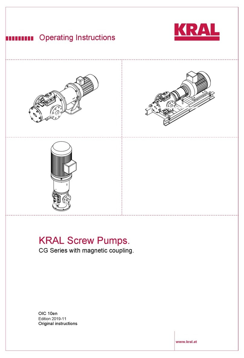
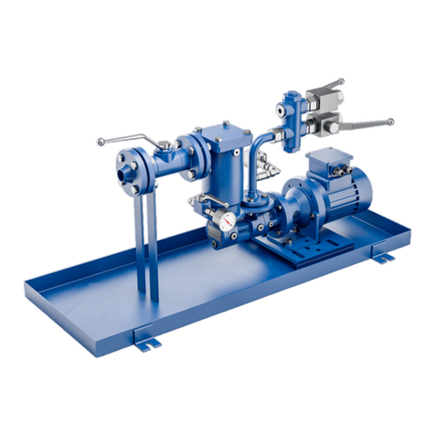
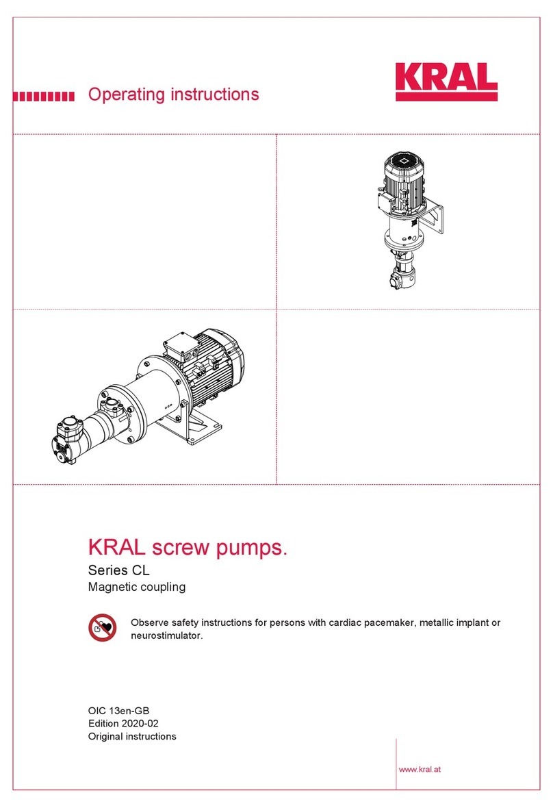
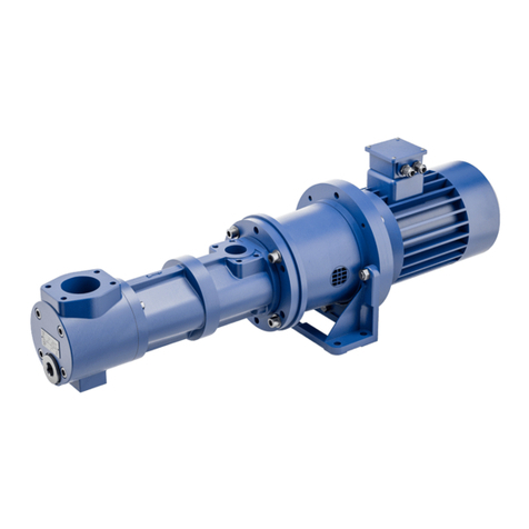
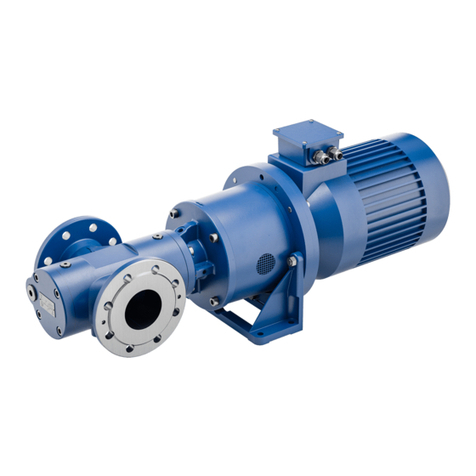
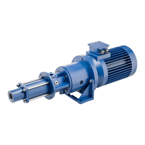
KRAL CLC Series User manual

Product Specification Sheet
X-Cel House, Chrysalis Way, Langley Bridge, Eastwood, Nottinghamshire NG16 3RY
Operating Instructions
KRAL Screw Pumps.
CLC Series – High viscosity
OIC 12en
Edition 08/2016
Original instructions

2 OIC 12en Edition 08/2016 Operating Instructions
Table of contents
KRAL Screw Pumps – CLC Series – High viscosity
About this document
□General information 3
□Target groups 3
□Symbols 3
□Danger levels 3
□Associated documents 4
Safety
□Proper use 5
□Safety information 5
Identification
□Type code 6
□Rating plate 6
Technical data
□Operating limits 7
□Sound pressure level 7
□Required NPSH values 7
□Weights 7
Heating
□General 8
□Fluid heating system 8
▪Mounting the fluid heating system 8
▪Commissioning the fluid heating system 8
Function description
□Structure 9
□Radial shaft seal 11
□Direction of rotation and flow direction 11
Transportation, storage and disposal
□Unpacking and checking the state of
delivery 12
□Lifting the pump 12
□Storage 12
□Preservation 13
▪Preserving the internal surfaces of the
pump 13
▪Preserving the external surfaces of the
pump 13
▪Removing the preservation 13
□Disposing of the pump 14
Installation, removal and connection
□Installation 15
▪Installing the pump 15
▪Protecting the pump against soiling 15
▪Connecting the pump to the pipe system 16
▪Assembling the pump and motor 16
□Connecting the motor 17
□Removing the pump 18
Operation
□Commissioning 19
▪Cleaning the pipe system 19
▪Filling sealing chambers 19
▪Variant 1: Checking PTFE grease 20
▪Variant 2: Filling sealing chamber B
with quench liquid via quench tank 20
▪Variant 3: Filling the sealing chamber B
with quench liquid via the circulation line 21
▪Filling and venting the pump 22
▪Checking the direction of rotation 22
▪Commissioning the pump 23
□During operation 24
▪Checking the operating pressure 24
□Switching off the pump 24
□Decommissioning the pump 24
□Recommissioning the pump 25
Servicing
□Safety instructions 26
□Required maintenance 26
▪Maintenance schedule 26
□Cleaning the pump 27
□Lubricating the ball bearings 29
□Lubricating the radial shaft seal 30
□Refilling quench liquid 31
Troubleshooting
□Possible faults 32
□Troubleshooting 32
Appendix
□General drawings 35
□Spare parts 37
□Tightening torques 38
□Contents of the EC Declaration of
Conformity 38
□Notes 39

Operating Instructions OIC 12en Edition 08/2016 3
General information
About this document
About this doc ument General information
The operating instructions form part of the pump or pump unit. In the following a distinction between
pump and pump unit is only made when it is relevant for the understanding.
The operating instructions must be kept for future reference.
Furthermore please observe the associated documents.
Target groups
Symbols
Danger levels
Target group Tasks
Operator-owner □Keep these instructions available at the system site for future refe-
rence.
□Ensure that employees read and observe these instructions and the
associated documents, in particular the safety instructions and war-
nings.
□Observe additional system-specific directives and regulations.
Specialist personnel, fitters □Read, observe and follow these instructions and the associated
documents, in particular the safety instructions and warnings.
Symbol Meaning
Warning personal injury
Note
Procedures mechanical installation
Procedures electrical installation
Check or fault table
Request for action
Warning Danger level Consequences of non-observance
DANGER Immediate threat of danger Serious physical injury, death
WARNING Possible threat of danger Serious physical injury, invalidity
CAUTION Potentially dangerous situation Slight personal injury
CAUTION Potentially dangerous situation Material damage

4 OIC 12en Edition 08/2016 Operating Instructions
Associated documents
About this document
Associated documents
ATEX supplementary instructions for operation in potentially explosive areas
Declaration of conformity according to EU Directive 2006/42/EC
Declaration of conformity according to EU Directive 2014/34/EU
Manufacturer's declaration according to EU Directive 2014/68/EU
Technical documentation for supplied components

Operating Instructions OIC 12en Edition 08/2016 5
Proper use
Safety
Safety Proper use
□Use the pump solely for transporting lubricating liquids that are chemically neutral and that contain
no gas or solid components.
□Use the pump only within the operating limits specified on the rating plate and in the chapter "Techni-
cal data". In the case of operating data that do not agree with the specifications on the rating plate,
please contact the manufacturer.
□The pump is designed specially for the operating pressure named by the customer. If the actual ope-
rating pressure deviates notably from this design pressure, damage can also arise within the speci-
fied operating limits. This applies both to notably higher as well as to notably lower operating pressu-
res. Under no circumstances should the operating pressure drop below the minimum pressure of 2
bar. In case of any doubt, please contact the manufacturer.
Safety information
The following general safety instructions must be observed:
□No liability is accepted for damage arising through non-observance of the operating instruc-
tions.
▪Read the operating instructions carefully and observe them.
▪The operator-owner is responsible for the observance of the operating instructions.
▪Installation, removal and installation work may only be carried out by specialist personnel.
□Observe the general regulations for the prevention of accidents as well as the local safety
and operating instructions.
□Observe the valid national and international standards and specifications of the installation
location.
□In case of systems with an increased potential of danger to humans and/or machines the fai-
lure of a pump may not lead to injuries or damage to property.
▪Always equip systems with an increased potential of danger with alarm equipment.
▪Maintain and check the protective/alarm equipment regularly.
□The pumped liquids can be dangerous (for example hot, caustic, poisonous, combustible).
Observe the safety regulations for handling dangerous materials.
□Pumped liquids can be subject to high pressure and can cause damage and/or personal
injury should leaks occur.

6 OIC 12en Edition 08/2016 Operating Instructions
Type code
Identification
Identification Type code
Tab. 1 Type code
Rating plate
1Model
2Size
3Shaft seal
4Pressure stage
5Bearing/heating system/
Pump housing material
6Suction-side accessories
7Completion
8Version index
Fig. 1 Type code
Item Designation Type
1Model CLC: □Pump with free shaft end
□Pump unit in flanged version,
with or without pump bracket foot
2Size Corresponds to delivery rate in [l/min] at 1450 min-1
3Shaft seal F: PTFE seal with quench
4Pressure stage overflow valve Z: without valve
5Bearing/Heating system/
Pump housing material
X: Special design
6Suction-side accessories X: Special design
7Completion K: Unit with coupling and pump bracket, without motor
8Version index For internal administration
1Year of construction
2Differential pressure/
operating pressure max.
3Temperature range
4Serial number
5Type
6Nominal delivery rate
7Rotation speed
8Nominal viscosity
Fig. 2 Rating plate
CLC-550.FZXXK.00021
12
3
4
5
8
7
6
Serial no.
1
2
3
4
5
6
7
8

Operating Instructions OIC 12en Edition 08/2016 7
Operating limits
Technical data
Technical data Operating limits
Tab. 1 Operating limits
Sound pressure level
Guide values at 1 m distance, 1450 min-1, 20 bar
Tab. 2 Sound pressure level
Required NPSH values
Please contact the manufacturer to determine the necessary NPSH values.
Weights
Tab. 3 Weights
Unit CLC 55 CLC 550
Max. operating pressure [bar] 63 63
Max. inlet pressure [bar] 10 10
Max. temperature of pumped liquid [°C] 60 60
Ambient temperature [°C] -10 ... 50 -10 ... 50
Viscosity min. – max. [mm2/s] 3 – 2000000 3 – 2000000
Speed min. – max. [min-1]50 – 2900 50 – 2900
Unit CLC 55 CLC 550
Sound pressure level max. ± 3 [db(A)] 57 70
Unit CLC 55 CLC 550
Pump with free shaft end [kg] 30 130
Completion [kg] 17 75

8 OIC 12en Edition 08/2016 Operating Instructions
General
Heating
Heating General
The pump CLC 55 can optionally be equipped with a heating system (CLC 550 on request). The manu-
facturer recommends heating systems for high-viscosity liquids that do not flow sufficiently if not heated.
High viscosity can result in excessive power consumption or to problems arising through cavitation or
sealing.
Method of heating:
□Fluid heating system
Fluid heating system
The fluid heating system consists of a heating system 241 attached additionally to the pump housing
through which a heating liquid (for example vapour, thermal oil) flows.
Operating data:
□Maximum pressure: 16 bar
□Maximum liquid temperature: 220 °C
Mounting the fluid heating system
Scope of delivery:
1. Mount the heating cover to the pump housing using the supplied socket screws.
2. Mount the piping.
Commissioning the fluid heating system
Required heating-up period for the temperature difference of 20 °C or 50 °C at a liquid temperature of
200 °C see Fig. 1, page 8:
Tab. 1 Heating-up periods for fluid heating system (values apply for pumps without thermal insulation)
► Observe the permissible operating limits of the pump when setting the supplied mass flow and its
temperature, see Tab. 1, page 7.
Fig. 1 Fluid heating system CLC 55
CL 55
□1 heating cover
□2 socket screws
H
G1/4“
L
241
241
Size H L G Steam amount
Heating-up period [min] at a temperature difference of
[kg/h] 20 °C 50 °C
CL 55 67 110 1/4" 320 40
WARNING
Danger of the pump housing bursting and danger of injury through emitted pumped liquid through the
heat expansion of the pumped liquid.
► Open all the valves during the heating process.

Operating Instructions OIC 12en Edition 08/2016 9
Structure
Function description
Function description Structure
Fig. 1 Structure CLC 55
Fig. 2 Structure CLC 55 with completion
Fig. 3 Structure CLC 550
1
2
3
4
5
6
7
8
9
10
11
12
13 14 15 16 15
17
12
3
4
5
6
7
8
9
10
11
12

10 OIC 12en Edition 08/2016 Operating Instructions
Structure
Function description
KRAL screw pumps of the CLC series – high viscosity are generally suitable for transporting lubricating
liquids with high viscosity.
The design with outside bearings does not come into contact with liquid and is therefore especially suita-
ble for pumped liquids that harden when they cool down, tend to crystallize or are abrasive.
Fig. 4 Structure CLC 550 with completion
1Suction cover
2Pump housing
3Flange cover
4Bearing housing
5Radial shaft seal
6Ball bearing
7Running sleeve
8Seal housing
9Balancing cylinder
10 Union flange
11 Insert sleeve
12 Main screw
13 Pressure flange
14 Pump bracket
15 Coupling half
16 Coupling intermediate ring
17 Pump bracket foot
13
14 15 16 15

Operating Instructions OIC 12en Edition 08/2016 11
Radial shaft seal
Function description
Radial shaft seal
The shaft is sealed with a radial shaft seal with three radial shaft sealing rings. Lubrication of the radial
shaft seals is effected via the sealing chambers. The sealing chamber A is filled and vented via the
inlet 1, the sealing chamber B via the inlet 2 and the sealing chamber C via inlet 3.
Depending on the application the six inlets to the three sealing chambers are designed and filled diffe-
rently.
□Sealing chamber A: Application-specific, for example PTFE grease for lubrication of the balancing
cylinder
□Sealing chamber B: PTFE grease or quench liquid (supply via quench tank or circulation line)
□Sealing chamber C: PTFE grease (in the factory)
Direction of rotation and flow direction
Standard direction of rotation:Clockwise, viewed from the drive
Marked on the bearing housing by two arrows
Flow direction: Marked on the pump housing by two arrows
Fig. 5 Sealing chambers A, C Fig. 6 Sealing chamber B (View rotated)
Fig. 7 Direction of rotation and flow direction
AC
13
13
B
2
2

12 OIC 12en Edition 08/2016 Operating Instructions
Unpacking and checking the state of delivery
Transportation, storage and disposal
Transportation , storage an d disposal Unpacking and checking the state of delivery
1. Upon delivery unpack the pump and check for transport damage.
2. Report damage during transportation immediately to the manufacturer.
3. Dispose of packaging material in accordance with the locally applicable regulations.
Lifting the pump
Notice: If the motor and the pump are set up at an angle of 90° to each other, the centre of gravity lies
over the pump, see "Structure", page 9. The pump therefore has to be specifically secured against tilting
at the hoisting equipment after it has been placed and before loosening the hoisting equipment.
1. Attach the hoisting equipment to the pump, and lift the pump.
2. After it has been placed, ensure that the pump is secured against tilting.
Storage
During the test run, the internal components of the pump are wetted with test oil, which has a preserva-
tive effect. The pipe connections are fitted with protective covers. Unless otherwise specified, the exter-
nal components of the pump are preserved with a single-coat PU-based two-component paint. The pre-
servative applied at the factory will protect the pump for about six weeks, if it is stored in a dry and clean
location. The manufacturer offers a long-term preservation for storage times of up to 60 months. To this
purpose the pump is additionally packed in hermetically sealing anti-corrosion paper.
Fig. 1 Fastening hoisting equipment – Principle diagrams
DANGER
Risk of injury and/or damage to equipment by tilting and falling of the pump.
► Use intact and correctly dimensioned hoisting equipment in accordance with the total weight to be
transported.
► Fasten hoisting equipment in accordance with the figures and corresponding to the centre of gra-
vity and weight distribution.
► Use at least two load ropes.
► Secure motor additionally against tilting. Separate motor and pump, if necessary.
► Do not stand under raised loads.

Operating Instructions OIC 12en Edition 08/2016 13
Preservation
Transportation, storage and disposal
Preservation
Preservation has to be carried out in the following cases:
□For standard delivery: For storage periods exceeding six weeks and in case of adverse storage
conditions such as high humidity, salty air, etc.
□For delivery with long-term preservation: If the packaging has been opened or damaged
Preserving the internal surfaces of the pump
1. Close the suction connection of the pump with a blind flange.
2. Pour non-corrosive, resin-free oil into the pressure connection until it reaches approx. 2 cm under
the pressure flange, while slowly turning the main screw against the direction of rotation.
3. Close the pressure connection of the pump with a blind flange.
After about six months storage check the oil level and if necessary top up oil.
Preserving the external surfaces of the pump
Aids:
□Preservative (e.g. Castrol Rustilo DWX 33)
► Paint or spray the preservative onto all plain and unpainted parts.
At intervals of about six months check the preservation and if necessary repeat.
Notice: Store the preserved pump cool and dry and protect it against direct sunlight.
Removing the preservation
Aids:
□Solvent
□Steam-jet cleaning device with wax-dissolving additives
□Collection tank
1. Clean the outside of the pump with solvents, if necessary using a steam-jet cleaning device.
2. Remove the blind flange on the pressure side.
3. Drain the pump, collecting the preservative oil in a collection tank.
4. Remove the blind flange on the suction side.
5. To remove the residual oil, rinse the pump with the pumped liquid.
CAUTION
Risk of injury through emitted preservative oil.
► Wear protective equipment during all the work.
► Open the blind flange carefully in order to reduce any pressure that may exist in the pump.
► Collect the emitted preservative oil safely and dispose of it in an environmentally compatible man-
ner.

14 OIC 12en Edition 08/2016 Operating Instructions
Disposing of the pump
Transportation, storage and disposal
Disposing of the pump
Aids:
□Solvents or industrial cleaners suitable for the pumped liquid
□Collection tank
1. Disassemble the pump and collect the residues of the pumped liquid in a collection tank.
2. Clean residues of the pumped liquid from the individual parts.
3. Separate the sealing elements made of elastomer from the pump and dispose of them in the residual
waste.
4. Recycle iron parts.
WARNING
Danger of poisoning and environmental damage from the pumped liquid.
► Wear protective equipment during all the work.
► Before disposing collect the discharging pumped liquid and dispose of in accordance with the
locally applicable regulations.
► Before disposing neutralize the residues of the pumped liquid.

Operating Instructions OIC 12en Edition 08/2016 15
Installation
Installation, removal and connection
Installat ion, removal and connect ion Installation
Installing the pump
The pumps can be operated in any mounting position. However, the manufacturer recommends that the
pump not be mounted above the motor since pumped liquid can ingress the motor if a leak occurs.
Requirement:
□The pump connections are to be protected against soiling, for example by using the protective cover
mounted in the factory
1. Place the pump in position, while ensuring that the flow direction that is marked by arrows on the
pump housing is correct.
2. Fasten the pump with fastening elements securely on the underground.
Protecting the pump against soiling
► After the connecting work clean the pipe system thoroughly, see "Cleaning the pipe system",
page 19.
Observe the following instructions:
□When selecting the location take the operating limits, NPSH values and ambient conditions
into account, see "Technical data", page 7.
□The function, safety and service life may not be impaired by humidity, temperature influences
or explosive atmospheres.
□During the installation ensure that the pump is secured against tilting.
□During the installation ensure that all the parts can be accessed easily and that the main-
tenance work can be carried out easily.
WARNING
Risk of injury and damage to equipment should the pump fall over.
► Observe the centre of gravity of the pump and if necessary secure the pump against falling over.
CAUTION
Leaking pumped liquid can damage the motor.
► Do not mount the pump above the motor.
CAUTION
Damage to the pump and piping through insufficient fastening.
► Only fasten the pump on a stable bearing underground.
► Ensure that the fastening elements are fixed sufficiently.
CAUTION
Damage to device through impurities in the pipe system.
► During welding work attach protective covers in front of the connecting flanges.
► Ensure when welding that welding beads and abrasive dust cannot get into the pipe system and
the pump.

16 OIC 12en Edition 08/2016 Operating Instructions
Installation
Installation, removal and connection
Connecting the pump to the pipe system
1. Turn the pump shaft or fan impeller of the motor so that smooth running of the pump is checked.
If the pump cannot be turned by hand, remedy the fault before installing the pump, see "Trou-
bleshooting", page 32.
2. During welding work attach protective covers in front of the connecting flanges.
3. Place the piping in position and support the weight of the piping.
4. Check the clearance and the angular, vertical and linear offset, adjusting where necessary.
If the screws tighten easily, this is a sure sign that the installation is stress-free.
5. Tighten the connecting screws crosswise with torque, see Tab. 2, page 38.
Assembling the pump and motor
Tab. 1 Limit values for aligning the shaft coupling
CAUTION
Damage to device or impaired functionality through mechanical stresses.
► Ensure that the pump mounting on the pipe system is free of mechanical stress.
aLateral offset
bAngular offset
cLinear offset
Fig. 1 Measuring points for tolerances of the coupling alignment
Coupling diameter Lateral offset a Angular offset bLinear offset c
[mm] max. [mm] max. [°] min. [mm] max. [mm]
40 0.2 0.9 2.0 3.0
55 0.2 0.9 2.0 3.5
65 0.25 0.9 2.5 4.0
80 0.3 1.0 3.0 4.5
95 0.3 1.0 3.0 5.0
120 0.4 1.1 4.0 6.0
135 0.4 1.2 4.5 7.0
160 0.5 1.2 5.0 8.0

Operating Instructions OIC 12en Edition 08/2016 17
Connecting the motor
Installation, removal and connection
1. Check the linear offset of the coupling using a slide gauge or feeler gauge.
If the limit values of the above table are exceeded, loosen the fastening of the pump or motor and
move the pump or motor in order to adjust the linear offset.
2. Check the lateral offset of the coupling using a hairline gauge and feeler gauge. Check several
points along the periphery of the coupling.
If the limit values of the above table are exceeded, loosen the fastening of the pump or motor and
move the pump or motor in order to reduce the lateral offset.
3. Check the angular offset of the coupling using a hairline gauge.
If the limit values of the above table are exceeded, loosen the fastening of the pump or motor and
move the pump or motor in order to reduce the angular offset.
Connecting the motor
1. Observe the operating instructions of the motor.
2. Ensure that the operating data on the rating plate of the motor agree with the operating data of the
pump and with the local power supply.
3. Connect the motor in the motor terminal block in accordance with the circuit diagram.
CAUTION
Incorrect alignment of the shaft coupling causes noise, vibrations and damage to the coupling and
bearing.
► After the mounting check the alignment of the coupling.
DANGER
Risk of death resulting from electric shock.
► The motor may only be connected by an authorized electrician.
► Ensure that the power supply is de-energized.
► Ground the pump carefully.

18 OIC 12en Edition 08/2016 Operating Instructions
Removing the pump
Installation, removal and connection
Removing the pump
Aids:
□Flushing liquid
□Collecting vessel
1. Flush pump with flushing liquid.
2. Disconnect the motor from the power supply and secure it against being switched back on.
3. Close the pressure and suction-side shut-off devices.
4. Empty the pump at the lower point using the screw plug 1. While doing so collect the emitted mixture
of flushing liquid and pumped liquid in a collecting vessel, see Fig. 2, page 18.
5. In the case of a design with quench liquid, use the screw plug2 to drain the quench liquid. While
doing so, collect the emitted quench liquid in a collecting vessel, see Fig. 3, page 18.
6. Loosen the connecting flange.
7. Loosen the fastening of the pump unit on the foundation and dismantle the motor and pump bracket.
1Screw plug 2Screw plug
Fig. 2 Draining the pump Fig. 3 Draining sealing chamber B
1
B
2
2
DANGER
Risk of death resulting from electric shock.
► Ensure that the power supply is de-energized.
► The motor may only be separated from the power supply by an authorized electrician.
WARNING
Risk of injury through emitted hot, poisonous or corrosive pumped liquid.
► Wear protective equipment during all the work.
► Before beginning work, let the pump cool down to the ambient temperature.
► Ensure that the pump is depressurized.
► Collect the pumped liquid safely and dispose of it in an environmentally compatible manner.

Operating Instructions OIC 12en Edition 08/2016 19
Commissioning
Operation
Operation Commissioning
Cleaning the pipe system
Clean the complete pipe system with a low-viscosity flushing medium before commissioning in order to
protect the pump. If this is to be realized by flushing by means of the pump, an additional commissioning
filter has to be installed before the pump.
Mesh width of the commissioning filter:
□0.02 mm
► Recommended rinsing duration with commissioning filter: 50 – 100 hours.
Filling sealing chambers
Depending on the application the sealing chambers are filled differently. The six accesses to the sealing
chambers are designed differently, for example as grease nipples, quench tank connection or screw
plug, for example, for venting. In the following guidelines the design variants are not taken into account.
The following variants are described:
□Variant 1: Sealing chamber A application-specific, B and C filled in factory with PTFE grease
□Variant 2: Sealing chamber A application-specific, C filled in factory with PTFE grease;
Quench liquid in sealing chamber B (filling on location via quench tank)
□Variant 3: Sealing chamber A application-specific, C filled in factory with PTFE grease;
Quench liquid in sealing chamber B (filling at the system via circulation line)
Be sure to observe the following instructions:
► The pump may only be commissioned by authorized qualified personnel.
► Wear protective equipment during all the work.
► When pumping liquids that harden through humidity flush the pump with dry air before every com-
missioning.
CAUTION
Damage to equipment through additional pressure loss in the commissioning filter.
► Calculate the flow resistance and determine the remaining pump intake.
► Monitor the suction-side pressure.
► Check and clean the commissioning filter regularly.

20 OIC 12en Edition 08/2016 Operating Instructions
Commissioning
Operation
Variant 1: Checking PTFE grease
►Ensure that the sealing chamber A is filled application-specifically and vented and sealing
chambers B and C are filled with PTFE grease, see "Lubricating the radial shaft seal", page 30.
Variant 2: Filling sealing chamber B with quench liquid via quench tank
Aids:
□Quench liquid, pH-neutral and resin-free (for example Mesamoll®)
Fig. 1 Sealing chambers A, C Fig. 2 Sealing chamber B (sectional view rota-
ted)
1Quench tank
2Quench liquid connection, screw plug
BSealing chamber B
Fig. 3 Quench tank
AC
13
13
B
2
2
B
1
2
2
max.
min.
This manual suits for next models
2
Table of contents
Other KRAL Water Pump manuals
Popular Water Pump manuals by other brands

DIVERSITECH
DIVERSITECH CP-NL20 Installation and safety instructions

avenli
avenli 290729XX manual

Grundfos
Grundfos alpha2l Installation and operating instructions

CET
CET PFP-9hpHND-EM-Twin instruction manual

Pentair
Pentair Myers MES100 Installation and operator's manual

Xylem
Xylem Bell & Gossett e3-4 Series instruction manual