3 Overview
This section describes:
A summary of the WP-27 / WP-28, see section 3.1
The power connect feature, see section 3.2
Using shielded twisted pair (STP) / unshielded twisted pair (UTP), see
section 3.3
Recommendations for achieving the best performance, see section 3.4
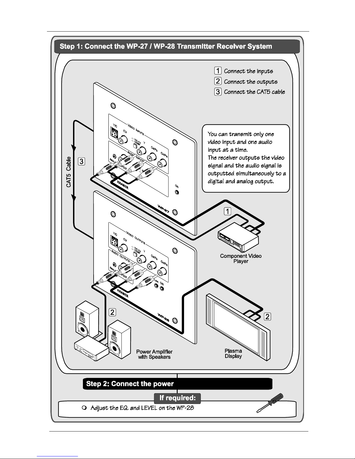
3.1 About the WP-27 / WP-28
The Kramer WP-27 and the WP-28 constitute a twisted pair transmitter and
receiver system for component/composite
1
or Y/C video, as well as stereo
analog / S/PDIF audio signals. Each unit can power or be powered by the other
unit over the same CAT5 cable.
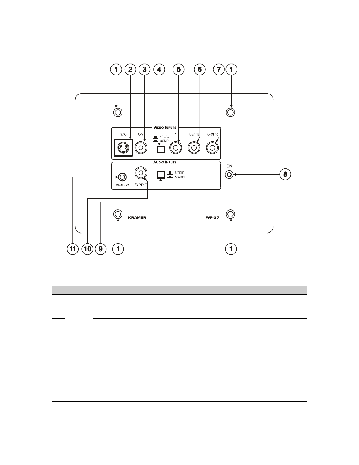
The WP-27 transmitter converts the selected
2
video and audio signals into a
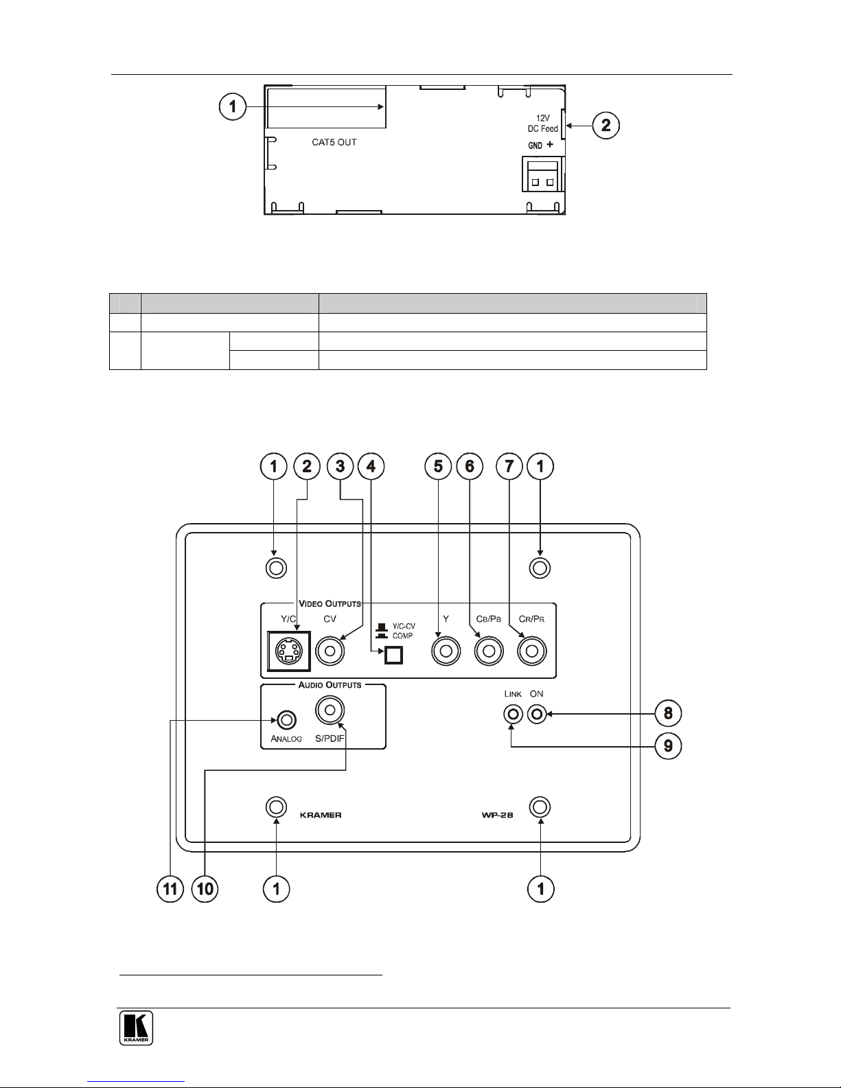
twisted pair signal and the WP-28 receiver decodes that signal back to its initial
stage. The WP-27 accepts either a component video, composite video or s-
Video source. The selected video source, as well as the selected audio source
3
is
transmitted to the WP-28, which outputs that source accordingly
4
.
If CV-Y/C is selected, the WP-27 accepts a CV
5
or Y/C
6
signal
7
and
transmits it over the CAT5 cable to the CV or Y/C output on the WP-28
receiver
If component video is selected
8
, the component video signal
7
is transmitted
over the CAT5 cable to the COMP output on the WP-28 receiver
If the ANALOG stereo audio source is selected via the AUDIO button, the
WP-27 converts it to a digital 48kHz 24 bit signal which is transmitted,
together with the video signal, over the CAT5 cable to the WP-28 receiver
If S/PDIF (digital audio) is selected via the AUDIO button, it is transmitted
together with the video signal over the CAT5 cable to the WP-28 receiver
1 Either s-Video or composite video (both inputs cannot be connected simultaneously)
2 Via two INPUT select buttons letting you choose the video signal input and the audio signal input
3 The audio signal is outputted to both outputs simultaneously
4 The WP-27 and WP-28 do not perform any video signal format conversion. A composite video source would need to be
routed to a composite video output or an s-Video source would need to be routed to an s-Video output. Similarly, a
component video source would need to be routed to a component video output
5 By connecting only a CV input and releasing the Y/C-CV COMP VIDEO INPUT button
6 By connecting only a Y/C input and releasing the Y/C-CV COMP VIDEO INPUT button
7 And audio signal
8 By pressing the Y/C-CV COMP VIDEO INPUT button