Overview
3
3 Overview
This section describes:
Using shielded twisted pair (STP)/unshielded twisted pair (UTP), see section 3.1
A summary of the VP-23N, see section 3.2
Recommendations for achieving the best performance, see section 3.3
The terminology used in this user manual, see section 3.4
3.1 Shielded Twisted Pair (STP) / Unshielded Twisted Pair (UTP)
The decision whether to use shielded twisted pair (STP) cable or unshielded
twisted pair (UTP) cable depends on the nature of the application.
It is recommended that in applications with high interference, shielded
twisted pair (STP) cable will give better results. However, the shield itself
does create a capacitance that degrades the frequency response of the
machines. For shorter distances, of 50m or so, shielded twisted pair (STP)
cable is preferred because it provides protection from interference
(degradation is non apparent).
For a long range application, unshielded twisted pair (UTP) cable is preferred.
However, the unshielded twisted pair (UTP) cable should be installed far away
from electric cables, motors etc., which are prone to create electrical interference.
Some Kramer twisted pair products include the Power Connect feature
1
. The
VP-23N does not have this feature.
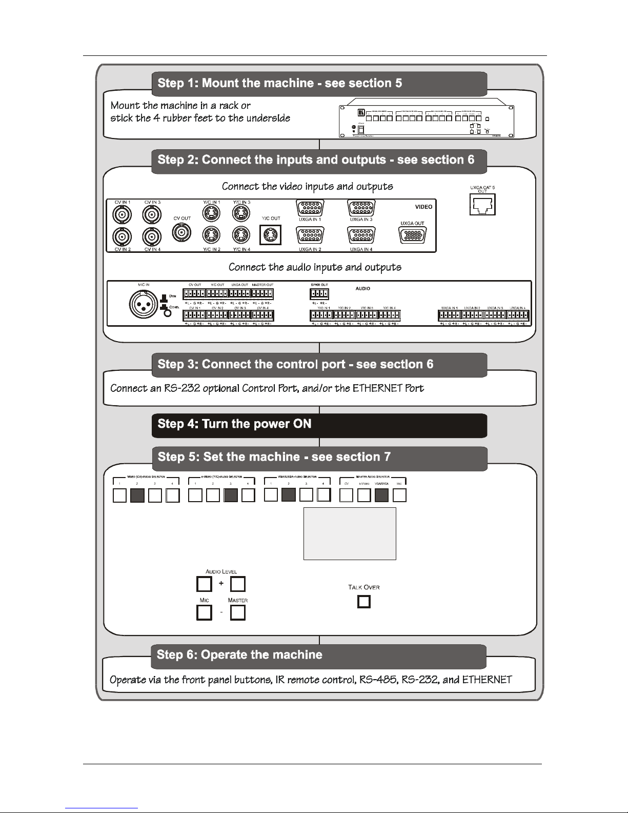
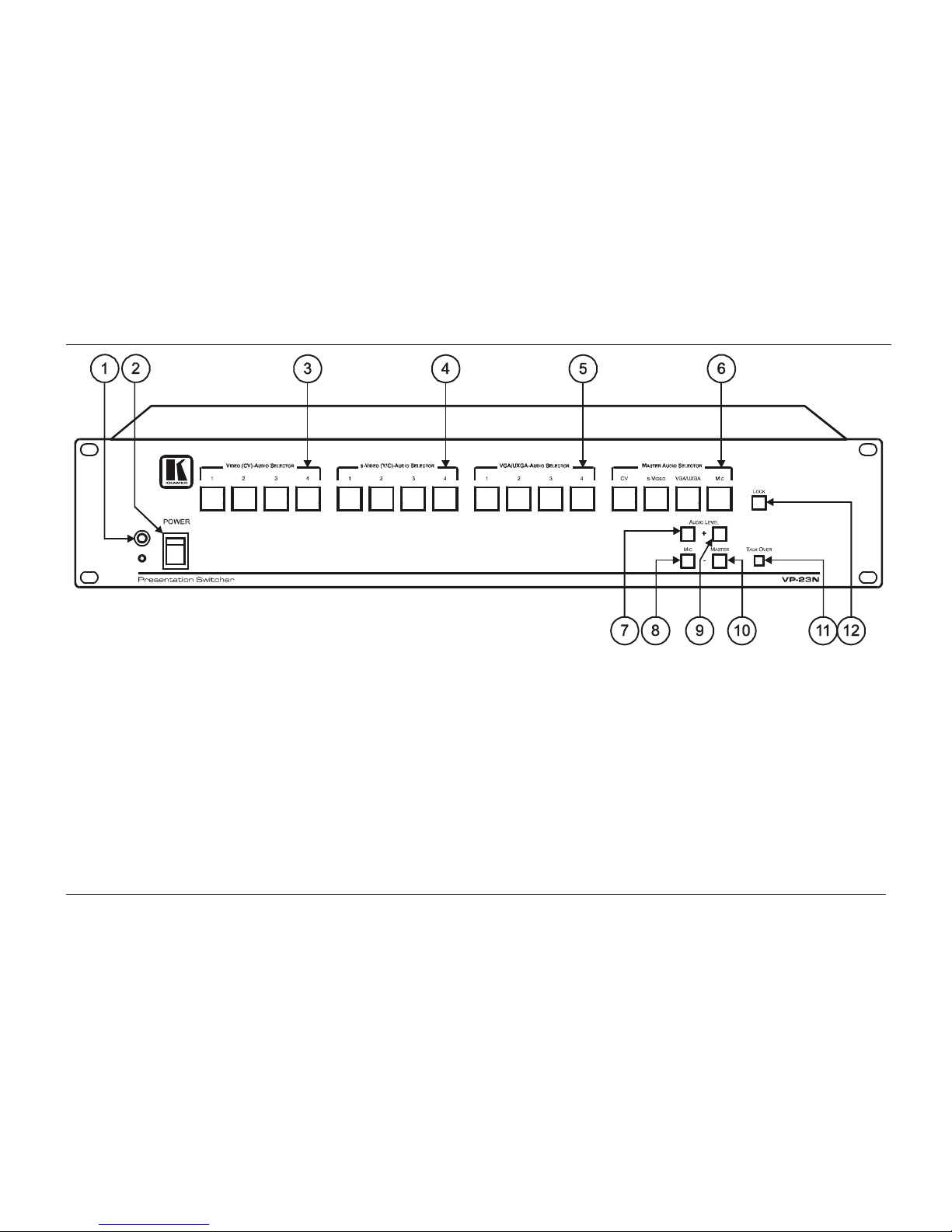
3.2 About the VP-23N
The VP-23N is a high quality one-box presentation switcher, which includes
three independent 4x1 audio/video switchers and a master audio switcher. It
combines the functions of a 4x1 switcher for composite video and audio, a
4x1 switcher for s-Video and audio, and a 4x1 switcher for computer graphics
(VGA/UXGA) signals with audio, as well as the master audio switcher that
routes one of the pre-selected audio inputs (from these three switchers) to two
separate outputs.
1 The Power Connect feature lets you power a transmitter / receiver system by connecting just one power adapter to either the
transmitter or the receiver. The other unit is fed over the same CAT5 cable. The Power Connect feature applies as long as the
CAT5 cable is heavy gauge cable (that is, it can carry power). The distance does not exceed 50 meters on standard cable. For
a distance of 100 meters, separate power supplies must be connected to the transmitter and to the receiver simultaneously,
unless using heavy gauge CAT5 cable