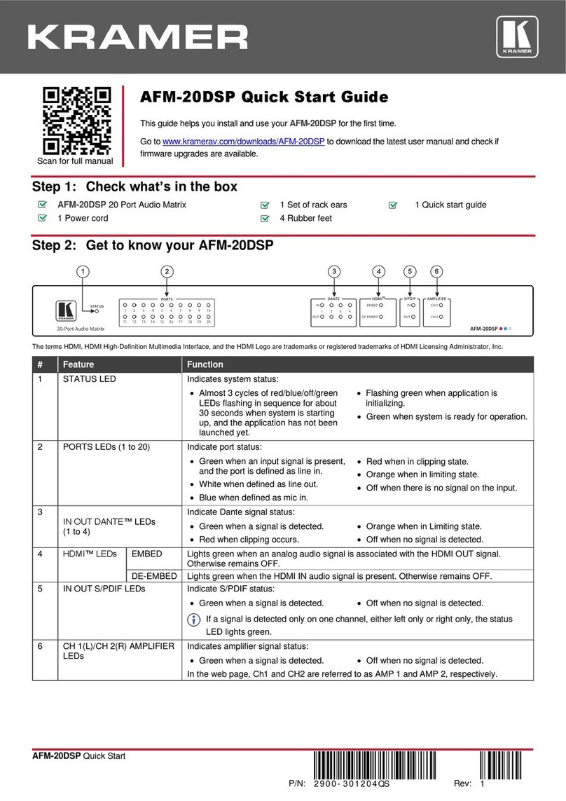
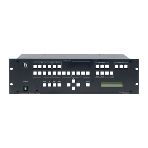
Program Button Press to disable/enable the program audio output
6 CONTROL SELECT Button Press to cycle
2
between the BASS, TREBLE, BALANCE and DELAY
3
7 IN LEVEL Button Press to select
2
the PROGRAM or the PREVIEW input audio level for
each program and preview channel
8 OUT LEVEL Button Press to select
2
the PROGRAM, the PREVIEW or the PHONES output
audio level
9 LOCK Button Press and hold to lock/unlock the front panel buttons
10 6.3mm Jack Connect to the headphones
11
PHONES
Button Press to select
2
which output (PROGRAM or the PREVIEW) to send to
the headphones
12 AUDIO LEVEL 7-segment Display Displays the numerical value of the CONTROL feature
4
13 + Button Press to increase the level
4
14 - Button Press to decrease the level
4
15 TAKE Button Press to swap the preview input with the program input
5
16 FADE Button Press to create a dissolved transition from the PREVIEW to the
PROGRAM output
17 AFV Button When pressed, the button is illuminated, and the audio channels
follow the video channels (on the VP-727xl or the VP-727)
Deselect AFV to switch the audio channels independently
18 RIGHT
19
INPUT RCA Connectors
LEFT
Connect to the unbalanced stereo audio source (from 1 to 8)
20 LEFT
21
PROGRAM RCA
Connectors RIGHT
Connect to an unbalanced stereo audio program acceptor
22 S/PDIF RCA Connector Connect to a digital audio acceptor
23 RIGHT
24
PREVIEW RCA
Connectors LEFT
Connect to an unbalanced stereo audio preview acceptor
25
OUTPUTS
PROGRAM Terminal Block
Connector
Connect to a balanced stereo audio program acceptor
DIP 8 to ON Operates the VP-727A with the VP-727xl (as slave baud rate 38,400)
DIP 7 to ON Operates the VP-727A with the VP-727 or the VP-727T (as chain baud
rate 115,200)
DIP 6 to ON For stand alone (baud rate 9,600)
DIPs 2, 3, 4and 5to OFF
26
SETUP DIPs
DIP 1to ON For the fade to follow the transition effect; set to OFF for separate fade
27 RS-485 Port Connects to the Kramer VP-727T or the VP-727xl (see section 6.4)
Pin G is for the Ground connection
6
; pins B (-) and A (+) are for
RS-485
28 RS-232 Connector
9-pin D-sub
connector connects to a PC or Remote Controller via a
null-modem connection
29 Power Connector with Fuse AC connector enabling power supply to the unit
1 From 1 to 8
2 The appropriate LED lights
3 The BASS, TREBLE and BALANCE levels are set for the PROGRAM output. The DELAY is set for each PROGRAM input
4 BASS, TREBLE, BALANCE, DELAY, audio input level (PREVIEW AND PROGRAM), and audio output level
(PREVIEW AND PROGRAM)
5 To reset the VP-727A to its factory default settings, turn the unit OFF, then turn it ON while pressing the TAKE button for about 2
seconds: The preview and program input is set to input 1, the input volume resets to 0dB, and the bass and treble levels reset to 0
6 The ground connection is sometimes connected to the shield of the RS-485 cable. However, usually the ground is not connected


