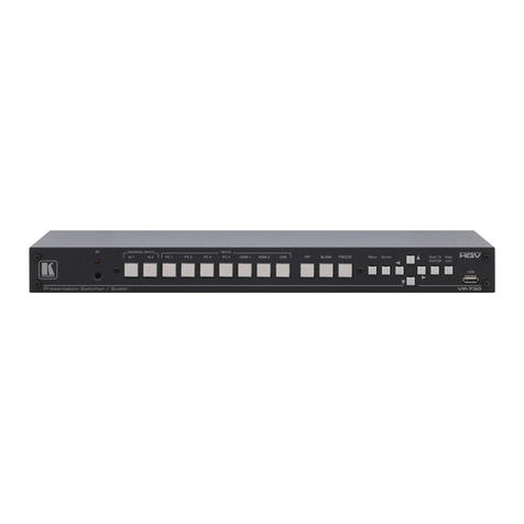
manuals.online logo
Brands
  1. Home
  2. •
  3. Brands
  4. •
  5. Kramer
  6. •
  7. Switch
  8. •
  9. Kramer VP-770 User manual

Kramer VP-770 User manual

VP-770 Quick Start
P/N:
2900- 301260QS
Rev:
6
Scan for full manual
VP-770 Quick Start Guide
This guide helps you install and use your VP-770 for the first time.
Go to www.kramerav.com/downloads/VP-770 to download the latest user manual and check if firmware
upgrades are available.
Step 1: Check what’s in the box
VP-770 Presentation Switcher/Scaler
1 Set of rack ears
4 Rubber feet
IR remote control transmitter with batteries
1 Power cord
1 Quick start guide
Step 2: Get to know your VP-770
Front Panel
#
Feature
Function
1
IR Receiver
Accepts IR remote commands
2
IR LED
Lights red when the unit accepts IR remote commands
3
INPUT
Selector
Buttons
HDMI™
Press to select the HDMI input (from 1 to 2)
4
PC
Press to select the computer graphics input (from 1 to 2)
5
COMP.
Press to select the component video input
6
CV
Press to select the composite video input (from 1 to 2)
7
DP
Press to select the Display Port input
8
PIP Button
Toggles the dual window mode (Picture-in-Picture) function
Note that while browsing the OSD menu in the dual window mode, a long press of the PIP button
will instantly toggle the window control (between Main and PiP)
9
BLANK Button
Press to toggle between a blank screen (blue or black screen) and the display
10
FREEZE Button
Press to freeze/unfreeze the output video image
11
Navigation
Buttons
/- Button
Press to move down the menu list and to decrease numerical values. When not within the OSD
menu mode, press to reduce the output volume
12
/MENU
Button
Press to access the OSD menu, exit the OSD menu and, when in the OSD menu, move to the
previous level in the OSD screen
13
/+
/VOLUME
Button
Press to move up the menu list values and to increase numerical values. When not within the
OSD menu mode, press to increase the output volume
14
/ENTER
Button
Press to access sub-menu items and select from several settings
15
RESET TO XGA/720P
Button
Press to reset the video output resolution to XGA or 720p and change the deep color settings to
Off on the output
Press and hold for about 3 seconds to toggle between reset to XGA and reset to 720p
16
PANEL LOCK Button
Press and hold for about 3 seconds to lock/unlock the front panel buttons
The terms HDMI, HDMI High-Definition Multimedia Interface, and the HDMI Logo are trademarks or registered trademarks of HDMI Licensing Administrator, Inc.
Rear Panel
#
Feature
Function
17
AUDIO IN
Unbalanced
Connectors
HDMI 3.5mm Mini
Jack
Connect to an unbalanced audio source for audio takeover of the HDMI 1 and HDMI 2
embedded audio.
18
PC 3.5mm Mini
Jack
Connect to the unbalanced audio of the computer graphics source (from 1 to 2).
19
DP 3.5mm Mini
Jack
Connect to the unbalanced audio source for analog audio takeover of the DisplayPort
embedded audio.
20
CV (L, R) RCA
Connect to the unbalanced stereo audio of the composite video source (from 1 to 2)
21
S/PDIF IN RCA
Connect to the digital audio source of the component video (Y, Pb, Pr)
22
MIC IN 3.5mm
Mini Jack
Connect to a microphone
23
COND/DYN MIC DIP-switch
Select between a condenser and a dynamic type microphone
24
S/PDIF OUT RCA Connector
Connect to a digital audio acceptor
25
LINE OUT (L, R) Terminal Block
Connector
Connect to the L and R unbalanced stereo audio acceptor
26
REMOTE IR 3.5mm Mini Jack
(opening)
Covered by a cap. The 3.5mm
connector at the end of the
internal IR connection cable fits
through this opening
Connects to an external IR receiver unit for controlling the machine via an IR remote
controller (instead of using the front panel IR receiver)
Optional. Can be used instead of the front panel (built-in) IR receiver to remotely
control the machine (only if the internal IR connection cable has been installed)
27
ETHERNET RESET Button
Press while turning power off and then on, to reset the Ethernet settings to their factory
default state
28
SPKR Terminal Block Connector
Connect to a balanced stereo audio acceptor (speakers)
29
VIDEO
INPUT
Connectors
HDMI
Connect to the HDMI source (from 1 to 2)
30
PC 15-pin HD
Connect to the computer graphics source (from 1 to 2)
31
Y RCA
Connect all three connectors to the component video source
32
PB RCA
33
PR RCA
34
CV RCA
Connect to the composite video source (from 1 to 2)
35
DISPLAYPORT
Connect to the DisplayPort source
36
VIDEO
OUTPUT
Connectors
PC 15-pin HD
Connect to a computer graphics acceptor
37
HDMI
Connect to an HDMI acceptor
38
DGKAT RJ-45
Connect to a DGKat receiver (for example, Kramer PT-572+)
39
RS-232 9-pin D-sub Port
Connect to the PC or other serial controller
40
ETHERNET Connector
Connects to the PC or other Controller through computer networking
41
REMOTE Terminal Block
Connectors
For remotely switching the inputs and PIP input via contact closure switches
42
Power Connector with Fuse
AC connector, enabling power supply to the unit
43
POWER Switch
Switch for turning the unit ON or OFF
Step 3: Mount VP-770
To rack mount the machine, attach both rack ears
(by removing the screws from each side of the
machine and replacing those screws through the
rack ears) or place the machine on a table.
•Ensure that the environment (e.g., maximum ambient temperature &
air flow) is compatible for the device.
•Avoid uneven mechanical loading.
•Appropriate consideration of equipment nameplate ratings should be
used for avoiding overloading of the circuits.
•Reliable earthing of rack-mounted equipment should be maintained.
Step 4: Connect inputs and outputs
Always switch OFF the power on each device before connecting it to your VP-770.
The Mic can be set to a condenser or
dynamic mic. When set to condenser,
48V of phantom power will be
available.
Wiring the RJ 45 Connectors
This section defines the TP pinout, using
a straight pin-to-pin cable with RJ 45
connectors.
EIA /TIA 568B
PIN
Wire Color
1
Orange / White
2
Orange
3
Green / White
For HDBT cables, it is recommended
that the cable ground shielding be
connected/soldered to the connector
shield.
4
Blue
5
Blue / White
6
Green
7
Brown / White
8
Brown
To achieve specified extension distances, use the recommended Kramer cables available at www.kramerav.com/product/VP-770.
Using third-party cables may cause damage!
Step 5: Connect power
Connect the power cord to VP-770 and plug it into the mains electricity.
Safety Instructions (See www.kramerav.com for updated safety information)
Caution:
•For products with relay terminals and GPI\O ports, please refer to the permitted rating for an external connection, located next to the terminal or in the User Manual.
•There are no operator serviceable parts inside the unit.
Warning:
•Use only the power cord that is supplied with the unit.
•Disconnect the power and unplug the unit from the wall before installing.
•Do not open the unit. High voltages can cause electrical shock! Servicing by qualified personnel only.
•To ensure continuous risk protection, replace fuses only according to the rating specified on the product label which located on the bottom of the unit.
Step 6: Operate VP-770
Enter the OSD menu via the MENU button on the front panel or the IR remote control transmitter. Select a menu item and set
parameters as required. Sub-menus include: Input, Audio, Process, Picture, Enhance, Scale, and Misc.
By default, the output resolution is set to Native, the VP-770 is triggered to read the EDID of the main display and change the output
resolution value according to the native resolution of the display.
If you cannot see any images, verify that the display, TV, or
projector is in good working order and is connected to the
VP-770. If you still don't see an image, press and hold the
RESET TO XGA/720P button for 2 seconds to reset the
output to XGA or 720p resolution.
Notable menu items include: Output Resolution, EDID Input Setting, HDCP Input Setting, Emergency Alert.
RS-232 Control / Protocol 3000
Baud Rate:
115,200
Parity:
None
Data Bits:
8
Command Format:
ASCII
Stop Bits:
1
Example (Set display mode to Picture in Picture): #Y0,110,1<CR>
Default Ethernet Parameters
Full Factory Reset
To reset the IP settings to the factory
reset values, power cycle the device
while holding in the Ethernet Reset
button, located on the rear panel of the
unit
Front panel
buttons
Turn power off. Turn power on again while holding the
RESET TO XGA/720p front panel button. The LEDs blink.
Full factory reset is complete once the LEDs cease to blink
and react normally
Note that full factory reset includes Ethernet reset as
well.
IP Address:
192.168.1.39
OSD
Factory Reset through the Misc. menu item
Subnet mask:
255.255.000.000
Web pages
Factory reset via the Device Settings embedded Web page
Default gateway:
000.000.000.000
Protocol 3000
Use "Factory" command or #Y 0,771,1<CR>
TCP Port#:
5000
UDP Port#:
50000
Maximum UDP Ports:
10
Maximum TCP Ports:
4
Web page password
1234
Step 7: Select an input via the contact closure remote control pins
Remote Control
To select input 3, momentarily connect the 3 PIN to the G PIN.
Remote Control
To select PIP input 8, connect the PIP PIN to the G PIN and, within 3 seconds,
momentarily connect the 8 PIN to the other G PIN.
Step 8: Control the display via HDKat
To activate port tunneling:
1. Set the dedicated port tunneling Ethernet connection port
type and port number through which the VP-770 will be
passing RS-232 signals (TCP and 5050, by default).
2. Use the UART command to set the communication
parameters (9600, 8, N and 1, by default).

Other manuals for VP-770

3

Other Kramer Switch manuals

Kramer VS-41H User manual

Kramer

Kramer VS-41H User manual

Kramer WP-211X User manual

Kramer

Kramer WP-211X User manual

Kramer VM-22H User manual

Kramer

Kramer VM-22H User manual

Kramer VP-551X User manual

Kramer

Kramer VP-551X User manual

Kramer ASPEN-1616UX User manual

Kramer

Kramer ASPEN-1616UX User manual

Kramer VP-730 User manual

Kramer

Kramer VP-730 User manual

Kramer VP-734 User manual

Kramer

Kramer VP-734 User manual

Kramer VS-120 User manual

Kramer

Kramer VS-120 User manual

Kramer VP-31KSi User manual

Kramer

Kramer VP-31KSi User manual

Kramer VS-21HDCP-IR User manual

Kramer

Kramer VS-21HDCP-IR User manual

Kramer FC-46xl User manual

Kramer

Kramer FC-46xl User manual

Kramer SWT3-21-H User manual

Kramer

Kramer SWT3-21-H User manual

Kramer VS-41HD User manual

Kramer

Kramer VS-41HD User manual

Kramer VP-725DSA User manual

Kramer

Kramer VP-725DSA User manual

Kramer VP-4x1 CS User manual

Kramer

Kramer VP-4x1 CS User manual

Kramer VM-218DTxr User manual

Kramer

Kramer VM-218DTxr User manual

Kramer VP-411DS User manual

Kramer

Kramer VP-411DS User manual

Kramer VS-401USB User manual

Kramer

Kramer VS-401USB User manual

Kramer VS-81HDxl User manual

Kramer

Kramer VS-81HDxl User manual

Kramer VP-725xl User manual

Kramer

Kramer VP-725xl User manual

Kramer WP-501 User manual

Kramer

Kramer WP-501 User manual

Kramer VA-1DVIN User manual

Kramer

Kramer VA-1DVIN User manual

Kramer SID-X2N User manual

Kramer

Kramer SID-X2N User manual

Kramer RC-10TBB User manual

Kramer

Kramer RC-10TBB User manual

Popular Switch manuals by other brands

Accton Technology ES4626 Management guide

Accton Technology

Accton Technology ES4626 Management guide

NVision NV5128 user guide

NVision

NVision NV5128 user guide

GeoVision GV-PoE user manual

GeoVision

GeoVision GV-PoE user manual

Compaq SW5425 specification

Compaq

Compaq SW5425 specification

CyberPower USB Hub quick start guide

CyberPower

CyberPower USB Hub quick start guide

Fujitsu Brocade 6545 Gen5 Hardware reference manual

Fujitsu

Fujitsu Brocade 6545 Gen5 Hardware reference manual

H3C S6800 Series Command reference

H3C

H3C S6800 Series Command reference

3Com 3CRDSF9PWR-US - OfficeConnect Managed Fast Ethernet PoE... user guide

3Com

3Com 3CRDSF9PWR-US - OfficeConnect Managed Fast Ethernet PoE... user guide

Cisco 3750 - Catalyst EMI Switch Hardware installation guide

Cisco

Cisco 3750 - Catalyst EMI Switch Hardware installation guide

EtherWAN EX48000A Series quick start guide

EtherWAN

EtherWAN EX48000A Series quick start guide

Zycoo CooVox-U20 Series user manual

Zycoo

Zycoo CooVox-U20 Series user manual

Encore ENUET-3USB user manual

Encore

Encore ENUET-3USB user manual

HPE FlexFabric 5940 SERIES Fundamentals Command Reference

HPE

HPE FlexFabric 5940 SERIES Fundamentals Command Reference

Spirax Sarco LCS3050 Installation and maintenance instructions

Spirax Sarco

Spirax Sarco LCS3050 Installation and maintenance instructions

Trilogy Communications Mentor CX user guide

Trilogy Communications

Trilogy Communications Mentor CX user guide

Master View CS-114A user manual

Master View

Master View CS-114A user manual

FXC FXC5016 user manual

FXC

FXC FXC5016 user manual

Panasonic ESP Series Specification sheet

Panasonic

Panasonic ESP Series Specification sheet

manuals.online logo
manuals.online logoBrands
  • About & Mission
  • Contact us
  • Privacy Policy
  • Terms and Conditions

Copyright 2025 Manuals.Online. All Rights Reserved.