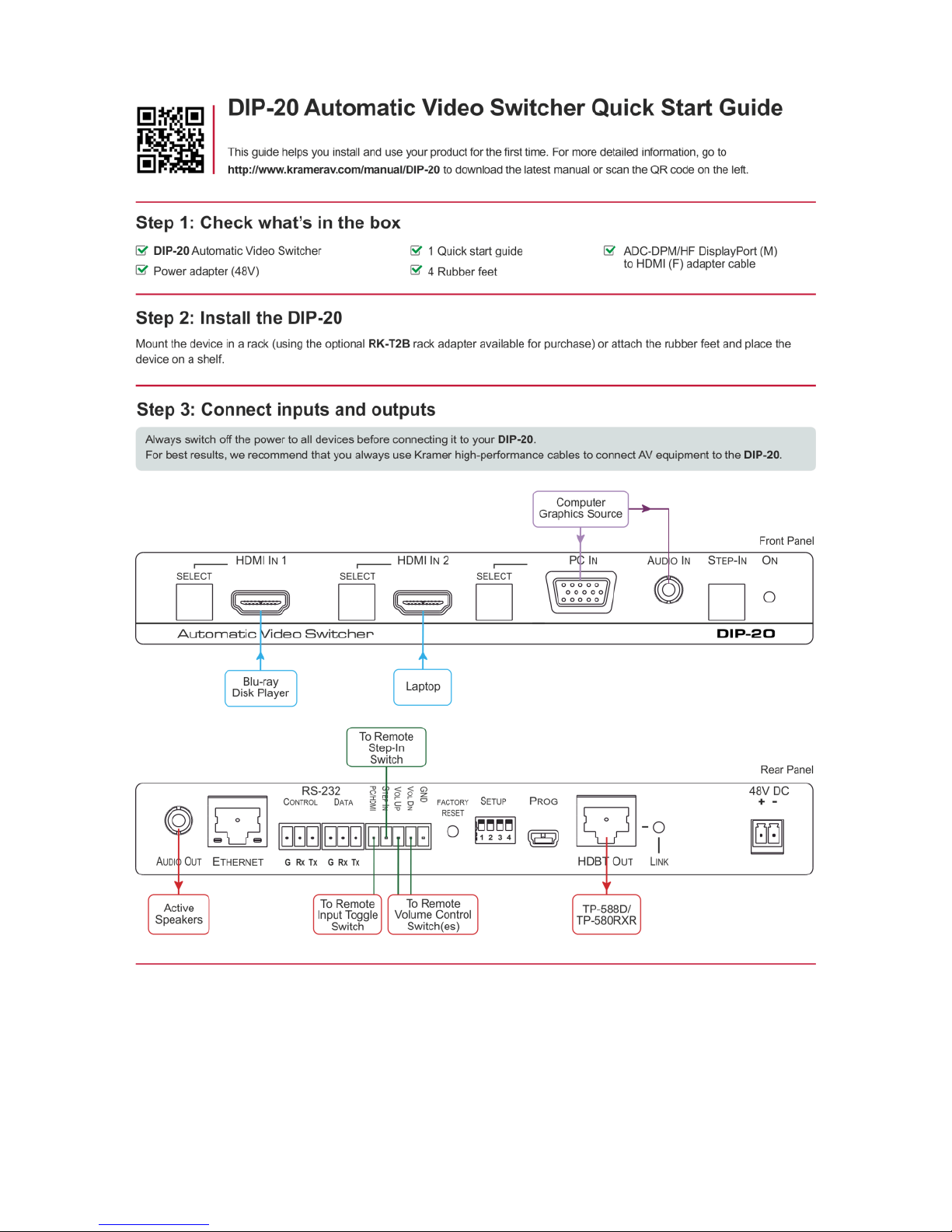
Kramer DIP-20 User manual

P/N: 2900-300490 Rev 3 www.kramerAV.com
USER MANUAL
MODEL:
DIP-20 Automatic Video Switcher


DIP-20 – Contents
i
Contents
1Introduction 1
2Getting Started 2
2.1 Achieving the Best Performance 2
2.2 Safety Instructions 2
2.3 Shielded Twisted Pair/Unshielded Twisted Pair 3
2.4Recycling Kramer Products 3
3Overview 4
3.1 About HDBaseT™ Technology 5
4Defining the Automatic Video Switcher 6
5Connecting the DIP-20 Automatic Video Switcher 8
5.1 Connecting the Remote Control Switches 10
5.2 Wiring the RJ-45 Connectors 11
6Principles of Operation 12
6.1 Input Selection 12
6.2 Signal Loss and Unplugged Cable Timeouts 13
6.3 Audio Signal Control 13
6.4 VGA Phase Shift 14
7Operating the DIP-20 15
7.1 Locking the EDID 15
7.2 Resetting the DIP-20 15
7.3 Analog Audio Output Volume Control 15
8Configuring the DIP-20 17
8.1 Setting the Configuration DIP-switch 17
8.2 Video Switching Timeouts 18
8.3 Using the Step-in Feature 18
9Operating the DIP-20 Remotely Using the Web Pages 19
9.1 Browsing the DIP-20 Web Pages 19
9.2 The Switching Page 23
9.3 The Device Settings Page 24
9.4 The Video and Audio Settings Page 27
9.5 The Authentication Page 28
9.6 The EDID Page 29
9.7 The About Us Page 30
10 Technical Specifications 32
10.1 Default IP Parameters 33
10.2 Default Logon Credentials 33
10.3 Supported Resolutions 33
11 Default EDID 35
11.1 HDMI 35
11.2 PC-UXGA 37
12 Protocol 3000 39
12.1 Kramer Protocol 3000 Syntax 39

ii
DIP-20 - Contents
Figures
Figure 1: DIP-20 Front Panel 6
Figure 2: DIP-20 Rear Panel 7
Figure 3: Connecting the DIP-20 8
Figure 4: Remote Switches Terminal Block 10
Figure 5: TP PINOUT 11
Figure 6: The Configuration DIP-switch 17
Figure 7: Entering Logon Credentials 19
Figure 8: The Default Page 20
Figure 9: The Main Switching Page 21
Figure 10: The Switching Page 23
Figure 11: The Device Settings Page 25
Figure 12: The Video and Audio Settings Page 27
Figure 13: The Authentication Page 28
Figure 14: The EDID Page 29
Figure 15: The About Us Page 31

DIP-20 – Introduction
1
1 Introduction
Welcome to Kramer Electronics! Since 1981, Kramer Electronics has been
providing a world of unique, creative, and affordable solutions to the vast range of
problems that confront video, audio, presentation, and broadcasting professionals
on a daily basis. In recent years, we have redesigned and upgraded most of our
line, making the best even better!
Our 1,000-plus different models now appear in 14 groups that are clearly defined
by function: GROUP 1: Distribution Amplifiers; GROUP 2: Switchers and Routers;
GROUP 3: Control Systems; GROUP 4: Format/Standards Converters; GROUP 5:
Range Extenders and Repeaters; GROUP 6: Specialty AV Products; GROUP 7:
Scan Converters and Scalers; GROUP 8: Cables and Connectors; GROUP 9:
Room Connectivity; GROUP 10: Accessories and Rack Adapters; GROUP 11:
Sierra Video Products; GROUP 12: Digital Signage; GROUP 13: Audio; and
GROUP 14: Collaboration.
Congratulations on purchasing your Kramer DIP-20 Automatic Video Switcher
which are part of the Kramer Audio Distribution System and are ideal for:
Display systems requiring simple, automatic input selection
Multimedia and presentation source selection
Video distribution in hotel rooms and schools

2
DIP-20 - Getting Started
2 Getting Started
We recommend that you:
Unpack the equipment carefully and save the original box and packaging
materials for possible future shipment
Review the contents of this user manual
Go to http://www.kramerav.com/downloads/DIP-20 to check for up-to-
date user manuals, application programs, and to check if firmware
upgrades are available (where appropriate).
2.1 Achieving the Best Performance
To achieve the best performance:
Use only good quality connection cables (we recommend Kramer high-
performance, high-resolution cables) to avoid interference, deterioration in
signal quality due to poor matching, and elevated noise levels (often
associated with low quality cables)
Do not secure the cables in tight bundles or roll the slack into tight coils
Avoid interference from neighboring electrical appliances that may adversely
influence signal quality
Position your DIP-20 Automatic Video Switcher away from moisture,
excessive sunlight and dust
This equipment is to be used only inside a building. It may only be
connected to other equipment that is installed inside a building.
2.2 Safety Instructions
Caution:
There are no operator serviceable parts inside the unit
Warning:
Use only the power cord that is supplied with the unit
Warning:
Do not open the unit. High voltages can cause
electrical shock! Servicing by qualified personnel only
Warning:
Disconnect the power and unplug the unit from the
wall before installing

DIP-20 – Getting Started
3
2.3 Shielded Twisted Pair/Unshielded Twisted Pair
Kramer engineers have developed special twisted pair cables to best match our
digital twisted pair products; the Kramer BC-HDKat6a (CAT 6 23 AWG) HDBaseT
certified, and the Kramer BC-DGKat7a23 (CAT 7a 23 AWG) cables. These
specially built cables significantly outperform regular CAT 6 and CAT 7a cables.
2.4 Recycling Kramer Products
The Waste Electrical and Electronic Equipment (WEEE) Directive 2002/96/EC
aims to reduce the amount of WEEE sent for disposal to landfill or incineration by
requiring it to be collected and recycled. To comply with the WEEE Directive,
Kramer Electronics has made arrangements with the European Advanced
Recycling Network (EARN) and will cover any costs of treatment, recycling and
recovery of waste Kramer Electronics branded equipment on arrival at the EARN
facility. For details of Kramer’s recycling arrangements in your particular country
go to our recycling pages at http://www.kramerelectronics.com/support/recycling/.

4
DIP-20 - Overview
3 Overview
The DIP-20 accepts an HDMI and PC graphics video input, an Ethernet signal,
serial data, and an unbalanced stereo audio input (which is embedded into the
output signal), and transmits the signal via HDBaseT (Twisted Pair) cable to a
compatible receiver (for example, the TP-588D or the TP-580RXR). The
DIP-20 is a PoE (Power over Ethernet) provider and can power compatible PoE
acceptors, (for example, the TP-588D and the TP-590RXR).
The DIP-20 provides a range of up to 130m (427ft) in normal mode for
1080p@60Hz @36bpp, and 100m (328ft) for 4K @30Hz. When using an extended
range receiver and BC−HDKat6a cables, the range is up to 180m (590ft) for
1080p@60Hz @24bpp. To use the DIP-20 in extended range mode you must edit
the EDID.
For optimum range and performance, use Kramer's BC−HDKat6a and
BC−DGKat7a23 shielded twisted pair (STP) cables. Note that the
transmission range depends on the signal resolution, graphics card and
display used. The distance using non-Kramer CAT 6 and CAT 7 cables
may not reach these ranges.
The DIP-20 Automatic Video Switcher features:
Support for 4K UHD (data rate of up to 10.2Gbps)
Automatic live input detection based on video clock presence
Automatic input selection based on priority selection or last connected input
Manual input selection
Automatic analog audio detection and embedding
Power over Ethernet which passes electrical power along with data over
Ethernet cabling. This allows a single cable to provide both data connection
and electrical power to compatible devices
Control via Kramer Protocol 3000 and embedded Web pages over a LAN
HDTV support
HDMI with Deep Color, x.v.Color™ and 3D
HDCP compliancy—works with sources that support HDCP repeater mode

DIP-20 – Overview
5
I-EDIDPro™ Kramer Intelligent EDID Processing™ – Intelligent EDID
handling & processing algorithm ensures Plug and Play operation for HDMI
systems
A lockable EDID
Step-in control when connected to a device that provides step-in support
Remote control via contact-closure switches
Equalization and re-clocking of the data
Support for digital audio formats
3.1 About HDBaseT™ Technology
HDBaseT™ is an advanced, all-in-one connectivity technology (supported by the
HDBaseT Alliance). It is particularly suitable in the ProAV –and also the home –
environment as a digital networking alternative, where it enables you to replace
numerous cables and connectors by a single LAN cable used to transmit, for
example, uncompressed, full high-definition video, audio, IR, as well as various
control signals.
The products described in this user manual are HDBaseT certified.

6
DIP-20 - Defining the Automatic Video Switcher
4 Defining the Automatic Video Switcher
Figure 1 defines the front panel of the DIP-20.
Figure 1: DIP-20 Front Panel
#
Feature
Function
1
HDMI IN 1
SELECT Button
Press to select the HDMI 1 input.
When HDMI 1 is selected, the button:
Lights red when analog Audio In audio is
selected
Lights green when embedded audio is
selected
2
HDMI 1 Connector
Connect to the first HDMI source
3
HDMI IN 2
SELECT Button
Press to select the HDMI 2 input.
When HDMI 2 is selected, the button:
Lights red when analog Audio In audio is
selected
Lights green when embedded audio is
selected
4
HDMI 2 Connector
Connect to the second HDMI source
5
PC IN
SELECT Button
Press to select the PC graphics input.
When PC graphics is selected, the button:
Lights red when analog Audio In audio is
selected
Lights green when embedded audio from
embedded HDMI is selected, (see
Section 8.1)
6
PC Graphics 15-pin
HD Connector
Connect to the PC graphics source, (for
example, a laptop)
7
AUDIO IN 3.5mm Mini Jack
Connect to the unbalanced, stereo audio
source, (for example, the audio output of the
laptop)
8
Step-In Button
Press to take control of the input that this
device is connected to on a compatible
switcher
9
ON LED
The LED indicates the following:
Lights green—power is provided by a
power adapter
Lights red—power is provided via PoE to
another device

DIP-20 – Defining the Automatic Video Switcher
7
Figure 2 defines the rear panel of the DIP-20.
Figure 2: DIP-20 Rear Panel
#
Feature
Function
1
AUDIO OUT 3.5mm Mini
Jack
Connect to the unbalanced, stereo audio
acceptor, (for example, active speakers)
2
ETHERNET RJ-45
Connector
Connect to the LAN, (Ethernet traffic or PC
controller)
3
RS-232
CONTROL 3-
pin Terminal
Block
Connect to a serial controller or PC
4
DATA 3-pin
Terminal
Block
Connect to a serial data source or acceptor,
(RS-232 data over HDBT)
5
PC/HDMI Remote Toggle
Switch Terminal Block
Connect to a remote switch to toggle between
the PC graphics and HDMI inputs
6
Remote Contact-closure 4-
pin Terminal Block
Connect to remote momentary switches to
control input selection, step-in, and volume up
and down
7
FACTORY RESET Button
Short press to reboot, long press to reset the
device to factory default parameters
8
SETUP 4-way DIP-switch
Switches for setting the device behavior, (see
Section 8.1)
9
PROG Mini USB
Connector
Connect to a PC to perform a firmware upgrade
10
HDBT OUT RJ-45 TP
Connector
Connect to a compatible HDBT TP switcher or
receiver (for example, the TP-588D/TP-580Rxr)
11
LINK LED
Lights green when there is a valid HDBT link
12
48VDC Connector
Connect to the supplied power adapter
13
STEP IN Remote Toggle
Switch Terminal Block
Connect to a remote switch to activate the step
in function

8
DIP-20 - Connecting the DIP-20 Automatic Video Switcher
5 Connecting the DIP-20 Automatic Video
Switcher
Always switch off the power to each device before connecting it to
your DIP-20. After connecting your DIP-20, connect the power to
each of them and then switch on the power to each device.
Figure 3: Connecting the DIP-20

DIP-20 - Connecting the DIP-20 Automatic Video Switcher
9
You do not have to connect all the inputs and outputs, connect only
those that are required.
To connect the DIP-20 as illustrated in Figure 3:
1. Connect an HDMI source, (for example, a Blu-ray disk player) to the
HDMI IN 1 input.
2. Connect a PC graphics source, (for example, a laptop) to the PC In input.
3. Connect an unbalanced stereo audio source, (for example, the audio
output from the laptop) to the AUDIO IN 3.5mm mini jack.
4. Connect the HDBT OUT RJ-45 connector on the rear panel of the
DIP-20 to an HDBT-compatible receiver (for example, the TP-588D or
TP-580Rxr).
5. Connect the HDMI output of the HDBT acceptor, (for example, the
TP-588D or TP-580Rxr) to the HDMI acceptor, (for example, a projector).
6. Connect the AUDIO OUT 3-pin terminal block on the rear panel of the
DIP-20 to the unbalanced, stereo audio acceptor, (for example, active
speakers).
7. Connect the STEP IN 2-way terminal block to a momentary, contact-
closure switch, (see Section 5.1).
8. Connect the PC/HDMI 2-way terminal block to a momentary, contact-
closure switch, (see Section 5.1).
9. Connect the RS-232 DATA 3-pin terminal block to the device to be
controlled, (for example, the projector connected in step 5).
10. Connect the power adapter to the DIP-20 and to the mains power, (not
shown in Figure 3).

10
DIP-20 - Connecting the DIP-20 Automatic Video Switcher
5.1 Connecting the Remote Control Switches
You can connect remote, momentary-contact contact-closure switches to the
terminal block on the rear panel of the DIP-20 to control the device.
Figure 4 illustrates the connections from the terminal block to the contact-
closure switches.
Figure 4: Remote Switches Terminal Block
#
Feature
Function
1
PC/HDMI—input
selection/VGA phase shift
adjustment
Short press—Input toggle
Long press—Adjusts the VGA phase shift, (see
Section 6.4)
2
STEP IN
Activates the step-in function if relevant
3
VOL UP—analog audio output
volume increase control, (see
Section 7.3)
Short press—Increases the volume one step
Long press—Increases the volume from 0% to 100%
in 10 seconds
4
VOL DN—analog audio output
volume decrease control, (see
Section 7.3)
Short press—Decreases the volume one step
Long press—Decreases the volume from 100% to 0%
in 10 seconds
G
GND
Connect to the common side of the switches

DIP-20 - Connecting the DIP-20 Automatic Video Switcher
11
5.2 Wiring the RJ-45 Connectors
This section defines the TP pinout, using a straight pin-to-pin cable with RJ-45
connectors.
EIA /TIA 568B
Figure 5: TP PINOUT
PIN
Wire Color
1
Orange / White
2
Orange
3
Green / White
4
Blue
5
Blue / White
6
Green
7
Brown / White
8
Brown

12
DIP-20 - Principles of Operation
6 Principles of Operation
The DIP-20 selects video and audio inputs based on the rules described below.
6.1 Input Selection
The video mode selection is set by the DIP-switches (see Section 8.1) to either
of the following modes:
Manual
Auto—Last connected or priority mode
In manual mode switching occurs whether or not there is a live signal present
on the input. You select manually select an input using any of the following
methods:
Front panel buttons
Remote input selection switches
RS-232 control
The Web pages
In auto mode, the switching selection is performed based on either last
connected or priority input.
In last connected mode, if the signal on the current input is lost, the DIP-20
automatically selects the last connected input, (the delay depending on a
configurable timeout).
In priority mode, when the input sync signal is lost for any reason, the input with
a live signal and next in priority is selected automatically, (the delay depending
on the configurable signal-lost timeout). This priority is configurable; the default
setting is HDMI 1 →HDMI 2 →PC.
Note: In both last connected and priority modes, manually selecting an input
(using the remote input selection switches or any of the above methods)
overrides automatic selection.

DIP-20 - Principles of Operation
13
6.2 Signal Loss and Unplugged Cable Timeouts
In both last connected and priority modes, when the input signal sync is lost
(but the cable is not removed) there is a default delay (ten seconds for video,
not applicable to the PC input, and five seconds for analog audio) before
another input is automatically selected. When an input cable is removed, there
is a delay before automatic switching takes place.
Both timeouts are configurable, (see Section 8.1).
Note: Analog audio is not output when there is no display connected. If a
display is connected analog audio is output even in the absence of a video
signal.
6.3 Audio Signal Control
The Option DIP-switches 3 and 4 (see Section 8.1) control the manner in which
audio is handled.
The following table describes which audio signal is embedded in the output.
Selected
Video Input
HDMI
Embedded
Audio Detected
Analog
Audio In
Detected
DIP-switch
3
DIP-switch
4
Audio on HDBT
Output
VGA
N/A
Yes
N/A
N/A
Analog Audio In
VGA
N/A
No
N/A
N/A
No audio
HDMI
N/A
N/A
Manual
Embedded
Embedded HDMI
audio
HDMI
N/A
N/A
Manual
Analog
Analog Audio In
HDMI
Yes
No
Auto
N/A
Embedded HDMI
audio
HDMI
Yes
Yes
Auto
Embedded
Embedded HDMI
audio
HDMI
Yes
Yes
Auto
Analog
Analog Audio In
HDMI
No
Yes
Auto
N/A
Analog Audio In
HDMI
No
No
Auto
N/A
No audio
When there is an audio signal but no video signal the output is a black video
pattern in conjunction with the external analog Audio In signal.

14
DIP-20 - Principles of Operation
Note: The default timeout for audio switching when the input signal is lost is
five seconds. This can be changed using either P3000 commands or the Web
pages.
6.4 VGA Phase Shift
To minimize phase on the input VGA signal, the VGA sampling phase can be
shifted using the following methods:
A long press on the PC IN select button on the front panel.
Each long press steps the phase shift up one step, starting from 0 and
going to 31. When set to 31, another long press steps the shift to 0
A remote, contact-closure switch connected to pins 1 and G of the
Remote terminal block.
Each long press steps the phase shift up one step, starting from 0 and
going to 31. When set to 31, another long press steps the shift to 0
Using the Web pages, (see Section 9.1)
Protocol 3000 commands over RS-232 (see Section 12)

DIP-20 - Operating the DIP-20
15
7 Operating the DIP-20
The DIP-20 can be operated using any of the following methods:
Front panel buttons
Protocol 3000 command, (see Section 12)
Remote contact-closure switch, (see Section 5.1)
Web pages, (see Section 9)
7.1 Locking the EDID
To prevent the stored EDID (either default or read from a device) from being
overwritten, either send a Protocol 3000 command or use the Web pages.
7.2 Resetting the DIP-20
To perform a soft reset of the DIP-20:
Briefly press the Reset button.
The device resets
To reset the DIP-20 to factory default parameters:
Press and hold the Reset button for five seconds.
The device is reset to factory default parameters
7.3 Analog Audio Output Volume Control
The analog audio output volume can be controlled using the Web pages, (see
Section 9.1) or via the remote, contact-closure switches connected to pins 3
and 4 of the Remote terminal block, (see Section 5.1).
The up/down volume steps per press are detailed in the table below.
Other manuals for DIP-20
3
Table of contents
Other Kramer Switch manuals

Kramer
Kramer DIP-31M User manual

Kramer
Kramer VS-21H-IR User manual

Kramer
Kramer VS-21H-IR User manual

Kramer
Kramer VP-771 User manual

Kramer
Kramer VP-211N User manual

Kramer
Kramer VS-21DVI User manual

Kramer
Kramer VS-41H2 User manual

Kramer
Kramer VM-3H2 User manual

Kramer
Kramer KIT-400 User manual

Kramer
Kramer VP-730 User manual

Kramer
Kramer RC-21TB User manual

Kramer
Kramer Wall Plate Series User manual

Kramer
Kramer 6241HD User manual

Kramer
Kramer WP-211T User manual

Kramer
Kramer VS-41H User manual

Kramer
Kramer DIP-22 User manual

Kramer
Kramer VP-720DS User manual

Kramer
Kramer VS-211XS User manual

Kramer
Kramer VP-211DS User manual

Kramer
Kramer VS-2DVA User manual