krispol STARCUS K06 User manual

K06/K10
GB SE
PL Wszelkie prawa do przedruku lub kopiowania są zastrzeżone - dozwolone jedynie za zgodą producenta.
EN All rights to reprint or copy this document are reserved - these activities are allowed only with the permission of the manufacturer.
DE Druck und Vervielfältigung urheberrechtlich verboten – Die Nutzung ist nur mit ausdrücklicher Zustimmung des Herstellers zulässig.
CZ Veškerá práva k dotisku nebo kopírování jsou vyhrazená - povoleny jsou pouze se souhlasem výrobce.
SK Všetky práva na dotlač alebo kopírovanie sú vyhradené - povolené sú iba so súhlasom výrobcu.
DK Alle rettigheder forbeholdt – genoptryk el. kopiering må udelukkende finde sted mod producentens samtykke.
SE Rätten till nytryck eller kopiering är förbehållen - endast med tillverkarens tillstånd.
RU Все права на перепечатывание или копирование защищены - это разрешается исключительно с согласия производителя.
RO Toate drepturile de retipărire sau copiere sunt rezervate - admise doar cu permisiunea producătorului.
FR Droits d’impression ou de copie réservés – soumis au consentement du fabricant.
VIII-2020
DRIVE INSTALLATION MANUAL BRUKSANVISNING FÖR DRIVANORDNINGEN

23
Table of contents
e declaration of incorporation 2
1. Introduction 24
2. Marking of the product and its intended use 24
3. General information on installing 25
4. Installation safety and warnings 25
4.1. General rules 25
4.2. Warning and safety signs 26
5. Structure of the drive 27
5.1. Technical data 27
5.2. Construction of the drive and its components 27
5.3. Additional equipment 29
5.4. Installation dimensions 29
5.5. Hazardous areas 29
6. Assembling the drive with the garage doors 30
6.1. Tools for assembly 30
6.2. List of cables 30
6.3. Preliminary checks before assembly 30
6.4. Installation 31
6.5. Electrical connections 33
7. Programming 34
7.1. Final inspection and start-up 35
8. Commissioning 36
9. Replacing components 36
9.1. Replacing the fuse 36
9.2. Replacing the batteries in the remote control 36
9.3. Replacing the drive 37
10. Troubleshooting 37
11. Dismantling and disposal 37
12. Guarantee Card 37
13. Report book 37
EN

24
1. Introduction
2. Marking of the product and its intended use
is manual is intended for use only by qualified installers.
e installer who installs the drive, together with the garage doors is responsible for its proper installation and adjustment to ensure
proper operation.
e owner of the garage door, after its installation, is provided with:
• user manual
• maintenance manual
• Report Book
• Declaration of Conformity signed by an authorized installer (after functional tests of the garage doors with the drive
and making sure that the drive, control and all protection devices work properly).
e garage doors with the drive may not be used until they are commissioned as described in chapter 8: „Commissioning”.
In case of any doubt, do not start the assembly, but contact the manufacturer [„Krispol”] to obtain clarifications or local servicing team.
Product identification data is presented on the nameplate attached to the drive head. e drive is available in two versions:
STARCUS K06 and STARCUS K10.
It is efficient drive with a modern design for automatic operation of sectional garage doors.
It is available in two power versions, suitable for garage doors with a maximum area of 8 m2or 12.5 m2.
It is equipped with:
• an amperometric system for obstacle detection - after detecting an obstacle, the drive stops the door and reverses its motion,
• a function of soft start and soft stop, preventing strong jerks during opening and closing the door,
• a built-in LED lamp to light the opened garage (three-minute operation),
• overload protection,
• an option of programming the automatic closing,
• LED display for easy programming of functions.
ere is a possibility of connecting:
• a micro-switch of service door, which blocks the movement of the door after opening,
• photocells and a function of external emergency disconnection of the drive in case of power failure.
e content of the basic set:
• the drive with a built-in 433.92 MHz radio set,
• 3-channel transmitter,
• rail with a belt or chain (optional)
• mounting elements.
A detailed description of the components is in presented in section 5.2 (see p. 25).
e drive should be installed at a minimum height of 2.5 m above the floor or access level.
e drive can not be used with door having openings with a diameter greater than 50 mm, edges or protruding parts that may be used
for standing or gripping.
e drive is suitable for sectional garage doors with the following parameters:
Wn - installation depth in the garage door with a drive
A - 600N, 3100mm
B - 600N, 4000mm
C - 1000N, 3100mm
D - 1000N, 4000mm
EN
GUIDING N, L, SL, NH, E
GUIDING H
Wn height\width 2200 2300 2400 2500 2600 2750 3000 3250 3500 3750 4000 4250 4500 4750 5000 5250 5500 5750 6000
3160 2000
2125
4060
2250
2375
2500
2625
2750
C
A
B D
Wn height\width 2200 2300 2400 2500 2600 2750 3000 3250 3500 3750 4000 4250 4500 4750 5000 5250 5500 5750 6000
3160
2000
2125
2250
4060
2375
2500
2625
2750
2875
3000
A C
BD

25
Any connection of additional elements, programming remote controls, and installation of the drive are described in the following part of
the installation manual.
e drive uses electricity and in case of power failure from the mains, it may be unlocked and the door may be operated manually. ere is
also the possibility of installing an emergency battery, which would allow operation of the drive in case of a power failure from the mains.
e drive with the sectional garage door is designed for use in vehicular and pedestrian applications. It should be installed in residential
buildings and it is intended solely for use in individual households. It should not be installed in doors installed in public buildings.
It is unacceptable to install these doors in industrial and commercial facilitates.
e drive is designed for indoor operation. It is prohibited to install the device outdoors and in areas with potentially explosive atmospheres
or in those with the presence of flammable liquids, gases or dust. Do not expose the drive to rain or moisture.
e motorized garage door may be fixed to the support structure of an apartment building.
e installation base should be as follows:
• walls - dry and level surface with adequate strength made in accordance with binding building regulations,
• metal structures - correct design and sufficient strength. Depending on the installation base, use the following items:
• dowels - for the base made of reinforced concrete or solid brick,
• self-tapping screws or bolts - for steel structures,
• dowels for cavity bricks and aerated concrete - for a base made of cavity bricks, aerated concrete or similar material.
e precise types and size of fixing elements are determined individually with each customer.
Providing the appropriate fixing elements is the responsibility of the customer ordering the garage doors.
e support structure must ensure proper drilling of holes for fixing elements.
e place for installing and operating the motorized garage door should be properly lit and should be selected to ensure safe operation
of the garage doors. e owner of the garage door shall be responsible for ensuring these conditions.
• Mounting components of the drive are supplied with the drive.
• It is unacceptable to use other mounting elements than those included in the package.
• All electrical connections must be made after the power supply is cut off and with any potential emergency battery disconnected.
Compliance with the installation procedure described in this manual will ensure the smooth and safe operation of the door with the drive.
Improper installation and operation may lead to serious personal injury and property damage.
Before starting the installation process, please read thoroughly the manual. It is unacceptable to make modifications that are not listed
in this document. It is prohibited to install the drive for other purposes than those specified in this manual. It is obligatory to use only the
included tools and components for fixing and always use the provided fasteners (screws, dowels, screws, nuts) appropriate to the type of
fixing and loads generated by the door with the drive.
Before starting the assembly read this manual and observe the following rules for eliminating the risks and take appropriate precautions.
For installation work, use personal protective equipment PPE and technical measures to ensure the safety of yourself, third parties, property
and the environment.
WARNING: Automatic drive.
WARNING! Any deviations from requirements for fixing elements are forbidden,
as they may create risks for future users!
WARNING: Important safety instructions. Follow all instructions, as improper
installation may lead to serious injury.
3. Installation information
4. Installation safety and warnings
4.1. General rules
EN

26
Improper installation and operation may lead to serious personal injury and property damage.
• Installation should be performed by trained assembly team with appropriate qualifications and authorized by KRISPOL.
• Adhere to the applicable safety regulations. Particular attention should be paid to the safety when working with electrical devices and
at heights.
• e assembly area should be properly marked and secured.
• Features of the assembly surface are described in sec. 3.
• During the assembly works, remember to:
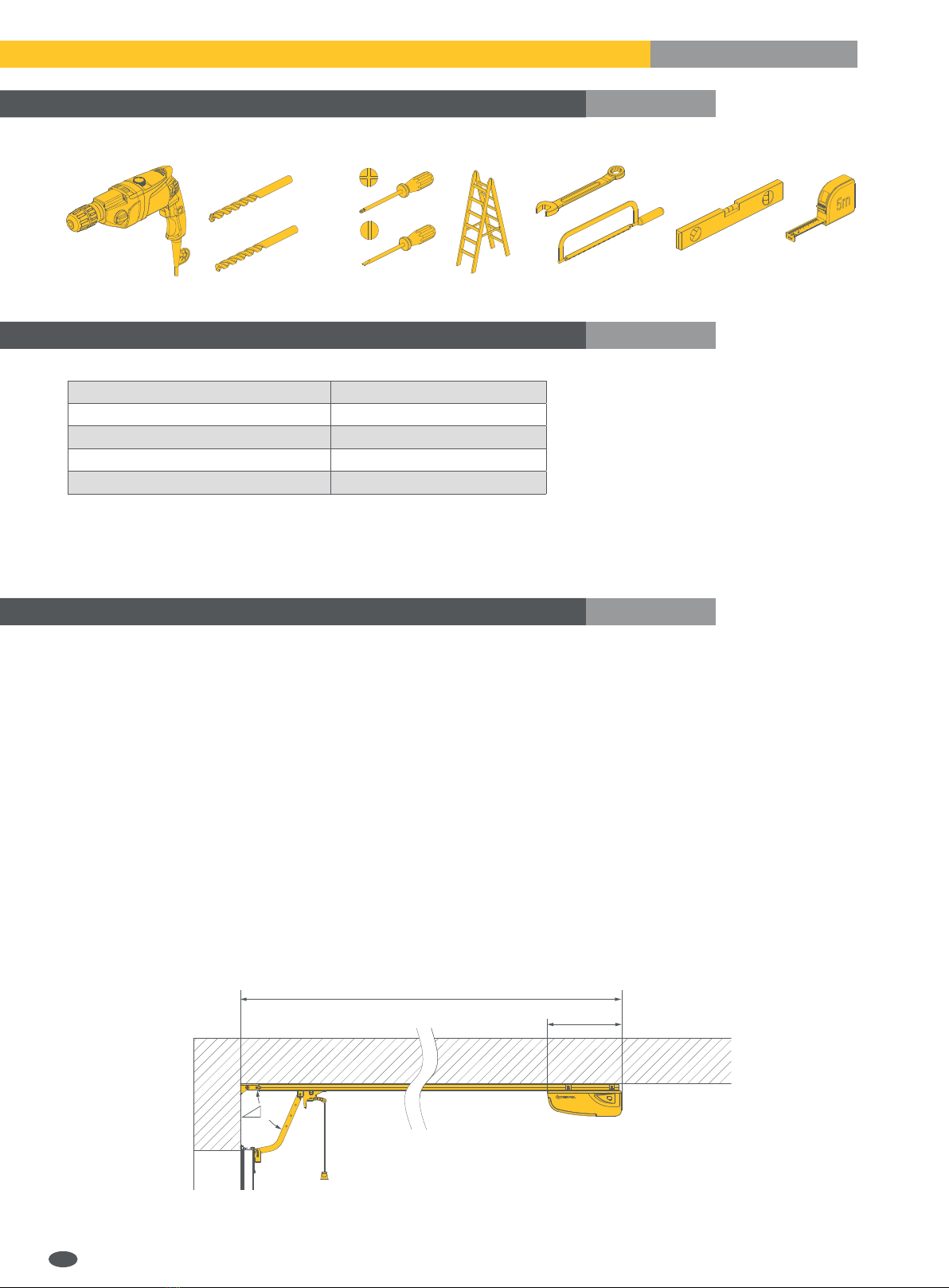
- assemble materials and tools necessary to perform the work (they are listed in section „Tools and materials”);
- use only original manufacturer’s parts;
- use stable structures for work at height;
- adequately protect face and hands during drilling;
- prevent the presence of children near the place of installation works;
- remove debris and other obstacles that could hinder the movement of the door, before starting it;
- install a device for manual lock releasing at a height of not more than 180 cm;
- install the external control unit at a minimum height of 150 cm, in the location ensuring the visibility of the whole area of
movement, but not colliding with the movement of the garage doors - away from moving parts.
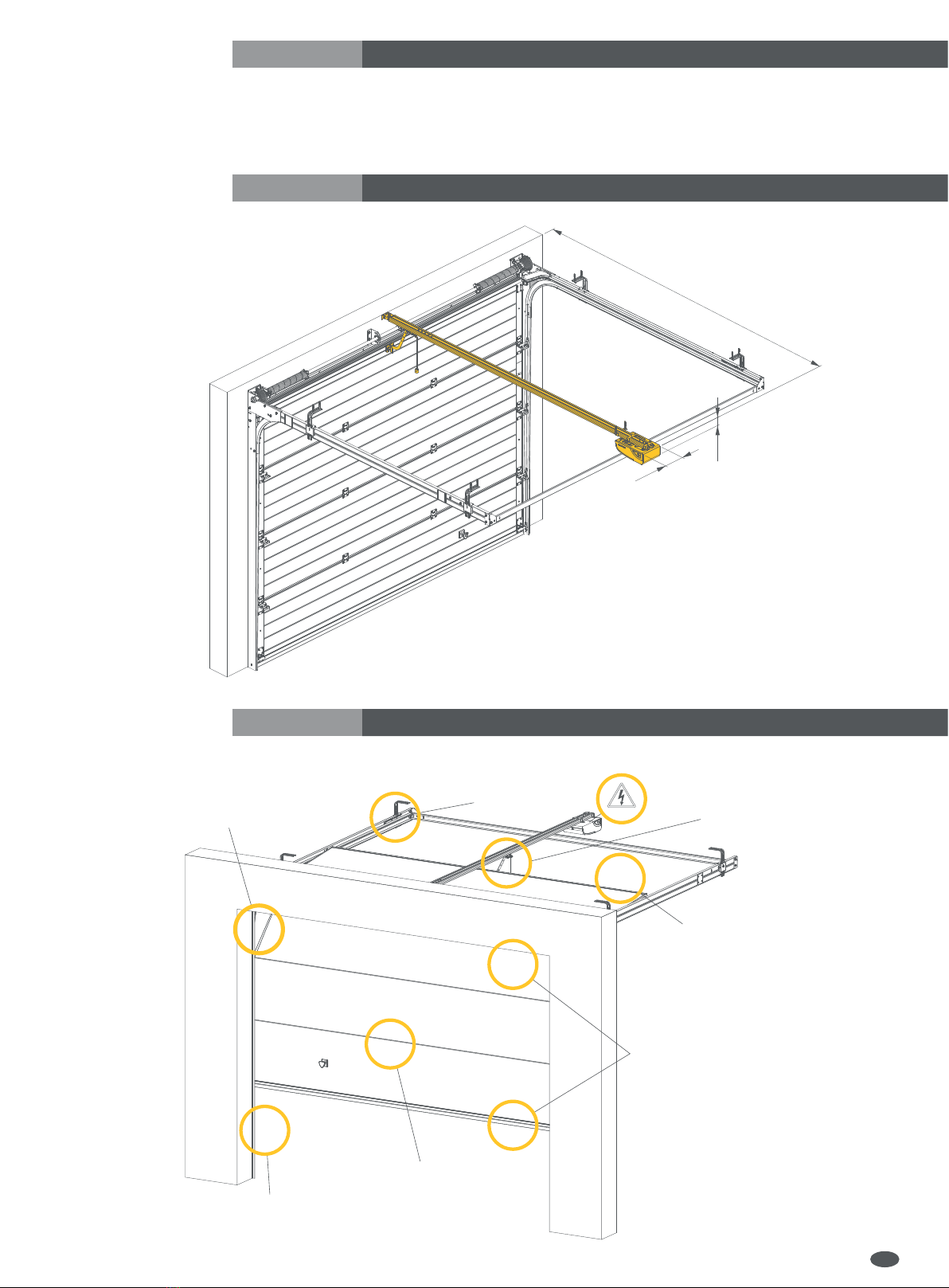
• First, install all the components, as shown in the drawings - sec. 6.4.
• Before installing the drive, make sure that the temperature range marked on the drive corresponds to local conditions.
• Connect the machine using the plug / socket set. Before connecting the drive, make sure that power supply voltage complies with the
requirements of the device to prevent the burnout of its electrical equipment due to insufficient voltage.
• Plugs must match outlets - never change the plug on other than provided by the manufacturer, do not use any additional adapters
plugs to connect the drive to the power supply.
• Before any work on the system, cut off the power supply.
In each system we recommend installing at least one warning light. Never modify the automatic drive components.
e installer should provide the user with all the information related to the manual operation of the system in case of failure and also should
provide user with the user manual.
After installation:
• Make sure that the mechanism is properly adjusted and that the door moves back or you are able to remove the obstacle when the
door touches an object with a height of 50 mm lying on the ground;
• make sure that no part of the door enters a public space, including the pavement and/or road;
• leave the work area in good order, do not leave packaging (foil, polystyrene, etc.) within reach of children as such materials may
generate a potential threat,
• pictograms warning against entrapment must be attached in a sustainable manner, near the danger area or close to the controls,
• pictogram indicating the manual release mechanism must be attached next to the mechanism.
Inform the user that the independent dismantling of the drive is unacceptable.
ese activities may be performed only by professional installers or qualified
persons designated by the manufacturer - Krispol.
4.2. Warning and safety signs
DANGER - for the user it means a risk of accidents, including fatal
NOTE - an advice on how to prevent wearing of the product
REMEMBER - key functions or useful information; pay maximum attention to the information marked with this symbol
ADDITIONAL INFORMATION
ELECTRICAL HAZARD
PROHIBITION - do not remove safety devices
COMMANDS - cut off the power supply before starting work on the device or repairs
EN

27
WARNING - risk of entrapment of a child staying close to a moving garage door.
Keep children away from the moving garage door.
5. Structure of the drive
5.1. Technical data
5.2. Construction of the drive and its components
NOTE! e product can be operated only after the installation process is fully
completed which should be ended by a full final inspection - see sec. 7.1.
Technical data of STARCUS Drive
Parameter Unit Drive
K06 K10
Type - e drive for the automation of garage doors
Power supply 230VAC (+10%) 50Hz
Electric motor
Maximum input power W 150
Power consumption A 0,7
Pulling power N 600 1000
Lighting - LED
Lighting working time s 180
Emitted sound pressure level dB(A) max 70
Permissible ambient temperature °C -20 to +50
Relative humidity % ≤ 90
Frequency of the receiver MHz 433,92
e maximum distance from the ceiling mm 1000
Normal speed without load cm/s 16
Maximum frequency of cycles % DE 40%
Maximum continuous working time s 60
Protection level IP
Technical data of the transmitter
Parameter Unit Transmitter
Type - 3-channel transmitter, remotely
Frequency MHz 433,92
Coding - Variable code system
Buttons szt. 4
Diode
Power supply V 3
Battery type - 2x CR2016
Capacity mAh 220
Permissible ambient temperature °C -20 to +50
e drive is equipped with:
• control board,
• gear motor,
• a push-button panel with display,
• LED lighting.
e set includes - p. 26
EN

28
3
1
8
11 13*
7
5
2
6
9
12
or
10
4
START / STOP
1- rail
2- drive head
3- drawbar
4- carriage handle
5- fastener for fixing the draw bar to a panel
6- fastener for fixing the drive to the rail
7- rail mounting element
8
9
10
11
12
13
*
- a fastener for fixing the rail to the lintel
- unlocking string
- transmitter
- minor elements
- rail lock
- rail suspension
- option
EN

29
5.3. Additional equipment
5.4. Installation dimensions
5.5. Hazardous areas
Additional equipment consists of:
• key switch
• Bell button connector
• photocells
• reed switch (for sectional garage doors equipped with service door).
Wn=3160/4060
200
150
1. At the side edges:
e risk of being crushed between the side
edges and adjacent fixed elements.
2. At the horizontal guides:
e risk of pinching between the
horizontal guides and rollers.
e vertical guides and rollers.
3. At the drive rail:
e risk of catching between the drive
rail and door casing.
4. At the rear edge:
e risk of being crushed in the lintel area
during closing, and in the area of adjacent
fixed elements, during opening.
5. At the main edge:
e risk of being crushed during closing
(near the ground) and during opening
(near the lintel).
6. On the surface of the curtain:
Risk of injury and pinching between
the casing panels.
7. At the vertical guides:
e risk of injury and pinching
between the vertical guides
and rollers.
EN

30
6. Installing the drive with the garage door
6.1. Tools for assembly
6.2. List of cables
6.3. Preliminary checks before installation
For mounting K06/K10 drive, you need the following tools:
* A hammer drill with appropriate drill bits for concrete and metal.
e table below shows the characteristics of the cables required to connect various devices (accessories).
Use only cables of proper insulation class.
All work on the electrical system should be performed by qualified person.
A grounded electrical socket of 230 V should be installed near the door drive. Loose wires cannot touch
the moving elements of the door and the automatic drive.
e drive must be installed by qualified personnel in compliance with current legislation, standards, regulations and according
to this manual.
• Before the installation, check that all the components and materials to be used are in perfect condition, suitable for use and in
accordance with the standards. Make sure you have chosen the correct model, and that the product is suitable for installation
in a given environment.
• Check whether the floor (structure) for mounting the garage door and the drive has been properly prepared.
• e drive should be installed at a minimum height of 2.5 m above the floor or access level.
• If the door base (construction object) is not properly prepared, do not start the installation works, as they may generate safety risks
for door users or damage the product.
• After installing the garage door, make that sure all the sliding route during closing and opening, has no areas of increased friction.
• Check the strength of the mechanical locks and check for potential danger of door jumping out of its guides.
• Check that the mechanical structure of the door is sufficiently stable and make sure there is no risk of door falling out of its guides.
• Make sure that the door moves without resistance.
• Make sure the door is well balanced - the door set (manually) in one position can not move.
• Set the door manually in the Opening and Closing position, ensuring that the entire movement has equal and uniform friction
at each point (there should be no place requiring more force).
• Make sure that the places of mounting individual elements of the drive are safe and provide protection against accidental impacts.
• Make sure that the selected surfaces for fixing the photocells are flat and suitable for a good alignment of the photocells.
• Check whether the minimum and maximum gaps are as indicated on the drawing(s).
Ø
Ø10mm
6mm
Ø
Ø8mm
Ø10mm
6mm
3mm
6mm
8
10
13
Connection Cable type
photocells cable 2/4x0,5 mm2
key switch or button switch cable 2x0,5 mm2
beacon cable 2x0,5 mm2
reed switch / STOP cable 2x0,5 mm2
3160 / 4060 mm
320 mm
~26º
EN

31
6.4. Installation
e mounting location should be kept clean and should be tidied up after installation. e future users should be trained.
e control element, which activates the support function (the function requires constant pressing of the control element by
the operator) should be located in a place where the driven part is directly seen but away from moving parts. e installation height of
the control element should be at least 1.5 m and be convenient for maintenance. e fixing point should be inaccessible to the public.
Before starting the installation of the drive, make sure that there are no entrapment areas between the door and its fixed parts
during opening.
* - option EN
1.10
1.3
1.3
1.5
1.2
1.4
1.1
1.2 1.3
ST 6,3x22
M6
M6
1.4
1.4
M6
M6
1.6
Ø4,5mm
1.5
1.5
Ø4,5mm
1.9
M6
M6x16
M6
1.8
1.8
M6
M6x16
M6
1.12
1.7
1.11
Gb 6,3x16
1.6
1.6
Gb 6,3x16
1.10
1.10*
M8x16
M8
1.16*
1.9
1.9
1.15
1.11
1.11
1.17 1.14
1.19
1.18
1.23
1.17
1.17
1.17
1.22
1.16
1.16
1.21
MAX
1.15
1.20
1.14*
~23˚
1.13
1.18
500
1.13*
1.7* 1.8*

32
Electrical wires should be arranged as shown in Fig.
1. e cable for the
signal lamp
2. e cable for
photocells
3. e cable for the
photocells and
coding keypad
5. e cable for the
socket
4. e cable for
the manual
switch
EN

33
6.5. Electrical connections
All electrical connections must be made after the power supply is cut off and with any potential emergency battery disconnected.
To connect an external control, safety and signalling device, use openings provided for this purpose (sealed with gaskets) in the control
unit housing.
Install the electrical connections according to the diagram shown in the figure below.
After installation, make sure that electrical wires do not touch the moving parts of the garage door.
Check the status of inputs and make sure that all safety devices are properly connected.
Program the drive using the control panel (see sec. 7):
IMPORTANT! Before starting any work on the control panel
(connection, maintenance), always cut off the power supply.
Wiring diagram of the control board
1 2 3 4 5
Pulse switch Photocells Lamp Reed switch / STOP Emergency battery
EN
-
+
4 FLASH
2 PB
3 PE
+24V DC
STOP
ANT
6 BAT
24V/2.4Ah
+- COM
-
+OUT
GND
FLASH
NC
5 DOOR
RXTX
NC
STOP
GND
GND
PB
NO
NC/NO
NC NO
MAX
5OOW
COM
NO
NC
L
230V AC
N PE

34
PREPARATION
1 e lever releasing the carriage is set in the horizontal position, move the door manually
2 Turn on the power, the lamp lights up when the display shows a value from '99' to '11' 99 - 11
3 The display shows the standby position '- -' ––
SETTING THE OPENING AND CLOSING POSITION
1 Press and hold the "P" button, until 'P1' is displayed P1
2 Press the "P' button again, 'OP' will be displayed OP
3 Press and hold down the "∆" button, during opening process 'OP' flashes OP
4 Release the "∆" button when the opened position is reached
5 Use "∆" and " " buttons to adjust the opening position
6 Press 'P", 'CL' will be displayed CL
7 Press and hold down the " " button, during opening process 'CL' flashes CL
8 Use "∆" and " " buttons to adjust the closing position
9 Press "P", the door will open and close automatically to establish the required normal mechanical force. '- -' will be displayed at the end ––
ADDING REMOTE CONTROLS.
1 Please press the "C" button, 'Su' will be displayed. Su
2 Select and press the button on the remote control.
3 Press the same button again to confirm. 'SU' will start flashing, and then you will see '- -'. SU
4Repeat the above steps to add additional eKey remote controls. e memory may store the maximum of 20 remote controls.
An attempt to add another remote control will result in displaying 'FU'
DELETING REMOTE CONTROLS
1 Note: is feature will delete all remote controls
2 Press and hold the "C" button for 8 seconds. 'dL' will be displayed. dL
ADJUSTING THE MECHANICAL FORCE
1 Press and hold the "P" button, until 'P1' is displayed P1
2 Press the "∆" button once. 'P2' will be displayed P2
3Press "P" again. e current force settings will be displayed. Simultaneously, press "∆" or " " to increase or decrease the force value by one step.
e maximum value is 'F9', while the minimum is 'F1'. Press P to confirm.
4 e default settings is 'F3' F3
PHOTOCELL ACTIVATION AND DEACTIVATION
1 Press and hold the P button until 'P1' is displayed P1
2 Press the "∆" button twice. 'P3' will be displayed P3
3 Press the "P" button to see to the status of the photocell. 'H0' means that it is OFF, 'H1' means that is ON H0 - H1
4 Press the "∆" button to activate. 'H1' will be displayed. H1
5 Press the " " button to inactivate. 'H0' will be displayed. H0
6 Press P button to confirm and exit.
7Note: If the photocells are not installed, make sure that the above-mentioned function is disabled.
Otherwise, the operating mechanism will open, but it will not close.
AUTOMATIC CLOSING
1 Press and hold the P button until 'P1' is displayed P1
2 Press the "∆" button three times. 'P4' will be displayed P4
3 Press the "P" button to display the status of the automatic closing. 'b0' means no automatic shutdown, while 'b9' means the maximum closing. b0 - b9
4 Press the "∆" button to increase or " " to decrease the delay by one minute.
5 Press P button to confirm and exit.
LOCKING THE REMOTE CONTROL
1 Press and hold the P button until 'P1' is displayed P1
2 Press the "∆" button four times. 'P5' will be displayed P5
3 Press "P" again. e current setting will be displayed: 'uL' - no lock of the remote control. uL
4 Press the "∆" button once. 'Lc' will be displayed - indicating the activation of the lock of the remote control. Lc
5 Press P button to confirm and exit.
VENTILATION - AIRING
1 Press and hold the P button until ‘P1’ is displayed.
2 Press the ∆button five times. ‘P6’ will be displayed.
3Press the P button again. e current setting 'r0' will be displayed - ventilation not active. Press the ∆and s buttons simultaneously
to increase or to decrease this value by one level. e maximum value is 'r9'; the minimum value is 'r0'. Press P to confirm. r0 - r9
4 Enable the ventilation option by pressing the CH1 and CH2 buttons simultaneously
OUTDOOR LIGHTING TIME SETTINGS
1 Press and hold the P button until 'P1' is displayed P1
2 Press the ∆button six times. 'P7' will be displayed P7
3Press P again. e current setting 'L0' will be displayed - external lighting timeswitch is not active.
e maximum value is 'L4'; the value changes by 30 seconds L0 - L4
4 Press P to confirm.
Opening the garage door
uL – opening of the door by pressing a pre-programmed button in the appropriate channel.
Lc – opening of the door by pressing a button with the padlock symbol and then a pre-programmed button in the appropriate channel.
Closing the garage door
uL/Lc – pressing a pre-programmed button in the appropriate channel.
Cautions and Warnings
Operate the garage door only when you see everything within its moving range. Do not allow children to play with control mechanisms. Make sure that people are not within the range
of moving garage door. e same applies to animals or objects. e drive is designed for indoor installation and operation. e garage door and the control mechanism should be serviced
every year. Restoring the factory settings of the mechanical force involves steps described in sec. 24-26
7. Programming
EN
1x
6x
2x PIN +
← CH1 / 2x PIN +
← CH2
CH1
CH3
CH2
1x
2x 6x

35
7.1. Final inspection and start-up
is is the most important stage of the drive installation process and is intended to ensure maximum safety.
After determining the position of opening and closing, it is recommended to perform several manoeuvres to check the correct movement
of the garage door:
• Press the button on the remote control to open the door; Check whether door opening is smooth with no jerks or speed changes.
e garage door should open completely. e drive should stop when the door is in the fully opened position.
• Press the button on the remote control to close the door; Check whether door closing is smooth with no jerks or speed changes.
e garage door should close completely. e drive should stop when the door touches the ground.
• If the drive is installed with a beacon lamp (optional) to check if the lamp flashes in cycles of ... seconds ON and ... seconds OFF.
• If the drive is to be installed along with photocells check whether the system works correctly.
• If the drive is installed with the garage door equipped with a service door, check the reed switch for correct operation.
e user should not be able to open the garage door when the service door is not closed properly. Perform the test run.
• Set an obstacle in the closing area and start the closing operation. Check whether the amperometric protection works properly.
e door wing after colliding with the obstacle should stop and change its movement direction (in opening direction).
• Perform several opening and closing manoeuvres to detect any defects in the assembly or improper adjustment,
e.g. moments of increased friction.
• Check whether the fixing of the drive, guide and all mechanical components is strong, stable and durable.
• Verify that the system can detect an obstacle with a height of 50 mm, lying on the ground.
Attach a label informing about the possibility and method of using the manual release mechanism of the door near the mechanism.
Attach a warning sticker (Fig. ... sec. 4.2 and below) in a visible place near the garage door or in the vicinity of the control system.
After completing:
• a full check of correct installation and operation of the garage door with the drive,
• electrical measurements,
legibly fill out all the necessary forms in the Report Book, which is an integral part of the garage door manual.
Provide the user with the manual, introduce the principle of the system and show how to release and lock again the manual release
mechanism.
Sign the declaration of conformity and provide it to the user.
EN

36
8. Commissioning
9. Replacing components
Commissioning may take place only after a positive result of all the stages of the acceptance, according to
the provisions of sec. 7.1.
A partial or ‚temporary’ commissioning is prohibited.
Check whether all the warning pictograms are attached and verify that the drive and the garage door have a nameplate.
e end user should be trained in using controls, maintain mechanisms of the door
and in their adjustment, technical aids, rules of maintenance, repair and compliance with health and safety during the operation of the door
and drive in accordance with the requirements of manual and the Report Book.
Commissioning primarily involves: training of users, demonstrating the operation and providing the manual of the door with the drive along
with the regular maintenance manual, Report Book and EC/EU declaration of conformity signed by the installer for the drive with the door.
Replacing components may be carried out after cutting off the power supply by removing the plug from the socket.
e works presented below should be performed by qualified servicing team, preferably the same, which conducted the installation
of the drive.
Before replacing the fuse, cut off the power supply by pulling the plug out of the socket.
Replace the fuse with a new one. e drive uses a miniature fuse of 2.5 A F.
9.1. Replacing the fuse
9.2. Replacing the batteries in the remote control
1. 2.
2,5A L 250V
CR2032
3V
EN

37
Replacing the entire drive requires removing the drive and disconnecting the wires from the control board. Activities should be carried out
in reverse order to the installation operations.
After mounting the drive, all the checks described in sec. „Final inspection and start-up” should be carried out.
Add what else may be replaced by the installer.
In order to find a cause of any potential defect, use the short instruction manual and test the door manually.
Check the operating mechanism for proper operation when the door is disconnected.
As in the case of installation, the dismantling steps must be performed by qualified technical personnel.
During the disposal, follow the safety regulations concerning the dismantling of electrical equipment, recycling electronics and procedures
for preventing environmental contamination.
All parts of the device must be segregated and subject to proper disposal.
• e Guarantee Card is an integral part of the manual.
• Remember to fill the Guarantee Card during the commissioning of the drive with the garage door.
• e Report Book is an integral part of the manual.
• Remember to fill the Report Book during the commissioning of the drive with the garage door.
9.3. Replacing the drive
10. Troubleshooting
11. Dismantling and disposal
12. Guarantee Card
13. Report Book
Problem Possible cause Remedy
1. Loud chain. 1. e chain is loose. 1. Tighten M8 nut on the spring.
2. e motor does not respond. 2. Power supply failure, loose plug,
triggered fuse.
2. Check the electrical network. Check or replace
the fuse with a fuse of the same type.
3. e door opens but does not close. 3. Faulty photocell (if fitted). 3. Perform the test after removing the photocell
(please refer to the programming section).
4. e motor operates after pressing the
activation button, but it does not work
when activated by the remote control.
4. Defect of the remote control or
discharged battery.
4. Replace the battery in the remote control. If two
or more remote controls do not work, replace the
control board.
5. Remote control range is short. 5. Discharged battery of the
remote control. 5. Replace the battery in the remote control.
6. e door does not close completely and
opens again, or does not open completely.
6. e operating mechanical force
is too low.
6. Perform a manual test of the garage door.
Gently increase the operating mechanical force of
the door (please refer to the programming section).
Any work on electrical equipment unit may be performed only by a person with
appropriate and valid license.
NOTE: e electrical waste must be disposed to authorized collection points.
EN

102 SE

103
Innehållsförteckning
Försäkran om inbyggnad 2
1. Inledning 104
2. Produktens identifieringsuppgifter och avsedda användning 104
3. Allmänna montageuppgifter 105
4. Installationssäkerhet och varningar 105
4.1. Allmänna regler 105
4.2. Varningar och säkerhetsmärkning 106
5. Uppbyggnad av drivanordningen 107
5.1. Tekniska data 107
5.2. Uppbyggnad och komponenter 107
5.3. Extra utrustning 109
5.4. Monteringsmått 109
5.5. Farliga zoner 109
6. Montage av eldriven port 110
6.1. Montageverktyg 110
6.2. Förteckning över ledningar 110
6.3. Preliminär kontroll före montage 110
6.4. Montage 111
6.5. Anslutning till elnätet - kopplingar 113
7. Programmering 114
7.1. Slutkontroll och uppstart 115
8. Idriftsättning 116
9. Utbyte av delsystem 116
9.1. Utbyte av säkring 116
9.2. Utbyte av ärrkontrollens batteri 116
9.3. Utbyte av drivanordning 117
10. Felsökning 117
11. Avmontering och skrotning 117
12. Garantikort 117
13. Rapportbok 117
SE

104
1. Inledning
2. Produktens identifieringsuppgifter och avsedda användning
Denna bruksanvisning är endast avsedd för kvalificerade installatörer.
Personen som installerar en eldriven port är ansvarig för korrekt montage och justering samt portens felfria funktion.
Efter montaget får ägaren till eldriven port följande dokument:
• bruksanvisning
• anvisningar för löpande underhåll
• rapportbok
• deklaration om överensstämmelse undertecknad av en behörig installatör (efter att framgångsrikt ha funktionstestat den eldrivna
porten,drivanordningen, styrning och alla skyddelement).
En eldriven port får ej användas förrän den satts i drift, enligt beskrivning i kapitel 8: „Idriftsättning”.
Om du har funderingar avstå från att installera produkten och kontakta tillverkaren
– företaget Krispol eller ett behörigt serviceställe – för eventuella förklaringar.
Produktens identifieringsuppgifter är angivna på märkskylten placerad på drivhuvudet. Drivanordningen erbjuds i två versioner:
STARCUS K06 och STARCUS K10.
En användarvänlig och modernt utformad drivanordning avsedd för automatiska takskjutportar.
Drivanordningen är tillgänglig i två versioner med olika effektparametrar som motsvarar portar med maximal yta på respektive
8 eller 14 kvm.
Produkten är utrustad med:
• amperometrisk hinderdetektering - när den stöter på ett hinder stannar den och ändrar sin rörelseriktning,
• mjukstart- och mjukstoppfunktion för att undvika starka ryckningar när porten börjar öppna/stänga,
• integrerad LED-lampa som belyser den öppnande garageporten (tre minuters belysningstid),
• överbelastningsskydd,
• möjlighet att programmera den automatiska stängningen,
• LED-display för enkel programmering av funktioner.
Dessutom kan följande anslutas:
• mikrobrytare för servicedörrar som blockerar porten när servicedörren är öppen,
• fotoceller samt nödavstängning av drivanordningen från utsidan i händelse av strömavbrott.
En grunduppsättning innehåller:
• driftanordning med inbyggd radiomottagare 433,92 MHz,
• sändare (3-kanaler),
• skena med band eller kedja (att välja mellan),
• monteringselement.
Uppsättningens beståndsdelar beskrivs närmare i kap. 5.2 (se s. 105).
Drivanordningen bör installeras minst 2,5 m övanför golvet eller tillträdesnivån.
Drivanordningen får inte användas med portar som har öppningar på en diameter större än 50 mm eller kanter/utskjutande delar som
går att stå på eller gripa efter.
Drivanordningen lämpar sig för garageportar med följande parametrar:
Wn - inbyggnadsdjup i porten
A - 600N, 3100mm
B - 600N, 4000mm
C - 1000N, 3100mm
D - 1000N, 4000mm
SE
DRIVNING N, L, SL, NH, E
DRIVNING H
Wn höjd/bredd 2200 2300 2400 2500 2600 2750 3000 3250 3500 3750 4000 4250 4500 4750 5000 5250 5500 5750 6000
3160 2000
2125
4060
2250
2375
2500
2625
2750
C
A
BD
Wn höjd/bredd 2200 2300 2400 2500 2600 2750 3000 3250 3500 3750 4000 4250 4500 4750 5000 5250 5500 5750 6000
3160
2000
2125
2250
4060
2375
2500
2625
2750
2875
3000
A C
BD

105
Anslutning av ytterligare element, programmering av ärrkontroller samt montering av drivanordningen beskrivs vidare i monteringsanvisningen.
I händelse av strömavbrott kan den elektriska drivanordningen låsas upp och öppna/stänga porten manuellt.
Man kan också förse drivanordningen med ett nödbatteri för att kunna använda den oavsett strömförsörjning.
Drivanordning tillsammans med takskjutport är avsedd för fordonstrafik och fotgängare.
Den ska installeras i bostadsfastigheter och är endast avsedd för enskilda hushåll. Drivanordningen bör inte installeras på portar avsedda för
montering i offentliga byggnader. De får inte installeras i industriella och kommersiella fastigheter. Drivanordningen är avsedd att användas
inomhus.
Den får inte installeras utomhus eller i utrymmen som är explosionsfarliga eller där det befinner sig lättantändliga vätskor, gaser eller damm.
Det är förbjudet att utsätta drivanordningen för regn eller fukt.
Drivanordningen tillsammans med takskjutporten kan installeras på en stödkonstruktion i ett bostadshus.
Krav beträffande monteringsunderlag för eldriven port:
• murverk: tork och jämn yta med lämplig hållfasthet, utförd i enlighet med gällande byggregler,
• metallkonstruktion: korrekt struktur och lämplig styrka.
Beroende på underlag används följande monteringselement:
• expanderbultar – för armerad betong eller massivt tegel,
• självborrande skruvar – för stålkonstruktioner,
• bultar för håltegel och porbetong – för underlag av håltegel, porbetong eller annat material med liknande egenskaper.
Den exakta typen och storleken på fästelementen bestäms individuellt med kunden. Det är köparens ansvar att garantera lämpliga
fästelement.
Stödkonstruktionen bör möjliggöra rätt borrning av monteringshål.
Stället där porten ska installeras bör vara rätt belyst och
garantera säker användning av porten. Portens ägare bär ansvar för att de ovanstående kraven uppfylls.
• Monteringselement levereras tillsammans med drivanordningen.
• Använd aldrig andra monteringselement än de som finns bifogade till produkten.
• Alla elektriska anslutningar kan endast utföras när strömförsörjningen och eventuellt nödbatteri är bortkopplade.
Följ den installationsprocedur som beskrivs i denna handbok för att garantera felfri och säker funktion av den eldrivna porten.
Fel montage eller fel användning kan leda till allvarliga kroppsskador och materiella skador.
Läs anvisningarna innan du påbörjar montaget. Genomför aldrig ändringar som inte beskrivs i detta dokument.
Det är förbjudet att installera drivanordningen för andra ändamål än de som anges i denna bruksanvisning.
För fästning kan man endast använda bifogade verktyg och beståndsdelar, och i varje fall sådana fästelement (skruvar,
expanderbultar, muttrar) som är lämpliga för fästningstyp och de belastningar som uppstår i samband med portens drift.
Innan du påbörjar installationen läs denna handbok och följ de nedanstående reglerna angående att eliminera risker och vidta lämpliga
försiktighetsåtgärder.
Under installationsarbeten använd personlig skyddsutrustning och vidta tekniska åtgärder som garanterar säkerhet för dig, andra personer,
egendom och miljö.
VARNING: Automatisk drift.
OBSERVERA! Alla avvikelser beträffande fästelement är oacceptabla och kan
vara farliga för framtida användare av porten.
VARNING: Viktiga säkerhetsanvisningar. Följ samtliga anvisningar eftersom
felaktig installation kan leda till allvarliga kroppsskador.
3. Allmänna montageuppgifter
4. Installationssäkerhet och varningar
4.1. Allmänna regler
SE
Other manuals for STARCUS K06
2
This manual suits for next models
1
Table of contents
Languages:
Other krispol DC Drive manuals