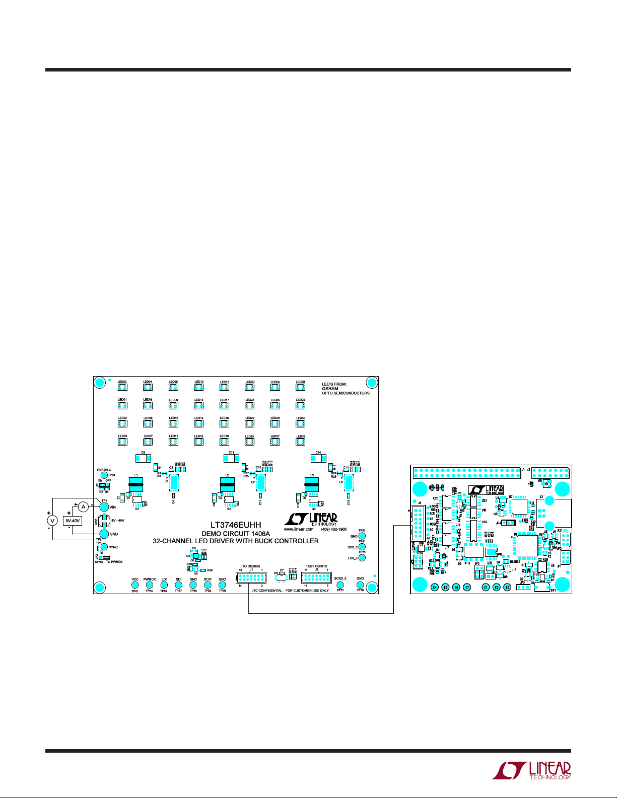
Linear LT3746 User manual

1
dc1406afa
DEMO MANUAL DC1406A
Description
LT3746
32-Channel LED Driver
Demonstration circuit 1406A features the LT
®
3746,
32-channel 20mA LED driver with buck controller and se-
rial interface. Each channel has an individually adjustable
12-bit (4096-step) grayscale PWM dimming control and
a 6-bit (64-step) dot correction current adjustment. Both
dimming control and current adjustment are accessible
via a 30MHz cascadable serial data interface. Individual
open/short LED and overtemperature flags are sent back
during status read-back.
Three LT3746’s are connected in series to control 32 RGB
LEDs stuffed on the demo board. Each IC drives a separate
color. The evaluation software installed in a host computer
perForMAnce sUMMArY
communicates with the DC1406A via the interface board
DC590B, an USB serial controller.
The LT3746 data sheet gives a complete description of
the part, its operation and application information. The
datasheet must be read in conjunction with this quick start
guide for working on or modifying the demo circuit 1406A.
Design files for this circuit board are available at
http://www.linear.com/demo
L, LT, LTC, LTM, Linear Technology and the Linear logo are registered trademarks and
QuikEval is a trademark of Linear Technology Corporation. All other trademarks are the property
of their respective owners.
SYMBOL PARAMETER CONDITIONS MIN TYP MAX UNITS
VIN Input Supply Range 9 40 V
VOUT-R Pre-Charge Voltage (Red) 3.0 V
VOUT-G Pre-Charge Voltage (Green) 4.2 V
VOUT-B Pre-Charge Voltage (Blue) 4.2 V
fSFree-Running Switching Frequency 400 kHz
Specifications are at TA= 25°C.

2
dc1406afa
DEMO MANUAL DC1406A
qUick stArt proceDUre
Demonstration circuit 1406A is easy to set up to evalu-
ate the performance of the LT3746. Refer to Figure 1 for
proper measurement equipment setup and follow the
procedure below:
1. Install the QuikEval™ System software on the host
computer. The software can be downloaded from http://
www.linear.com/designtools/software/quick_eval.jsp.
2. Install Microsoft .NET framework. The software can be
downloaded from http://www.microsoft.com/NET/
3. Copy LEDRelease folder to the host computer. Run
vcredist_x86.exe.You may need to restart the computer.
4. Place jumpers in the following positions:
JP1 On
JP2 TO PWMCK
5. Connect the demo board to DC590B as shown in
Figure 1.
6. With power off, connect the input power supply to VIN
and GND.
7. Apply 9V to 40V to DC1406A input.
8. Run LTcolorLEDarray.exe in the LEDRelease folder.
9. The initial start-up screen appears, at this point, none
of the LEDs should light up. Proceed with board evalu-
ation.
Figure 1. Proper Measurement Equipment Setup

3
dc1406afa
DEMO MANUAL DC1406A
operAting the control screen
Figure 2 is the initial start-up screen that appears when
the program is launched.
1. Send Data Frame to Chip
Double-click one oftheblack squares inthe “LED Colors”
grid. The standard color selector dialog box appears.
Select a color and click “OK.” Or select the LED number
in the “LED Configuration” grid, adjust the LED color
by moving the sliding bars.
Click the command button labeled “Send Data Frame
to Chip.” Verify that the LEDs light up in corresponding
colors.
2. Play Pattern File
Click the “Browse” button and pick the file “test”. Click
the command button labeled “Play Pattern File.” Verify
that all 32 RGB LEDs light up in red, green, blue and
white in sequence.
Check the “Auto-Update Data/Loop File” option. Click
the command button labeled “Play Pattern File.” Click
the “stop” button at any time to stop.
3. Append Data Frame to Pattern File
Create a blank text file. Click the “Browse” button and
pick this new file. Create and then add the first data
frame to the file by clicking the “Append Data Frame
to Pattern File” button. Create the second data frame
and add it to the file by clicking the “Append” button.
Repeat until all the data frames are added to the file.
Click the command button labeled “Play Pattern File.”
Figure 2. GUI Control Panel Start-Up Screen

4
dc1406afa
DEMO MANUAL DC1406A
pArts list
ITEM QUANTITY REFERENCE-DESCRIPTION DESCRIPTION MANUFACTURER’S PART NUMBER
Required Circuit Components
1 3 C1, C9, C12 Capacitor, 1206 2.2µF 10% 50V X5R Murata GRM31CR71H225KA88L
2 3 C2, C10, C13 Capacitor, 0603 0.47µF 10% 16V X7R TDK C1608X7R1C474KT
3 3 C3, C15, C16 Capacitor, 0603 10nF 10% 50V X7R AVX 06035C103KAT2A
4 3 C4, C17, C18 Capacitor, 0603 10µF 10% 6.3V X5R Murata GRM188R60J106ME47D
5 1 C5 Capacitor, 0805 1µF 10% 50V X7R Murata GRM21BR71H105KA12L
6 1 C6 Capacitor, 0603 1µF 10% 16V X7R TDK C1608X7R1C105K
7 2 C7, C19 Capacitor, 0603 0.1µF 10% 50V X7R TDK C1608X7R1H104K
8 3 C8, C11, C14 Capacitor, 7343 220µF 20% 6.3V POSCAP SANYO POSCAP 6TPE220ML
9 3 D1, D2, D3 Diode, Rectifier, Barrier, Schottky 1.0A Diodes Inc. DFLS160
10 32 LED00-LED31 LED, Top, 6-Lead OSRAM LRTB-G6TG
11 3 L1, L2, L3 Inductor, 15µH Würth 744778115
12 3 Q1, Q2, Q3 XSTR, P-channel MOSFET Vishay Si9407BDY
13 3 R1, R17, R18 Resistor, 1206 0.03Ω 1% 1/8W IRC LR1206LF-01-R030-F
14 1 R2 Resistor, 0603 499kΩ 1% 1/10W Vishay CRCW0603499KFKEA
15 1 R3 Resistor, 0603 100kΩ 1% 1/10W NIC NRC06F1003TRF
16 3 R4, R19, R20 Resistor, 0603 133kΩ 1% 1/10W Vishay CRCW0603133KFKEA
17 4 R5, R7, R21, R23 Resistor, 0603 10.0kΩ 1% 1/10W Vishay CRCW060310K0FKED
18 1 R6 Resistor, 0603 15.0kΩ 1% 1/10W YAGEO RC0603FR-0715KL
19 3 R8, R25, R26 Resistor, 0603 60.4kΩ 1% 1/10W Vishay CRCW060360K4FKEA
10 3 R9, R27, R28 Resistor, 0603 51.1kΩ 1% 1/10W NIC NRC06F5112TRF
21 1 R10 Resistor, 0603 20.5kΩ 1% 1/10W Vishay CRCW060320K5FKED
22 1 R13 Resistor, 0603 12.4kΩ 1% 1/10W Vishay CRCW060312K4FKED
23 3 R14, R15, R16 Resistor, 0603 5.1kΩ 1% 1/10W Vishay CRCW06035K10FKED
24 2 R22, R24 Resistor, 0603 24.9kΩ 1% 1/10W NIC NRC06F2492TRF
25 1 R29 Resistor, 0603 20kΩ 1% 1/10W Vishay CRCW060320K0FKEA
26 3 R31, R32, R33 Resistor, 0603 5.11Ω 1% 1/10W AAC CR16-R11FM
27 3 U1, U2, U3 IC, LT3746EUHH Linear Technology LT3746EUHH
28 1 U4 IC, LT3010EMS8E Linear Technology LT3010EMS8E
29 1 U5 IC, LTC1799CS5 Linear Technology LTC1799CS5
30 1 U6 IC, 24LC025-I/ST Microchip Tech. 24LC025-I/ST
Additional Demo Board Circuit Components
1 1 CIN1 Capacitor, 22µF 20% 50V Sanyo 50CE22BS
2 0 R30 Resistor, 0603 0Ω Jumper Option Vishay CRCW06030000Z0ED Option
Hardware
1 2 TP1, TP2 Turrets Mill-Max 2501-2-00-80-00-00-07-0
2 14 TP3, TP41, TP54-TP59, TP75,
TP77, TP79, TP81, TP83, TP84
Turrets Mill-Max 2308-2-00-80-00-00-07-0
3 2 JP1, JP2 Header, 3-Pin, 2mm Samtec TMM-103-02-L-S
4 1 J1 Header, 2×7 2mm MOLEX 87831-1420
5 0 J2 Header, 2×7 2mm Option MOLEX 87831-1420 Option
6 2 JP1, JP2 Shunt, 2mm Samtec 2SN-BK-G
7 4 Standoff, Snap-On Keystone_8831

5
dc1406afa
DEMO MANUAL DC1406A
scheMAtic DiAgrAMs

6
dc1406afa
DEMO MANUAL DC1406A
scheMAtic DiAgrAMs

7
dc1406afa
DEMO MANUAL DC1406A
Information furnished by Linear Technology Corporation is believed to be accurate and reliable.
However, noresponsibility is assumed for its use. Linear Technology Corporation makes no representation
that the interconnection of its circuits as described herein will not infringe on existing patent rights.
scheMAtic DiAgrAMs

8
dc1406afa
DEMO MANUAL DC1406A
LinearTechnology Corporation
1630 McCarthy Blvd., Milpitas, CA 95035-7417
(408) 432-1900 ●FAX: (408) 434-0507 ●www.linear.com
LINEAR TECHNOLOGY CORPORATION 2011
LT 0411 REV A • PRINTED IN USA
DEMONSTRATION BOARD IMPORTANT NOTICE
Linear Technology Corporation (LTC) provides the enclosed product(s) under the following AS IS conditions:
This demonstration board (DEMO BOARD) kit being sold or provided by Linear Technology is intended for use for ENGINEERING DEVELOPMENT
OR EVALUATION PURPOSES ONLY and is not provided by LTC for commercial use. As such, the DEMO BOARD herein may not be complete
in terms of required design-, marketing-, and/or manufacturing-related protective considerations, including but not limited to product safety
measures typically found in finished commercial goods. As a prototype, this product does not fall within the scope of the European Union
directive on electromagnetic compatibility and therefore may or may not meet the technical requirements of the directive, or other regulations.
If this evaluation kit does not meet the specifications recited in the DEMO BOARD manual the kit may be returned within 30 days from the date
of delivery for a full refund. THE FOREGOING WARRANTY IS THE EXCLUSIVE WARRANTY MADE BY THE SELLER TO BUYER AND IS IN LIEU
OF ALL OTHER WARRANTIES, EXPRESSED, IMPLIED, OR STATUTORY, INCLUDING ANY WARRANTY OF MERCHANTABILITY OR FITNESS
FOR ANY PARTICULAR PURPOSE. EXCEPT TO THE EXTENT OF THIS INDEMNITY, NEITHER PARTY SHALL BE LIABLE TO THE OTHER FOR
ANY INDIRECT, SPECIAL, INCIDENTAL, OR CONSEQUENTIAL DAMAGES.
The user assumes all responsibility and liability for proper and safe handling of the goods. Further, the user releases LTC from all claims
arising from the handling or use of the goods. Due to the open construction of the product, it is the user’s responsibility to take any and all
appropriate precautions with regard to electrostatic discharge. Also be aware that the products herein may not be regulatory compliant or
agency certified (FCC, UL, CE, etc.).
No License is granted under any patent right or other intellectual property whatsoever. LTC assumes no liability for applications assistance,
customer product design, software performance, or infringement of patents or any other intellectual property rights of any kind.
LTC currently services a variety of customers for products around the world, and therefore this transaction is not exclusive.
Please read the DEMO BOARD manual prior to handling the product. Persons handling this product must have electronics training and
observe good laboratory practice standards. Common sense is encouraged.
This notice contains important safety information about temperatures and voltages. For further safety concerns, please contact a LTC applica-
tion engineer.
Mailing Address:
Linear Technology
1630 McCarthy Blvd.
Milpitas, CA 95035
Copyright © 2004, Linear Technology Corporation
Table of contents