2
SANITARY STANDARDS
4
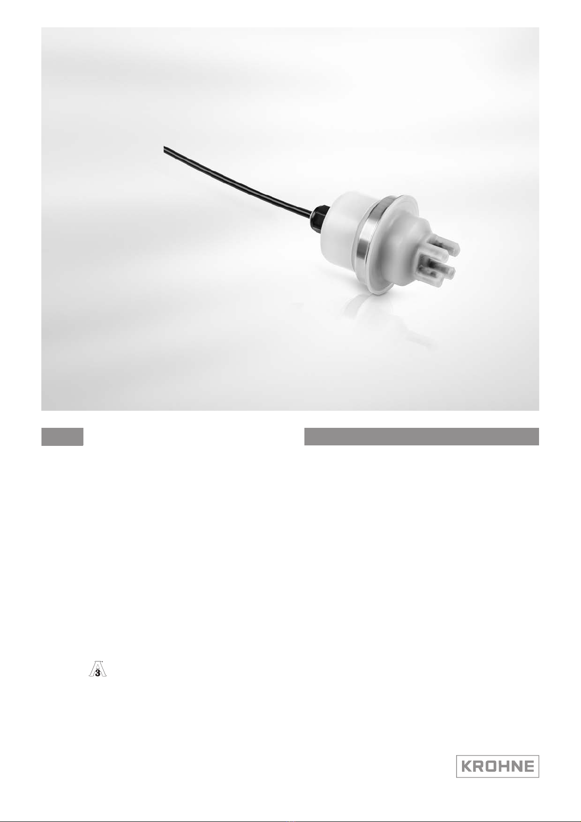
OPTISENS TSS 7000
www.krohne.com 06/2020 - 4007124802 - AD OPTISENS TSS 7000 3-A R02
2.1 3-A Standards - Meaning and implementation
Meaning of 3-A
The 3-A Sanitary Standards Incorporation publishes hygiene standards which contain guidelines
for materials, design and manufacturing methods. The organisation verifies compliance to the
hygienic design. Compliance is inspected by an independent third body, the CCE (Certified
Conformance Evaluator). Once compliance has been verified, the 3-A SSI (Sanitary Standards
Incorporation) issues a symbol licence for the 3-A logo.
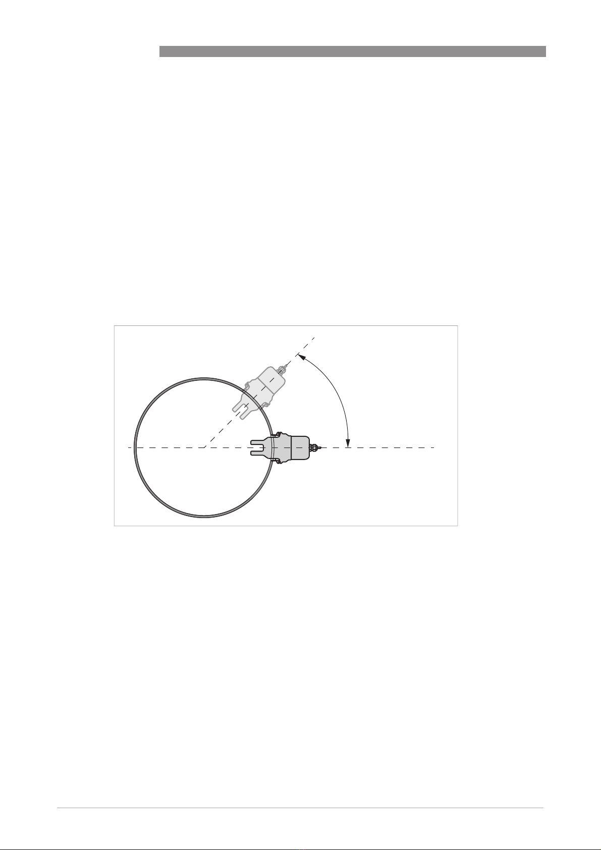
Use of devices in accordance with 3-A
The use of devices and components that bear the 3-A logo is evidence that the design has been
inspected. The certificate always applies to a combination of a sensor and process connection.
Both components in this combination must conform to 3-A standards. It looks like this:
Use in accordance with 3-A entails enhanced or special requirements compared to standard
applications. This applies in particular to:
•Housing design (e.g. easy to clean)
•Process connection design (e.g. visibility of potential leaks)
•Gaskets (e.g. FDA or 3-A compliance, stability)
•Installation position on the tank (e.g. self-draining)
•Cleaning, maintenance (intervals, methods)
46
04