KROHNE SENSOFIT RET 5000 User manual

Manual retractable assembly
SENSOFIT RET 5000
SENSOFIT RET 5000SENSOFIT RET 5000
SENSOFIT RET 5000 Handbook
HandbookHandbook
Handbook
© KROHNE 03/2018 - 4003819102 - MA SENSOFIT RET 5000 R02 en

All rights reserved. It is prohibited to reproduce this documentation, or any part thereof, without
the prior written authorisation of KROHNE Messtechnik GmbH.
Subject to change without notice.
2
S
www.krohne.com 03/2018 - 4003819102 - MA SENSOFIT RET 5000 R02 en
Copyright 2018 by
KROHNE Messtechnik GmbH - Ludwig-Krohne-Str. 5 - 47058 Duisburg (Germany)
:
IMPRINT
:::::::::::::::::::::::::::::::::::::::

CONTENTS
3
www.krohne.com03/2018 - 4003819102 - MA SENSOFIT RET 5000 R02 en
SENSOFIT RET 5000
1 Safety instructions 5
1.1 Intended use ..................................................................................................................... 5
1.2 Certifications .................................................................................................................... 5
1.3 Safety instructions from the manufacturer ..................................................................... 6
1.3.1 Copyright and data protection ................................................................................................ 6
1.3.2 Disclaimer ............................................................................................................................... 6
1.3.3 Product liability and warranty ................................................................................................ 7
1.3.4 Information concerning the documentation........................................................................... 7
1.3.5 Warnings and symbols used................................................................................................... 8
1.4 Safety instructions for the operator................................................................................. 8
2 Device description 9
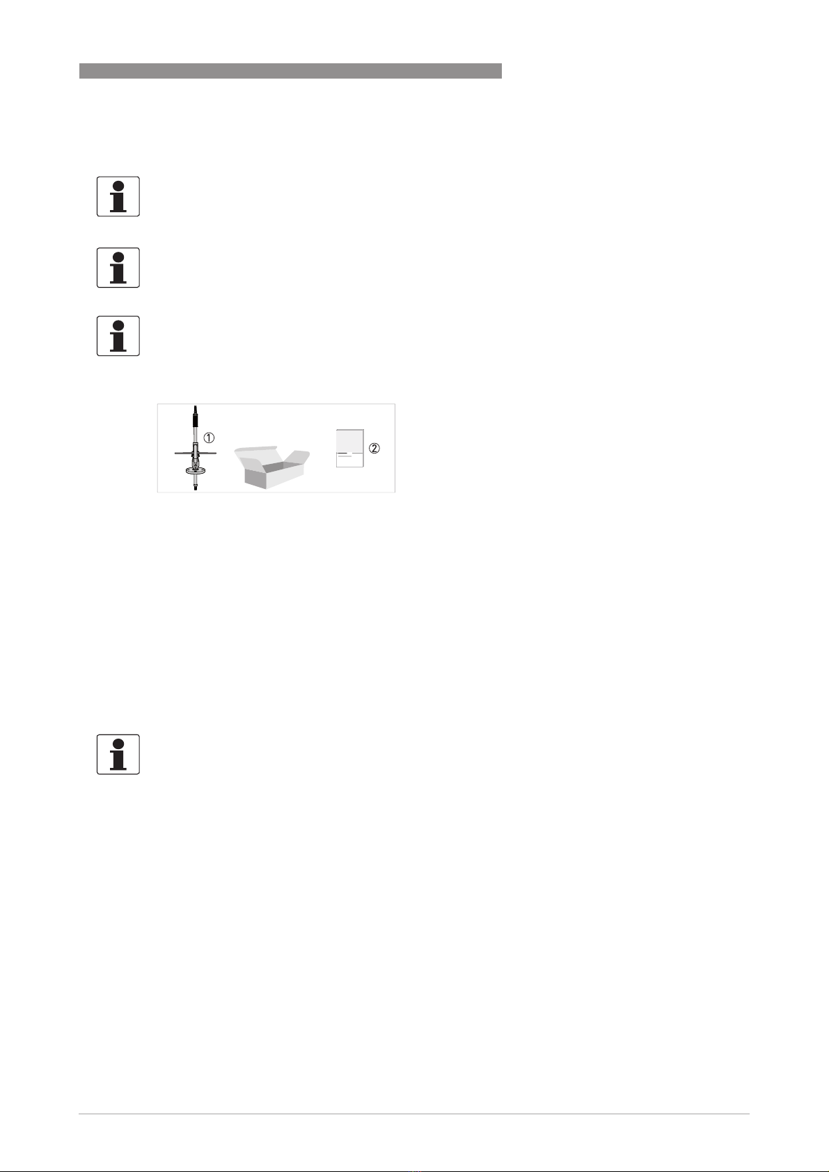
2.1 Scope of delivery............................................................................................................... 9
2.2 Device description .......................................................................................................... 10
2.3 Nameplate ...................................................................................................................... 10
3 Installation 11
3.1 General notes on installation ......................................................................................... 11
3.2 Storage and transport .................................................................................................... 12
3.3 Pre-installation requirements ....................................................................................... 12
3.4 Install the assembly .......................................................................................................13
3.4.1 Install the sensor .................................................................................................................. 14
3.4.2 Adjust the immersion depth ................................................................................................. 16
3.4.3 Install the sliding device ....................................................................................................... 17
3.4.4 Install the flush tube............................................................................................................. 18
4 Operation 21
4.1 Put the assembly into operation .................................................................................... 21
4.2 Moving the assembly manually...................................................................................... 22
4.3 Removing the sensor...................................................................................................... 23
4.4 Troubleshooting.............................................................................................................. 25
5 Service 26
5.1 Maintenance ................................................................................................................... 26
5.1.1 Replace the O-rings .............................................................................................................. 26
5.1.2 Checking for functionality and leakage ................................................................................ 29
5.1.3 Service instruction ................................................................................................................ 29
5.2 Availability of services .................................................................................................... 30
5.3 Spare parts availability...................................................................................................30
5.4 Returning the device to the manufacturer..................................................................... 30
5.4.1 General information.............................................................................................................. 30
5.4.2 Form (for copying) to accompany a returned device............................................................ 31
5.5 Disposal .......................................................................................................................... 31

CONTENTS
4
www.krohne.com 03/2018 - 4003819102 - MA SENSOFIT RET 5000 R02 en
SENSOFIT RET 5000
6 Technical data 32
6.1 Technical data................................................................................................................. 32
6.2 Temperature - pressure diagram.................................................................................. 33
6.3 Dimensions ..................................................................................................................... 34
7 Notes 37

SAFETY INSTRUCTIONS
1
5
SENSOFIT RET 5000
www.krohne.com03/2018 - 4003819102 - MA SENSOFIT RET 5000 R02 en
1.1 Intended use
The SENSOFIT RET 5000 retractable assembly is designed to be fixed to containers, tanks,
tubings or pipelines. A sensor will be inserted into the process liquid with the aid of the
immersion tube with sensor cage. The retractable immersion tube is operated by hand.
Maintenance can be carried out whilst the process is running.
1.2 Certifications
The device meets the essential requirements of the EU directives. The CE marking indicates the
conformity of the product with the union legislation applying to the product and providing for CE
marking.
For full information of the EU directives and standards and the approved certifications, please
refer to the EU declaration on the KROHNE website.
CAUTION!
Responsibility for the use of the devices with regard to suitability, intended use and corrosion
resistance of the used materials against the measured fluid lies solely with the operator.
INFORMATION!
The manufacturer is not liable for any damage resulting from improper use or use for other than
the intended purpose.
CE marking

1
SAFETY INSTRUCTIONS
6
SENSOFIT RET 5000
www.krohne.com 03/2018 - 4003819102 - MA SENSOFIT RET 5000 R02 en
1.3 Safety instructions from the manufacturer
1.3.1 Copyright and data protection
The contents of this document have been created with great care. Nevertheless, we provide no
guarantee that the contents are correct, complete or up-to-date.
The contents and works in this document are subject to copyright. Contributions from third
parties are identified as such. Reproduction, processing, dissemination and any type of use
beyond what is permitted under copyright requires written authorisation from the respective
author and/or the manufacturer.
The manufacturer tries always to observe the copyrights of others, and to draw on works created
in-house or works in the public domain.
The collection of personal data (such as names, street addresses or e-mail addresses) in the
manufacturer's documents is always on a voluntary basis whenever possible. Whenever
feasible, it is always possible to make use of the offerings and services without providing any
personal data.
We draw your attention to the fact that data transmission over the Internet (e.g. when
communicating by e-mail) may involve gaps in security. It is not possible to protect such data
completely against access by third parties.
We hereby expressly prohibit the use of the contact data published as part of our duty to publish
an imprint for the purpose of sending us any advertising or informational materials that we have
not expressly requested.
1.3.2 Disclaimer
The manufacturer will not be liable for any damage of any kind by using its product, including,
but not limited to direct, indirect or incidental and consequential damages.
This disclaimer does not apply in case the manufacturer has acted on purpose or with gross
negligence. In the event any applicable law does not allow such limitations on implied warranties
or the exclusion of limitation of certain damages, you may, if such law applies to you, not be
subject to some or all of the above disclaimer, exclusions or limitations.
Any product purchased from the manufacturer is warranted in accordance with the relevant
product documentation and our Terms and Conditions of Sale.
The manufacturer reserves the right to alter the content of its documents, including this
disclaimer in any way, at any time, for any reason, without prior notification, and will not be liable
in any way for possible consequences of such changes.

SAFETY INSTRUCTIONS
1
7
SENSOFIT RET 5000
www.krohne.com03/2018 - 4003819102 - MA SENSOFIT RET 5000 R02 en
1.3.3 Product liability and warranty
The operator shall bear responsibility for the suitability of the device for the specific purpose.
The manufacturer accepts no liability for the consequences of misuse by the operator. Improper
installation or operation of the devices (systems) will cause the warranty to be void. The
respective "Standard Terms and Conditions" which form the basis for the sales contract shall
also apply.
1.3.4 Information concerning the documentation
To prevent any injury to the user or damage to the device it is essential that you read the
information in this document and observe applicable national standards, safety requirements
and accident prevention regulations.
If this document is not in your native language and if you have any problems understanding the
text, we advise you to contact your local office for assistance. The manufacturer can not accept
responsibility for any damage or injury caused by misunderstanding of the information in this
document.
This document is provided to help you establish operating conditions, which will permit safe and
efficient use of this device. Special considerations and precautions are also described in the
document, which appear in the form of icons as shown below.

1
SAFETY INSTRUCTIONS
8
SENSOFIT RET 5000
www.krohne.com 03/2018 - 4003819102 - MA SENSOFIT RET 5000 R02 en
1.3.5 Warnings and symbols used
Safety warnings are indicated by the following symbols.
• HANDLING
HANDLINGHANDLING
HANDLING
This symbol designates all instructions for actions to be carried out by the operator in the
specified sequence.
iRESULT
RESULTRESULT
RESULT
This symbol refers to all important consequences of the previous actions.
1.4 Safety instructions for the operator
DANGER!
This warning refers to the immediate danger when working with electricity.
DANGER!
This warning refers to the immediate danger of burns caused by heat or hot surfaces.
DANGER!
This warning refers to the immediate danger when using this device in a hazardous atmosphere.
DANGER!
These warnings must be observed without fail. Even partial disregard of this warning can lead to
serious health problems and even death. There is also the risk of seriously damaging the device
or parts of the operator's plant.
WARNING!
Disregarding this safety warning, even if only in part, poses the risk of serious health problems.
There is also the risk of damaging the device or parts of the operator's plant.
CAUTION!
Disregarding these instructions can result in damage to the device or to parts of the operator's
plant.
INFORMATION!
These instructions contain important information for the handling of the device.
LEGAL NOTICE!
This note contains information on statutory directives and standards.
WARNING!
In general, devices from the manufacturer may only be installed, commissioned, operated and
maintained by properly trained and authorized personnel.
This document is provided to help you establish operating conditions, which will permit safe and
efficient use of this device.

DEVICE DESCRIPTION
2
9
SENSOFIT RET 5000
www.krohne.com03/2018 - 4003819102 - MA SENSOFIT RET 5000 R02 en
2.1 Scope of delivery
Consumables / Spare parts available
•O-ring set EPDM
•O-ring set FPM
•O-ring set FFKM
•Immersion tube
•Ball valve (incl. process connection and double thread nipple / cleaning connection)
•Replacement sensor holder
INFORMATION!
Inspect the packaging carefully for damages or signs of rough handling. Report damage to the
carrier and to the local office of the manufacturer.
INFORMATION!
Do a check of the packing list to make sure that you have all the elements given in the order.
INFORMATION!
Look at the device nameplate to ensure that the device is delivered according to your order.
Figure 2-1: Scope of delivery
1 Ordered assembly
2 Documentation
INFORMATION!
For further information contact your local sales office.

2
DEVICE DESCRIPTION
10
SENSOFIT RET 5000
www.krohne.com 03/2018 - 4003819102 - MA SENSOFIT RET 5000 R02 en
2.2 Device description
2.3 Nameplate
Figure 2-2: Device description
1 Cable feedthrough
2 Handle
3 Bayonet locking
4 Assembly lever
5 Rinsing chamber
6 Ball valve
7 Process connection
8 Immersion tube with protection cage
Figure 2-3: Example for a nameplate on the assembly body
1 Website, observe the operation and installation instruction
2 Max. retractable operation pressure / max. static pressure, max. test pressure, max. temperature, TAG
3 Order code, serial number
4 Device name
5 Manufacturer address
6 Manufacturing date
INFORMATION!
Look at the device nameplate to ensure that the device is in accordance with your order.

INSTALLATION
3
11
SENSOFIT RET 5000
www.krohne.com03/2018 - 4003819102 - MA SENSOFIT RET 5000 R02 en
3.1 General notes on installation
DANGER!
For devices used in hazardous areas, additional safety notes apply; please refer to the Ex
documentation.
DANGER!
Only devices with ATEX approval may be used in the corresponding hazardous areas.
DANGER!
No use in areas with potential flammable surroundings.
CAUTION!
Do not expose the assembly to intense vibration.
CAUTION!
If using abrasive media or processes which lead to accelerated wearing, check the assembly in
shorter intervals.
INFORMATION!
The threat connection below and above the ball valve are secured connection (glued). Do not try
to open them.
INFORMATION!
Inspect the packaging carefully for damages or signs of rough handling. Report damage to the
carrier and to the local office of the manufacturer.
INFORMATION!
Do a check of the packing list to make sure that you have all the elements given in the order.
INFORMATION!
Look at the device nameplate to ensure that the device is delivered according to your order.

3
INSTALLATION
12
SENSOFIT RET 5000
www.krohne.com 03/2018 - 4003819102 - MA SENSOFIT RET 5000 R02 en
The mounting position of the assembly should ensure, that when installed, the sensor is typically
at an angle of 0...75 degrees from the vertical.
3.2 Storage and transport
•Store the assembly in its original packaging.
•Store and transport the device in a dry, dust-free environment.
•Store and transport the device in an environment with a temperature between -20...+70°C /
-4...+158°F.
•The original packing is designed to protect the equipment. It has to be used if the device is
transported or sent back to the manufacturer.
3.3 Pre-installation requirements
Ensure for the measuring point that
•the process is switched off.
•there is sufficient working space available for operation of the retractable assembly.
•containers or pipelines are depressurised, empty and clean.
•the connection flange and the retractable assembly process connection fit together.
•the process O-ring is lying on the connection flange.
•the device must not be heated by radiated heat (e.g. exposure to the sun) to a electronics
housing surface temperature above the maximum permissible ambient temperature. If it is
necessary to prevent damage from heat sources, a heat protection (e.g. sun shade) has to be
installed.
Ensure for the assembly that
•the ball valve is closed.
•the sliding device is separated from the rinsing chamber.
Figure 3-1: Installation requirements
1 Measuring medium
2 Maximum deviation of 75°from vertical position

INSTALLATION
3
13
SENSOFIT RET 5000
www.krohne.com03/2018 - 4003819102 - MA SENSOFIT RET 5000 R02 en
The cleaning chamber connections must be closed by blanking plugs or the cleaning connection
have to be closed and its valve can withstand the process pressure. Otherwise the assembly may
not be immersed into the process!
3.4 Install the assembly
Make sure that
1. the system is prepared.
For more information refer to
Pre-installation requirements
on page 12.
2. the assembly is prepared.
For more information refer to
Pre-installation requirements
on page 12.
The ball valve is installed as follows
1. Put the ball valve onto the process connection (place an O-ring between them).
2. Tighten the process connection securely.
DANGER!
It should be noted that the rinsing function will work properly only when being operated with
sufficient pressure (max. 6 bar). Take process pressure into account (flange versions). Make
sure that all components come with a sufficient pressure rating and are mounted pressure-
tight.
To avoid backflow of process fluid into the rinsing hose consider installing a check-valve.

3
INSTALLATION
14
SENSOFIT RET 5000
www.krohne.com 03/2018 - 4003819102 - MA SENSOFIT RET 5000 R02 en
3.4.1 Install the sensor
All sensors with a diameter of 12 mm, a connection thread of PG 13.5 and a length of 120 mm
like the analogue and digital sensors from KROHNE fit into the assembly. For other sensors
check the dimensions.
Step 1
Step 1Step 1
Step 1
• Take off the cable gland at the top of the immersion tube.
At the bottom end of the immersion tube there is a protection cage including a sensor holder.
• Remove this sensor holder by turning it in an anti-clockwise direction.
Step 2
Step 2Step 2
Step 2
• Hold the handle while unscrewing the sensor holder from the immersion tube.
WARNING!
Do not operate the assembly without sensor. Always install the sensor before installing the
immersion tube.
Figure 3-2: Remove the sensor holder

INSTALLATION
3
15
SENSOFIT RET 5000
www.krohne.com03/2018 - 4003819102 - MA SENSOFIT RET 5000 R02 en
Step 3
Step 3Step 3
Step 3
• Screw the sensor into the sensor holder.
• Screw the sensor cable feeded through the immersion tube onto the sensor.
Step 4
Step 4Step 4
Step 4
• Screw the sensor holder into the immersion tube and tighten it securely.
• Tighten the cable gland on the top of the immersion tube.
Figure 3-3: Install the sensor into the sensor holder
Figure 3-4: Install the sensor

3
INSTALLATION
16
SENSOFIT RET 5000
www.krohne.com 03/2018 - 4003819102 - MA SENSOFIT RET 5000 R02 en
3.4.2 Adjust the immersion depth
The assemblies immersion depth can be steplessly adjusted in order to achieve the optimal
measuring position for the sensor.
Step 1
Step 1Step 1
Step 1
• Open the socket head screw on the bayonet socket with an allen key.
Step 2
Step 2Step 2
Step 2
• Move the immersion tube until the desired immersion depth has been reached.
• Tighten the socket head screw on the bayonet socket firmly (6 Nm / 4.43 ft lb).
CAUTION!
The immersion tube can be unfastened by the process pressure if the bayonet unit is not
correctly installed!
Risk of injury to the user caused by the immersion tube springing out.The bayonet unit must be
properly installed.
Figure 3-5: Adjusting the immersion depth
Figure 3-6: Adjusting the immersion depth

INSTALLATION
3
17
SENSOFIT RET 5000
www.krohne.com03/2018 - 4003819102 - MA SENSOFIT RET 5000 R02 en
3.4.3 Install the sliding device
The sliding device is installed as follows.
Step 1
Step 1Step 1
Step 1
• Pull the immersion tube out to the end stop in the sliding device.
Step 2
Step 2Step 2
Step 2
• Screw the immersion tube onto the rinsing chamber and make sure that the ball valve
remains closed.
• Tighten the sliding device with the help of the assembly lever!
iThe sliding device is now installed and the retractable assembly is ready for use.
CAUTION!
Clean the assembly and the sensor to prevent burns or chemical burns depending on the
properties of the process fluid.
A sensor must be installed before installing the sliding device into the assembly! Process fluid
can escape through the immersion tube if no sensor is installed!
Figure 3-7: Move the immersion tube
Figure 3-8: Install the immersion tube

3
INSTALLATION
18
SENSOFIT RET 5000
www.krohne.com 03/2018 - 4003819102 - MA SENSOFIT RET 5000 R02 en
3.4.4 Install the flush tube
The sensor can be flushed without the need to remove it from the assembly. For this purpose,
flushing fluid must be supplied to and drained out of the flushing chamber. If no flush tubes are
installed then the flushing connections must be closed using blanking plugs.
INFORMATION!
Be aware of the correct handling of the assembly lever. Lift the assembly lever that it fits to the
upper jaw to turn.
DANGER!
It should be noted that the rinsing function will work properly only when being operated with
sufficient pressure (max. 6 bar). Take process pressure into account (flange versions). Make
sure that all components come with a sufficient pressure rating and are mounted pressure-
tight.
To avoid backflow of process fluid into the rinsing hose consider installing a check-valve.
CAUTION!
Clean the assembly and the sensor to prevent burns or chemical burns depending on the
properties of the process fluid.
A sensor must be installed before installing the sliding device into the assembly! Process fluid
can escape through the immersion tube if no sensor is installed!
DANGER!
Only suitably trained personnel should handle these types of assemblies.
CAUTION!
If the process pressure is higher than the flushing pressure then the process fluid can run into
the rinsing lines.
The flush tubes must be installed with a shut-off valve at the flushing connections!
CAUTION!
If the flushing fluid pressure rises to more than 12 bar then the assembly may be damaged.
Check besides the technical data of the cleaning valve the one of the used sensor.
If required, install a pressure regulator!
CAUTION!
Dirty flushing fluid can damage the sensor.
Install a rinsing line with dirt trap at the rinsing connection!

INSTALLATION
3
19
SENSOFIT RET 5000
www.krohne.com03/2018 - 4003819102 - MA SENSOFIT RET 5000 R02 en
Step 1
Step 1Step 1
Step 1
The flush tubes are installed as follows:
• Install a valve and dirt trap in the flush tube for the intake of the flushing fluid.
• Remove the blanking plug installed at the factory and install the flush tube for intake.
• Install a valve in the flush tube for the draining of the flushing fluid.
• Remove the blanking plug installed at the factory and install the draining pipe.
• Check to ensure all connections are tight.
Figure 3-9: Remove the blanking plug
INFORMATION!
The rinsing fluid pressure must be at least 1 bar in order to ensure that the sensor is properly
cleaned!

3
INSTALLATION
20
SENSOFIT RET 5000
www.krohne.com 03/2018 - 4003819102 - MA SENSOFIT RET 5000 R02 en
Step 2
Step 2Step 2
Step 2
1. Firmly hold the immersion tube when loosening the bayonet locking as process pressure may
potentially cause the tube to retract through the ball valve at a high velocity.
2. Having retracted the immersion tube and closed the ball valve, flush out the cleaning chamber
with a suitably safe liquid. If the ball valve or components are damaged fluid may leak.This can
cause a hazard to personnel.
Figure 3-10: Process flow
1 Cleaning solution
2 Shut-off Valve
3 Sensor cable
4 Shut-off Valve
5 Drain
6 Process control system
7 Junction box
Table of contents
Other KROHNE Analytical Instrument manuals