DEVICE DESCRIPTION
2
5
H250 M40
www.krohne.com11/2019 - 4007945001 - AD H250-M40 Exec Gc R01 en
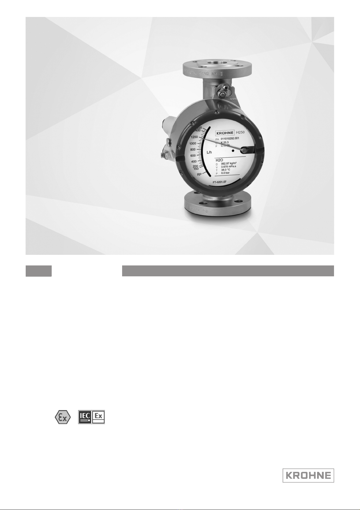
2.1 Device description
Variable area flowmeters measure and display the volume flow of flammable and non-
flammable gases and liquids. Depending on the device version, electrical limit switch contacts
and a 4...20 mA signal output with HART
®
communication, a Foundation Fieldbus interface or a
Profibus PA interface can be installed in the indication unit.
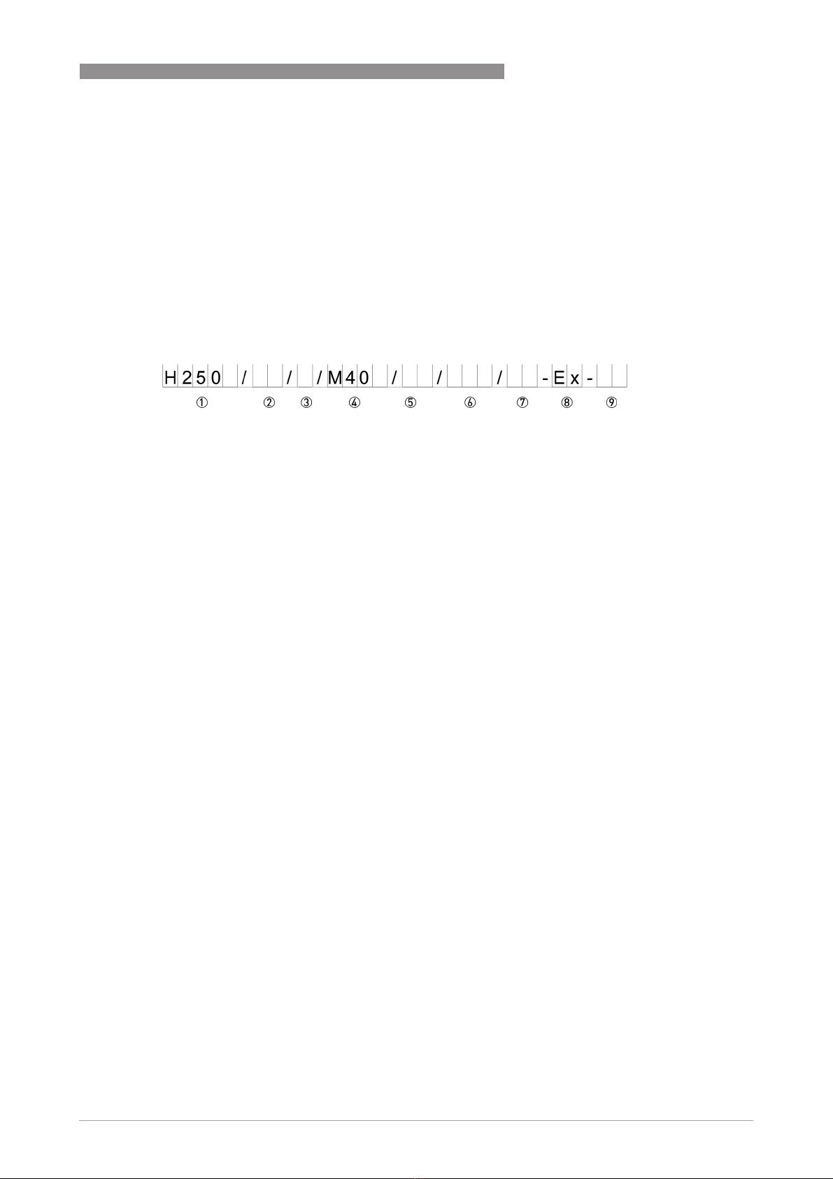
2.2 Description code
The safety description code consists of the following elements *:
* positions which are not needed are omitted (no blank positions)
Figure 2-1: Safety description code
1 Type series of measuring unit H250
Type series of measuring unit H250Type series of measuring unit H250
Type series of measuring unit H250
H250 - standard version, vertical upwards
H250H - horizontal orientation
H250U - vertical downwards
2 Measuring unit materials / versions
Measuring unit materials / versionsMeasuring unit materials / versions
Measuring unit materials / versions
RR - stainless steel
C - PTFE or PTFE/ceramics
HC - Hastelloy C
Ti - Titanium
F - Food
3 Heating jacket version
Heating jacket versionHeating jacket version
Heating jacket version
blank - without heating jacket
B - with heating jacket
4 Signal converter version
Signal converter versionSignal converter version
Signal converter version
M40 - aluminium housing, painted (standard)
M40S - aluminium housing with increased corrosion protection
M40R - stainless steel housing
5 High-temperature version
High-temperature versionHigh-temperature version
High-temperature version
blank - without HT extension
HT - with HT extension
6 Electrical signal output
Electrical signal outputElectrical signal output
Electrical signal output
blank - without transmitter
ESK - electrical signal output 4...20 mA (ESK4)
. . . - optionally available with counter, I/O module and display (ESK4-T) or
. . . - Foundation Fieldbus (ESK4-FF) or
. . . - Profibus PA (ESK4-PA)
7 Limit switch
Limit switchLimit switch
Limit switch
blank - without limit switches
K1 - one limit switch
K2 - two limit switches
R1 - 1 Reed switch
R2 - 2 Reed switches
8 Version
VersionVersion
Version
Ex - explosion-protected version
9 SIL version
SIL versionSIL version
SIL version
SE - SIL compliant electronic signal output
SK - SIL compliant limit switch