manuals.online logo
Brands
  1. Home
  2. •
  3. Brands
  4. •
  5. KROHNE
  6. •
  7. Measuring Instrument
  8. •
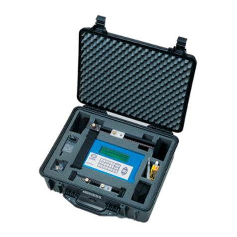
  9. KROHNE OPTISONIC 6300 User manual

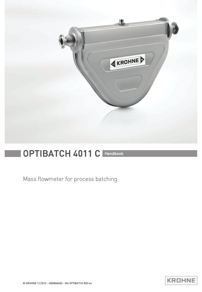
KROHNE OPTISONIC 6300 User manual

For initial set up, we strongly recommend the use of the relevant manuals in addition!
System Configuration
2
1100...230VAC (-15% / +10%), 22VA
Diameter range and rail versions
24VDC (-55% / +30%), 12W
Small
DN15...100 / 0.5...4" DN200...1250 / 8...50"
Small Large
Medium
DN50...400 / 2...16" DN200...4000 / 8...160"
1
Sensor cable connections
2
I/O connections
3
Mains supply connection
10/2020 - 4007758002 - OPTISONIC 6300 R02 en 1
Quick Start
Check the device nameplate to ensure that the device is
delivered according to your order.
www.krohne.com/Downloads
General Device nameplate
Power supply - grounding
Observe without fail the local occupational health and safety regulations.
Any work done on the electrical components of the measuring device may only be carried out by properly
trained specialists.
All work on the electrical connections may only be carried out with the power disconnected.
Take note of the voltage data on the nameplate! Observe the national regulations for electrical installations!
2
Medium The device must be grounded in accordance with
regulations in order to protect personnel against
electric shocks.
For devices used in hazardous areas, additional
safety notes apply; please refer to the Ex
documentation.
Electrical connections signal converter
2 3
3
1
Preferred measuring modes
OPTISONIC 6300
1 Electrical connection
3
Ultrasonic clamp-on flowmeter
Installation, assembly, start-up and maintenance may only be performed by appropriately trained
personnel.
For use in hazardous areas, special codes and regulations are applicable which are supplied in a
separate document that describes all hazardous area relevant information.
The responsibility as to the suitability, intended use and corrosion resistance of the used materials
against the measured fluid of this device rests solely with the operator.
For complete documentation (manuals, supplementary manuals, data sheets and certificates) please
refer to:
Refer to the manual for connection of Ex (/i ) acc. to
NAMUR
24VAC/DC (AC: -15% / +10%; DC: -25% / +30%),
22VA or 12W
120 °
1
2
3
1 -2
3
-
4
5
4
10/2020 - 4007758002 - OPTISONIC 6300 R02 en 2
Follow up with menu X7.2.4…X7.2.8
Run the optimization loop
Repeat if necessary. Adjust settings
in menu
X5 / X7 and finish with
X7.2.9…7.2.11
Read the advised mounting distance in
menu X7.2.3
Enter the values for the installation menu,
X1...X7.2.8
* Change the position of the transducer
Greasing the transducer surfaces
≥ 10 × ∅ ≥ 5 × ∅
General installation of the rails
For more information refer to the manual.
Pump, control valve - open feed / discharge
≥ 20 × ∅
Installation position
Choose the applicable measuring mode
Choose sensor size
Go through menu X1...X5
Check the OPTISONIC 6300 manual for more details
on installation options (e.g. Large version installation)
General configuration instructions
Go through menu X1...X5
The advised distance (menu X7.2.3)
2 Installation
∠α
20 °
Measuring mode
1
Press > 2.5 s ↑ ↓ ↑ ↓ ↑ ↓ > 2
4Signal strength
5Operating keys
Measurin
g
mode
Press > 2.5 s ↑ ↓ ↑ ↓
X6 if pipe=2 at X4.1
1
↑ ↓ ↑ ↓ ↑ ↓ ↑ ↓ ↑ ↓ ↑ ↓ ↑ ↓
1shows when configuring a 2 pipe installation
10/2020 - 4007758002 - OPTISONIC 6300 R02 en 3
X7.1 transducer set
4 Quick Setup
A4.2 unit
X4.2 number of paths
X5 pipe data
X5.2 diameter
X4 pipe configuration
X5.3 pipe material
select
X4.1 number of pipes
X7
install transd. 1
X Installation
Select menu Functions
↑ ↓
Select menu select Submenu
X3.3 free unit
X5.8 liner thickness
X6._: identical to X5._
X3.5 velocity
X1 language
X2 GDC IR interface
X3 units
3 Installation Menu X
X9
transducer sets
A4.3 range
A4.4 low fow cutoff
X9.3 Tb serial no.
X9.4 Tb calibration no.
Ready? or next transducer? /
install transd. 2 /
X8._ is identical to X7._
A5.1 measurement
A5.1 value p. pulse
A5.2 pulse value unit
A5.1 low fow cutoff
X9.1 Ta serial no.
X9.2 Ta calibration no.
X5.14 pipe temperature
A4.5 time constant
Functions
X3.1 size
3Measured variable
↑ ↓ >
select Submenu
X3.6 density
X3.7 temperature
X7.2.1 calibration number
X9.5 Tc serial no.
A1 Language
A
Quick Setup A2 Tag
A3 Reset
A4
Analog Outputs
A5
Digital Outputs
A6 GDC IR interface
A3.1 reset errors
A3.2 totalizer 1
A3.3 totalizer 2
A3.4 totalizer 3
A4.1 measurement
X3.2 volume flow
X9.6 Tc calibration no.
Tag number
Status message
X5.9 fluid
X5.10 VoS fluid
X5.11 density
X5.12 glycol % vol.
X5.13 dynamic viscosity
X5.4 VoS pipe material
X5.5 wall thickness
X5.6 liner material
X5.7 velocity of sound
X3.4 [m3/s]*factor
X7.2.11 end installation
X7.2.9 path ready?
X7.2.2 number of traverses
X7.2.3 mount transducers at
X7.2.4 act. flow, prelim.
X7.2.5 check signal
X7.2.6 actual distance
X7.2.7 optimize distance
X7.2.8 act.flow, prelim.
↵>
↵
>
↵↵
>
↵
>
↵
>
↵
>
↵
>
↵
>
↵
>
↵
Current out
p
ut active Ia
(
basic I/O
)
Pulse/fre
q
uenc
y
out
p
ut
p
assive P
p
(
modular I/O
)
C
urren
t
ou
t
pu
t
pass
i
ve
I
p
(b
as
i
c
I/O)
Pulse/ fre
q
uenc
y
out
p
ut
p
assive PN, NAMUR
(
modular I/O
)
Pulse/fre
q
uenc
y
out
p
ut
p
assive P
p
(
basic I/O
)
Status out
p
ut/limit switch active Sa,
(
modular I/O
)
Status output/limit switch passive Sp (basic I/O) Status out
p
ut/limit switch
p
assive S
p
,
(
modular I/O
)
Current output active Ia (modular/Ex i I/O) Control input active Ca, (modular I/O)
Current output passive Ip (modular/Ex i I/O) Control input passive Cp, (modular/Ex i I/O)
www.krohne.com
Pulse/fre
q
uenc
y
out
p
ut active Pa
(
modular I/O
)
Control input active CN to NAMUR, (modular I/O)
10/2020 - 4007758002 - OPTISONIC 6300 R02 en 4
Then “Select your country“ from the drop-down
list at the top left of the page
Observe connection polarity
Connection diagram
Control input passive Cp (basic I/O)
Contact
To view all KROHNE locations and contact details visit:
Status output/limit switch SN, NAMUR, (modular I/O)

Other manuals for OPTISONIC 6300

8

Other KROHNE Measuring Instrument manuals

KROHNE OPTISONIC 6300 User manual

KROHNE

KROHNE OPTISONIC 6300 User manual

KROHNE OPTISONIC 1400 User manual

KROHNE

KROHNE OPTISONIC 1400 User manual

KROHNE Optisonic 6300 P User manual

KROHNE

KROHNE Optisonic 6300 P User manual

KROHNE DK32 Series Wiring diagram

KROHNE

KROHNE DK32 Series Wiring diagram

KROHNE ALTOSONIC 5 User manual

KROHNE

KROHNE ALTOSONIC 5 User manual

KROHNE H250 M9 Wiring diagram

KROHNE

KROHNE H250 M9 Wiring diagram

KROHNE GA24 Wiring diagram

KROHNE

KROHNE GA24 Wiring diagram

KROHNE CORIMASS MFM 4085 K/F User manual

KROHNE

KROHNE CORIMASS MFM 4085 K/F User manual

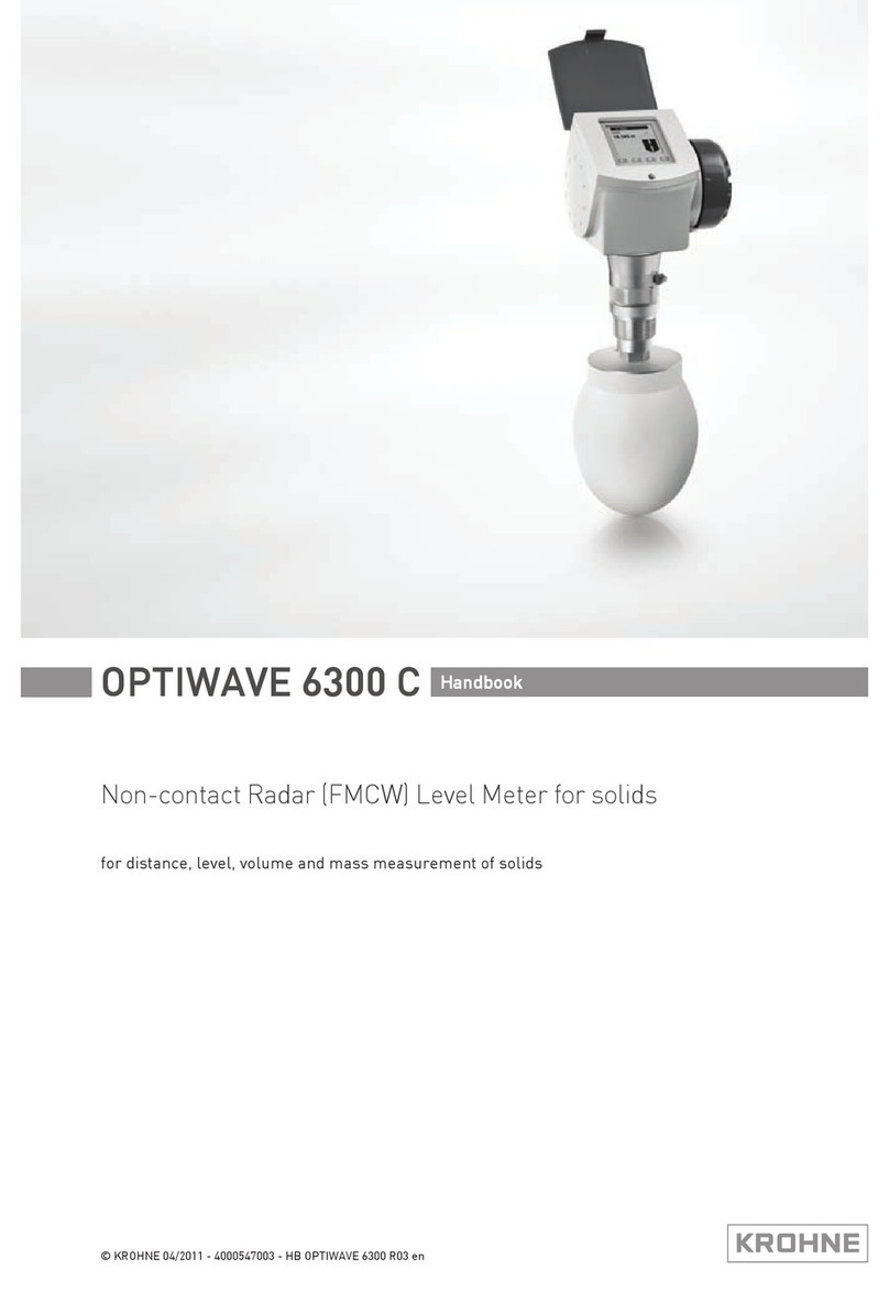
KROHNE OPTIWAVE 6300 C User manual

KROHNE

KROHNE OPTIWAVE 6300 C User manual

KROHNE OPTISWIRL 2100 User manual

KROHNE

KROHNE OPTISWIRL 2100 User manual

KROHNE OPTIMASS 7400 User manual

KROHNE

KROHNE OPTIMASS 7400 User manual

KROHNE OPTIFLUX 2070 User manual

KROHNE

KROHNE OPTIFLUX 2070 User manual

KROHNE DK37/M8 Wiring diagram

KROHNE

KROHNE DK37/M8 Wiring diagram

KROHNE OPTIFLUX 5000 User manual

KROHNE

KROHNE OPTIFLUX 5000 User manual

KROHNE OPTISONIC 6300 F Ex Series User manual

KROHNE

KROHNE OPTISONIC 6300 F Ex Series User manual

KROHNE OPTIWAVE 7300 C User manual

KROHNE

KROHNE OPTIWAVE 7300 C User manual

KROHNE UFM 3030 User manual

KROHNE

KROHNE UFM 3030 User manual

KROHNE OPTIFLUX 400 Series Wiring diagram

KROHNE

KROHNE OPTIFLUX 400 Series Wiring diagram

KROHNE IFC100 User manual

KROHNE

KROHNE IFC100 User manual

KROHNE OPTISONIC 7300 Wiring diagram

KROHNE

KROHNE OPTISONIC 7300 Wiring diagram

KROHNE OPTIWAVE 7300 C User manual

KROHNE

KROHNE OPTIWAVE 7300 C User manual

KROHNE OPTISWIRL 4200 User manual

KROHNE

KROHNE OPTISWIRL 4200 User manual

KROHNE OPTICHECK User manual

KROHNE

KROHNE OPTICHECK User manual

KROHNE SMARTPAT COND 5200 Wiring diagram

KROHNE

KROHNE SMARTPAT COND 5200 Wiring diagram

Popular Measuring Instrument manuals by other brands

McCrometer Mc Propeller Retrofit instruction

McCrometer

McCrometer Mc Propeller Retrofit instruction

TempAlert Bluetooth Smart Probe user manual

TempAlert

TempAlert Bluetooth Smart Probe user manual

TRAMEX CME 4 user guide

TRAMEX

TRAMEX CME 4 user guide

Peak Atlas LCR45 user guide

Peak

Peak Atlas LCR45 user guide

Winland EnviroAlert EA200 quick start guide

Winland

Winland EnviroAlert EA200 quick start guide

Logitek TRU-VU Operation & service manual

Logitek

Logitek TRU-VU Operation & service manual

TESTO 830-T4 instruction manual

TESTO

TESTO 830-T4 instruction manual

Loadsensing LS-G6-LASTIL90 user guide

Loadsensing

Loadsensing LS-G6-LASTIL90 user guide

Tecsis F7301 operating manual

Tecsis

Tecsis F7301 operating manual

Emerson Rosemount CT5100 quick start guide

Emerson

Emerson Rosemount CT5100 quick start guide

Meggitt VibroSmart VSA301 Hardware manual

Meggitt

Meggitt VibroSmart VSA301 Hardware manual

LCM SYSTEMS TR150 instruction manual

LCM SYSTEMS

LCM SYSTEMS TR150 instruction manual

Keeler D-KAT R Instructions for use

Keeler

Keeler D-KAT R Instructions for use

Pentax TH-E10 instruction manual

Pentax

Pentax TH-E10 instruction manual

Renishaw LP2 Installation and user guide

Renishaw

Renishaw LP2 Installation and user guide

NEO PQA8000 user manual

NEO

NEO PQA8000 user manual

ABB Relion 670 series Applications manual

ABB

ABB Relion 670 series Applications manual

CST/BERGER LASERMARK GIZLT-3 Original instructions

CST/BERGER

CST/BERGER LASERMARK GIZLT-3 Original instructions

manuals.online logo
manuals.online logoBrands
  • About & Mission
  • Contact us
  • Privacy Policy
  • Terms and Conditions

Copyright 2025 Manuals.Online. All Rights Reserved.