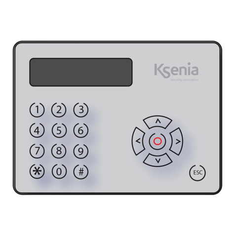
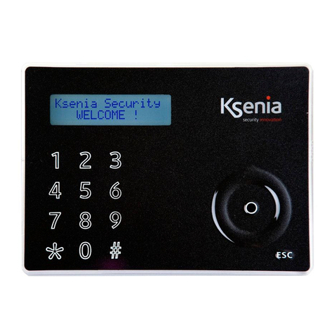
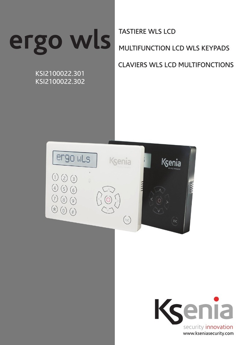
Ksenia ergo wls KSI2100022.301 User manual

KSI2100022.301
KSI2100022.302

2
INTRODUCTION
The new Keypads of ergo wls series with Wide Dot Matrix LCD Display have been added to the controls, and
programming and managing user interfaces for Ksenia lares Control Panels.
TECHNICAL DATA
Warning: Use only the original Ksenia Security batteries. In order to avoid damage to the device and to Keep the
safe device operation guaranteed, it’s recommended to replace the battery within one month from the faulty
battery signal.
Warning! A battery may explode if incorrectly handled: do not recharge, open or burn it.
*“Fast Addressing System”: pas besoin de prérégler l’adresse de l’appareil
(détection automatique par la centrale lares / communicateur)
MAIN FEATURES ergo wls
Wide Dot matrix LCD display (viewing area 79 x 19 mm)
Integrated Microphone and Speaker
“Fast Addressing System” *
Remote listening function
Master programming for gemino and duo UNIVERSAL
Power (only wls mode) Battery KSI7203019.000 non rechargeable Lithium
battery pack
Power (wls and bus mode) 3V / 1900 mA/h
Power (wls mode and row of docking station) Battery
KSI7203709.000
rechargeable Lithium battery
pack 3,7V 900mAh
Consumption 15mA standby,
200mA max
Operating temperature range 5° - 40° C
Overall Dimension 163 X 119 X 14,5 mm
Weight 240 g
Protection degree IP 34
White version KSI2100022.301
Black version KSI2100022.302

3
Cable gland
FIGURE 1 - FRONT VIEW OF THE KEYPAD BASE
FIGURE 2 - PARTS DESCRIPTION AND PCBA TERMINALS
C010
k18121PP
8Ω
4
6
2
3
5
7
1
Note: DO NOT REMOVE PCB AND DISPLAY FROM PLASTIC SUPPORT
USB connector
+ A B - : Connection clamps on KSI-BUS
Anti opening / tamper switch (Tamper)
Loudspeakers contact
Snap fingers
Battery Connector
Battery Pack
A
B
4
4 1
6
5
2
3
7
DISPLAY
USB connector
PARTS DESCRIPTION
Easy open hole to be opened to Built-In installation on DIN 530 box
Eyelets for 60mm-screws-distance boxes
Place a wall mount screw to enable anti opening and removal tamper
Speaker

4
To open the keypad, please proceed as follows:
Push snap fingers ( A ) using a screw driver Pull outward
Audio mic hole
FIGURE 3 - FRONT
Display
FIGURE 4 - OPENING
123
456
789
*#0
ESC
4.4
4.2
4.3
4.1
5
1
2
4
3
6
7
USB Connector
Scroll, also including:
4.1. Left arrow
4.2. Down arrow
4.3. Right arrow
4.4. Up arrow
ENTER key
ESC key
Alphanumeric keypad with 1 a 9, * and # keys

5
SELECT OPERATING MODE 1 (NON-RECHARGEABLE WIRELESS KEYPAD)
1. Turn on the acquisition mode from the control panel.
2. Press and hold the ESC key on your keypad until you see on the display the message “Enroll Posted!”
3. If the acquisition is successful, on the keypad is displayed the message “Enroll Done!”
4. Refer to the manual of the control panel for details.
Inserting and connecting a non-rechargeable battery type KSI7203019.000, ergo wls keypad ONLY works in mode
1 (wireless keyboard with non-rechargeable battery).
Note: the device notify the exit time and pre-alarm entry time, if the “AUDIO ALERT IN/OUT” function is
enabled in the system.
OPERATION MODES
ergo wls can be set to operate in six different ways:
Mode 1 - Wireless keypad with non-rechargeable battery
Mode 2 - Wireless keypad with rechargeable battery
Mode 3 - Wired keypad (technical features as ergo M) on the docking station,
or wireless if removed (with rechargeable battery)
Mode 4 - Wired keypad (technical features as ergo M) but with wireless receiver (without battery)
Mode 5 - Wired keypad (technical features as ergo M) but with wireless repeater (without battery)
Mode 6 - Wired keypad (technical features as ergo M) (without battery)
ACQUISITION
When not in use the keypad is put in the state of energy saving and leaves off both the display and the back-light.
Pressing any button on the device turns on and the display shows the system status. At this point you can enter
the user PIN to perform disarming / arming actions or to access the user menu. If the number key is held down
for more than 1 second, the keypad goes directly from the state of energy saving to the PIN input without going
through the status display. Instead, with a pressure of about 3 seconds of the number keys 1 to 6, it is available
the execution of a scenario. After performing the desired action, the keypad returns to the energy saving state by
pressing the ESC key and after 10 seconds of inactivity. During the use, if the keypad for any reason failed to send
the command to the control panel, the display shows the “KO Communication” message.
OPERATING MODE 1 (NON-RECHARGEABLE WIRELESS KEYPAD)

6
USER MENU
For system management there is also a short user menu. To enter the User menu simply enter one of the
programmed user codes (default 000001) and press
ENTER.
The options on this menu are:
• Reset Alarms: allows you to stop any alarms in progress, and delete any
memories.
• Reset Phone: allows you to stop any Contact ID actions.
ACTIVATION OF ARMING/DISARMING MODE
To activate one of the four possible arming mode follow the steps below:
• Enter, while the keypad is in rest condition, one of the programmed user code (default 000001)
• Press the button (1) Arming,
• Press the button (2) Partial arming 1,
• Press the button (3) Partial arming 2
• Press the button (0) Disarming.
• If the system is ready to arm displays a success message.
If, however, there are the causes that prevent the arming (for example violated sensors)
the display shows the system not ready message.
Pressing the ENTER button displays the causes that prevent the arming
• If the cause that prevents the arming is that one or more sensors are violated, this can still be forced excluding
them one by one. To do this, simply press the ENTER button when viewing the sensors that prevent the arming.
Once excluding all sensors violated, even by pressing the ENTER key, the arming is forced. The sensors excluded
at this stage will be re-included automatically when the system is disarmed.
VIEWING THE STATE OF THE SYSTEM
MAINTENANCE It is in progress a maintenance by the installer. In this state, the control panel does
not process alarms or sabotage.
TAMPER It is an ongoing tamper
ALARM! It is an ongoing alarm
TAMPER MEMORY This is a tamper alarm memory in the system
ALARM MEMORY there is an alarm memory
FAULTS IN PROGRESS there is at least one fault
TIME ENTRY It is in progress the entry time
TIME OUT It is in progress the exit time
EXCLUDED SENSORS there is at least one manually excluded sensor
SYSTEM OK there are no anomalies
The second line of the display shows the following information:
• Date and time
• Arming/Disarming state of the system
• System ready or not ready to arm
• Outdoor temperature (if in the system there is also a Ksenia siren imago WLS)
As stated above, the system status display can be enabled on the keypad display by briefly pressing any key.
On the first line, in order of priority, the information displayed is:

7
SELECTION OF OPERATING MODE FROM 2 TO 6
The mode of operation from 2 to 6 are selected via a menu.
To enter the menu you need to power the keypad ergo wls with a rechargeable battery or via BUS,
leaving the Switch Snatch (Tamper) opened. Fig. 2 (PART DESCRIPTION).
ergo wls allows different choices depending on the type of power supply detected:
If powered with rechargeable battery possible modes are:
• Mode 1 - Remote control with rechargeable battery (the display shows “no docking bus”)
• Mode 2 - keypad on docking station and remote control if removed (display shows “docking)
If powered by BUS possible modes are:
• Mode 1 - Wireless keypad with rechargeable battery (the display shows “no docking bus”)
• Mode 2 - keypad on docking station and remote control if removed (display shows “docking)
• Mode 3 - Keypad + Wireless transceiver (display shows “ergo + duo”)
• Mode 4 - Keypad + Wireless repeater (display shows “ergo + duo repeat.”)
• Mode 5 - Only wired keypad (the display shows “ergo M only”)
Using the keys arrow up and arrow down (fig. 4) you can scroll through the various menu items.
Press ENTER to select the desired operating mode.
Warning: Use only original batteries Ksenia KSI7203019.000 To avoid damage to the device and continue to
ensure the operation of the same, it is recommended to replace the battery within one month of reporting faulty
battery.
Warning! A battery can explode if treated incorrectly: not recharge, disassemble or dispose on re.
BATTERY LEVEL
The keypad continuously checks the level of battery power and displays it on the display using the symbology
described below:
Charge battery Low battery
Level 4 Level 3 Level 2 Level 1 Level 0
BATTERY REPLACEMENT
1 Open the front panel of the keypad, as described in Fig. 4 (PART DESCRIPTION) (OPEN)
2 Disconnect the old battery pack (6), Fig. 2 (PART DESCRIPTION)
3 Connect the new battery pack to the connector (5)
4 Close the front cover by snapping the locking hooks (4)
1. Turn on the acquisition mode from the control panel
2. Press and hold the ESC key on your keypad until you see on the display the message “Enroll Posted!”
3. If the acquisition is successful on the keypad it is displayed display the message “Enroll Done!”
4. Refer to the manual of the control panel for details.
ACQUISITION

8
MODES OF OPERATION (4) WIRED KEYPAD WITH WIRELESS TRANSCEIVER
In mode 4 - wired keypad + transceiver Wireless (display shows “ergo + duo”),
In this configuration there is no battery to be used and the BUS cable MUST be wired directly to the terminal 1
fig. 2 (DESCRIPTION OF THE PARTS PCB).
Being wired BUS cable (A + B -) the keypad has all the ERGO M keypad functionalities, its functions are described
in section (Mode 6 “Wired Keypad”).
The device thus configured also implements the functionality “duo”, which is a bi-directional wireless
transceiver that receives information from various installed wireless devices and transmits them to the lares
control panel. In this configuration the ergo wls works on BUS as two devices: aergo M and a duo BUS.
The two devices have the same serial number.
MODES OF OPERATION (5) WIRED KEYPAD WITH WIRELESS REPEATER
In mode 5 - Wired Keypad + Wireless repeater (display shows “ergo + repeat duo.”)
In this configuration there is no battery to be used and the BUS cable MUST be wired directly to the terminal 1
fig. 2 (DESCRIPTION OF THE PARTS PCB).
Being wired BUS cable (A + B -) the keypad has all the ergo M keypad functionalities its functions are described
in section (Mode 6 “Wired Keypad”).
The device in this configured also implements the functionality “duo Repeater”, a bi-directional wireless
transceiver that receives information from various installed wireless devices and transmits them to a duo BUS.
In this configuration the ergo wls works on BUS as one device, ie a ergo M; also it works as a duo wireless.
The two devices have the same serial number.
MODES OF OPERATION (3) WIRED KEYPAD ON DOCKING STATION / WIRELESS KEYPAD IF REMOVED
In mode 3 - wired keypad on the docking station and wireless keypad mode if removed “docking”.
The keypad if anchored to its charging station (docking station) where wired BUS cable (A + B -) has all the
functionalities of the keypad ERGO M its functions are described in section (Mode 6 “Wired Keypad”).
If removed from its charging station acts as the mode 2 (wireless keypad), the battery charging functions remain
active through docking station and USB cable connecting a standard battery charger for Smartphone to the USB
connector 7 (Figure 2 and Figure 3).
It is possible to use only batteries Ksenia KSI7203709.000 model.
Dispose of used batteries according to the instructions.
Warning! The battery can explode if treated incorrectly. Do not open or throw on re
The battery is recharged by connecting a standard USB charging batteries for Smartphone from 5VDC
to the keypad, or by placing the keypad in the Docking Station.
OPERATING MODE (2) WIRELESS KEYPAD WITH RECHARGEABLE BATTERY
In mode 2 - Wireless keypad with rechargeable battery “docking bus no.”
The keypad behaves as in mode 6 (remote control), however, are active the battery charging functions via
Docking Station and / or USB cable
connecting a standard battery charger for Smartphone to the USB connector 7 (Figure 2 and Figure 3).
It is possible to use only batteries Ksenia KSI7203709.000 model.
Dispose used batteries according to the instructions.
9
FUNCTIONS
INSTALLATION
INSTALLATION ON A SWITCH BOX OR ON WALL - MOUNTED
INSTALLATION NOTES
• Display of system status
• Display of functioning parameters ( date/time, active GSM network, GSM level, etc)
• System commands (complete or partial arming, reset, activation of outputs terminals, phone calls, etc.)
• Full Programming of system parameters
• Programming of local parameters (audio volume, backlight levels and LCD contrast)
• Vocal messages recording
Ksenia ergo wls can be installed on any plain surface. Furthermore, in the back ithen are 3 easy-open holes,
suitable for DIN503 and for 60mm-screw-distance boxes.
1. Push the cable through to the opening. ( fig. 1-7 )
2. Fix the keypad base to the wall - box with the supplied screws through the eyelets. ( fig.1-1,3 )
To wall mount the keypad, use proper plugs and screws (not supplied) through the eyelets.
( fig.1, 1-3 o 1-2 )
3. Use a plug and the apposite screw to enable tamper functionality (fig. 1-4 )
4. Connect the cables to the terminals on the rear of the keypad.
5. Close the keypad properly. (fig. 2-5)
1. At every new installation when ergo wls is switched on ( but not wire to bus ), the display
will show the following information:
• First line: “Ksenia Security”
• Second Line: from the rst character from the left the FW version loaded on the device (x.xx.xxx),
as from the 10° character the device serial-number (six numeric characters).
And at the 16th character S or M depends on the model
MODES OF OPERATION (6) WIRED KEYPAD WITHOUT BATTERY
In mode 6 - wired keypad mode (display shows “ergo M only”),
In this configuration there is no battery to be used and the BUS cable MUST be wired directly to the terminal 1
fig. 2 (DESCRIPTION OF THE PARTS PCB).
Being wired BUS cable (A + B -) the keypad has all the ergo M keypad functionalities,
Warning! while using the keypad in mode 6 (ergo M only), all wireless functions are disabled.

10
DISPLAY
The display shows all the information and the data ergo wls can manage. The display can show up to 2 lines ,16
characters each, but ergo has an automatic scroll system to show 32 characters rows.
CONTRAST ADJUSTMENT
Acting on keys “Left” or “Right” when keypad is idle, a sliding bar used for contrast adjustment will be enabled.
The ENTER key will store the new contrast value, the ESC key will leave value unchanged.
Values will change on a 3 seconds key holding.
KEYPAD
KEYPAD FUNCTION DESCRIPTION
It is conceived for data-entering (data/character) during the configuration process, PIN entering (programmer or
user) etc. By touching or exerting a slight pressure on the area corresponding to the desired number, it allows to
enter alphanumeric characters (letters and symbols) in addition to 0-9 numbers , depending on the
operating context (menu). This is possible because the keypad is provided with the c mobile phone mode
technology, which allows to change the entered character depending on the settings (refer to the following key-
characters match chart).
Two ways to move forward the display line are possible while entering a text: using
another key or avoiding touching any key for 3 seconds after the last type.
Key-characters match chart:
KEY FONT:
0 ( ) / % - _ # *
1 “ “ ‘space’ ? ! , . \ ‘ &
A B C a b c 2 $ @
D E F d e f 3 ; <
G H I g h i 4 = >
J K L j k l 5 [ ]
M N O m n o 6 { :
P Q R S p q r s 7
T U V t u v 8 + }
W X Y Z w x y z 9

11
ESC KEY
The ESC key allows to exit the current menu, and go back to the previous level. This means that, whether in a
branched menu, repeated clics on the key will be needed to get back, for example to main menu.
A 2 S. pressure on the ‘ESC’ key when the keyboard is not used allows the activation of the cleaning function. As
the name suggests, this function disable the keypad functionality for front-cleaning purposes.
During the keypad block due to the activation of the cleaning function, the following information will be
displayed on the “ergo” screen:
• First line: “Keypad block”
• Second line: the time for the cleaning will be marked by an increasing dot line, moving from left to right.
When the line will be filled up the ergo S (ergo M) will be ready to accept commands again.
ENTER KEY
The Enter key allows to enter the intended menu when browsing, to start editing during configuration phase or to
confirm the input of a data during an editing session.
In this regard, the following conduct:
• When browsing the main menu, a pressure on the Enter key allows to enter the sub-menu and to
keep exploring in case the menu has several branches
• When visualizing the conguration data, a push on the Enter key permits the editing of the data
itself and this involves:
- the configured object flashes if it is selectable with a predefined set through the Scroll;
- the first character of a string flashes in case the string its being edited;
- the first number flashes when a numeric data or a phone number is being edited.
• During the editing phase, a further pressure on the ENTER key conrms the immission or modication
of the data (which will be sent to gemino or lares that will store it) and the ergo wls display
permits to show: the following data, the subsequent menu or the data itself.
If “Enter” key is pushed when ergo is in standby mode, the display will show the installator’s data (Name,
Number or email address) if they were set during the keypad configuration. In case the installator’s data were not
available, the screen will display the two following default line:
<Installator>
<Information>
Note: to clean the device it is recommended to use a damp cloth and avoid alcohol and solvents.

12
Slide forwards or backwards the menu entries:
• Pick the conguration data to enter (which will only be the suitable ones for the changing data)
such as: character, numbers, presetted values, etc.
This area also allows to use the following functions:
• “Up arrow”. If a prolonged pressure (about 0,5 s.) is exerted on the 4.4 area of the gure 5; the
same functions described for the clockwise moved scroll are activated (obviously the slide of the
menu or the configuration
data available during this procedure is slower since it works at 0,5 seconds steps);
• “Down arrow”. If a prolonged pressure (about 0,5 s.) is exerted on the 4.2 area of the gure 5;
the same functions described for the anticlockwise moved scroll are activated (obviously the
slide of the menu or the configuration data available during this procedure is slower since it works
at 0,5 seconds steps);
• ”Left arrow”. A prolonged pressure (about 0,5 s.) exerted on the 4.1 area of the gure 5 allows to
slide backwards along a line; if settled on the last character / number to the right, this function
allows to cancel in order one or more data characters / numbers until they are completely
deleted;
• ”Right arrow”. A prolonged pressure (about 0,5 s.) exerted on the 4.3 area of the gure 5 allows
to slide backwards along a line; if it is longer than the 16 characters the ergo display can show.
The forward slide can work in different ways depending on the data we are working on:
if we are browsing a menu it will slide 16 characters at any one time, while during data editing it
will only slide character at any one time.
ARROW KEYS
1095 Budapest, Mester u. 34.
Tel.: *218-5542, 215-9771, 215-7550,
216-7017, 216-7018 Fax: 218-5542
Mobil: 30 940-1970, 30 959-0930
www.delton.hu
1141 Budapest, Fogarasi út 77.
Tel.: *220-7940, 220-7814, 220-7959,
220-8881, 364-3428 Fax: 220-7940
Mobil: 30 531-5454, 30 939-9989
Other manuals for ergo wls KSI2100022.301
1
This manual suits for next models
1
Table of contents
Other Ksenia Keypad manuals

Ksenia
Ksenia ergo-T User manual

Ksenia
Ksenia ergo wls User manual

Ksenia
Ksenia ergo-X KSI2100031.302 Use and care manual

Ksenia
Ksenia ergo-T User manual

Ksenia
Ksenia ergo A KSI2100030.301 WHITE User manual

Ksenia
Ksenia ergo M Assembly instructions

Ksenia
Ksenia ergo M User manual

Ksenia
Ksenia ergo Operating instructions

Ksenia
Ksenia ergo M User manual

Ksenia
Ksenia KSI2100000.300 Operating instructions